![]()
INSTALLATION MANUAL: PDC BELL SERIES
NOTICE TO THE INSTALLER
This manual provides an overview and the installation instructions for the PDC bell series 612, 624, 812, 824, 1012, and 1024. All connections are power limited and should be wired in accordance with the requirements of NFPA 70 (NEC) and NFPA 72 (National Fire Alarm Code). Failure to follow the wiring diagrams in the following pages will cause the bell to not operate as intended.
DESCRIPTION
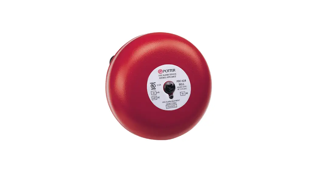
The PDC is a DC bell designed for easy indoor and outdoor installation wherever required. The semi-flush design has an optional waterproof backbox available.
TECHNICAL SPECIFICATIONS
Audibility Rating (dB at 10 ft)
| RATING | 6– GONG SIZE | 8– GONG SIZE | 10– GONG SIZE | |||
| VOLTAGE | RATED CURRENT | SOUND LEVEL AT 10 FT dB | RATED CURRENT | SOUND LEVEL AT 10 FT dB | RATED CURRENT | SOUND LEVEL AT 10 FT dB |
| 12VDC | 200mA | 96 | 200mA | 96 | 200mA | 96 |
| 24VDC | 20mA | 95 | 20mA | 83 | 20mA | 85 |
INSTALLATION
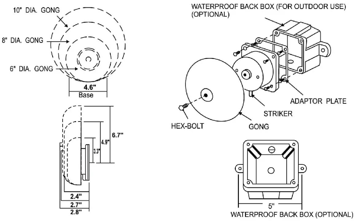
- Remove the gong.
- Wire the bell in the circuit.
- Mount bell mechanism on 4″ square outlet box with the striker facing down.
- Replace the gong.
- Mount the bell a minimum of 8ft. above the floor or as close to the ceiling as possible
- Observe the polarity when installing the bell. Polarized bells provide Red (+) and Black (-) lead wires.
WIRING AND SIZING
The PDC is connected to the master panel using a The connections are power limited and supervised. The wiring diagram shown below illustrates how to connect a PDC bell.
FIGURE 1. EXAMPLE OF WIRING A PDC BELL
D. C. BELLS (OBSERVE POLARITY)
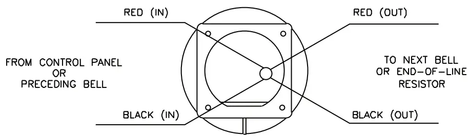
CAUTION: WHEN ELECTRICAL SUPERVISION IS REQUIRED USE IN AND OUT LEADS AS SHOWN
NOTES:
- OBSERVE POLARITY TO RING D.C. BELLS.
- RED WIRES POSITIVE (+).
- BLACK WIRES NEGATIVE (-).
- EOL RESISTOR IS SUPPLIED BY A FIRE ALARM CONTROL PANEL.
FIGURE 2. PDC BELL MOUNTING
NOTES:
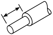
- Wire preparation strip all wires 1/4 inch from their edges as shown here:
– Stripping too much insulation may cause a ground fault.
– Stripping too little may cause a poor connection and subsequently an open circuit.
These instructions do not purport to cover all the details or variations in the equipment described, nor provide for every possible contingency to be met in connection with installation, operation, and maintenance.
Specifications are subject to change without prior notification.
For Technical Assistance contact Potter Electric Signal Company at 866-956-1211.
Actual performance is based on the proper application of the product by a qualified professional. Should further information be desired or should particular problems arise, which are not covered sufficiently for the purchaser’s purpose, the matter should be referred to a distributor in your region?
Potter Electric Signal Company, LLC • St. Louis, MO • Phone: 800-325-3936 • www.pottersignal.com


