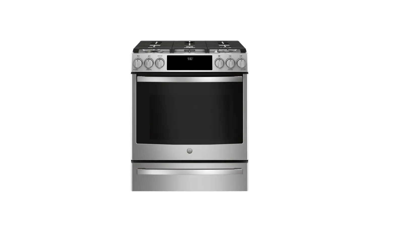
GE APPLIANES PGS930 30-Inch Smart Slide-In Gas Range Instruction Manual
PROPANE CONVERSION INSTRUCTIONS
WARNING Explosion Hazard
![]() WARNING
WARNING
Explosion Hazard
Death or serious injury can result from failure to follow these instructions.
- Service by a qualified service technician only.
- Shut off gas supply and disconnect power before servicing.
- Reconnect all grounding devices after service.
- Replace all parts and panels before operating.
The pressure regulator and the burner orifices are set for natural gas. To use propane gas, the regulator and burner orifices must be converted.
![]() WARNING
WARNING
Do not operate the cooktop or oven burners of this range when using propane (bottled) gas before converting the pressure regulator and burner orifices for propane gas use Failure to do so could cause high flames and toxic fumes which can result in serious injury.
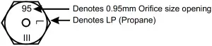
The propane orifices for the cooktop burners are shipped on the back of the range in the location shown.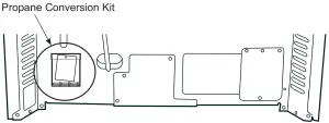
TOOLS REQUIRED
- Adjustable wrench
- Socket wrench with 1/2″ socket and extension
- Phillips head screwdriver
- Flat bladed screwdriver (blade approximately 3/32″ across)
- Nut drivers: 1/4″, 9/32″ or 7mm
To adjust your range for use with propane gas, follow these instructions:
- Disconnect all electrical power, at the main circuit breaker or fuse box.
- Shut off the gas supply to the range by closing the manual shut-off valve.
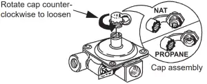
CONVERTING THE PRESSURE REGULATOR
Remove the drawer and panel behind drawer. The pressure regulator is located in the lower, left hand rear corner of the range as viewed from the front.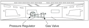
- Use an adjustable wrench to unscrew the hex-nut cap from the pressure regulator.
- Completely remove the protective plastic cap off the threaded metal cap.
Regulator
- Turn the metal cap so the type of gas being converted to is displayed and replace the protective plastic cover.
- Screw the hex-nut cap back into the regulator. (Do not over tighten)
CONVERTING THE COOKTOP BURNERS
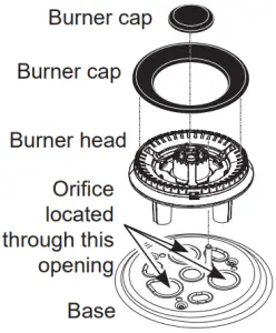
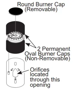
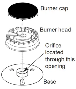
- Remove the top grates, burner caps and burner heads.
Multi-ring
Dual oval burner
Round burner
- Using a 7 mm or 9/32″ nut driver, remove the top burner orifices. These may be accessed through the burner opening in the base.
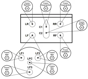
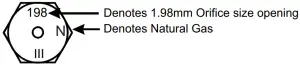
NOTICE: Save these orifices for future conversion back to natural gas. - Remove the propane orifices from the box provided. The propane orifices have the letter “L” on the top. To aid in identifying the proper location for the propane orifices during conversion from Natural Gas to Propane Gas, color codes have been added to the side or top of the orifice. See the chart below. Each orifice may also show a series of engraved marks (I, II, Ill …) located on the top.

BURNER OUTPUT RATINGS: BTU/HR Pro no Gas 10″ W.C.P. BURNER BTU RATE ORIFICE SIZE (in) COLOR Marking LF 18,000 LF1 N/A 0.027 None 69L LF2 N/A 0.027 None 69L LF3 N/A 0.027 None 69L LFC N/A 0.016 None 40L LR 5000 0.026 Red/Yellow 66L RF 15 0.045 Orange/Silver 114L RR 9.5 0.0365 Orange/Light Blue 92L C 8000 C1 9.5 0.0365 Orange/Light Blue 92L C2 6.8 0.03 Blue/Red 76L Broil 13.5 0.042 Grey 042L Bake 16000 0.047 Orange 0.047 - Install the propane orifices in their precise locations.

To prevent leakage, make sure the orifice spuds are securely screwed into the gas supply tubes. - Install the old orifice spuds into the metal box or bracket along with these instructions, and replace onto the back of the range for possible future conversion.
CHECK SURFACE BURNERS
Push and turn a knob to the LITE position. A clicking sound indicates proper operation of the ignition system. When lighting any burner, sparks will appear at all burners but gas flows from only the one selected. Once air is purged from the supply line, burner should light within 4 seconds. After burner lights, rotate the knob out of the LITE position. Try each burner in succession until all burners have been checked.
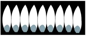
Quality of Flames
Determine the quality of flames visually. Normal burner flames should look like (A) or (B).
- Soft blue flames—Normal for natural gas

- Yellow tips on outer cones—Normal for propane gas
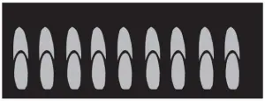
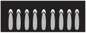
Long, bright yellow flames are not normal. Normal flames may show signs of an orange tint when well heated or signs of flickering orange due to particles in the gas or air.
PROPANE CONVERSION INSTRUCTIONS
31-2000756 Rev. 0 05-20 GEA PGS930
CONVERTING THE OVEN BURNERS
NOTICE: This product cannot be converted to propane by adjusting the oven orifices. The orifices must be replaced for propane.
BAKE BURNER ORIFICE
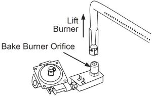
- Remove oven racks, door and oven bottom. Remove the 1/4″ hex screws securing the bake burner.
- The bake burner orifice is on the gas valve located behind the warming drawer. Lift the burner off the orifice and apply a 1/2″ socket on an extension to the hex base of the orifice on the gas valve. Loosen the orifice by turning counter-clockwise and remove.
NOTICE: Save these orifices for future conversion back to natural gas. - Select the propane bake orifice from the kit and install it on the gas valve. lighten until snug.
BROIL BURNER ORIFICE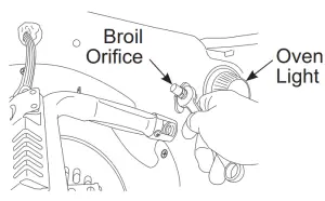
- Remove the 1/4″ hex screw securing the broil burner and allow it to hang down free of the broil orifice.
- Apply a 1/2″ wrench to the hex base of the orifice. Loosen the orifice by turning counter-clockwise and remove.
- Select the propane broil orifice from the kit and install it on the broil elbow. Tighten until snug.
- Replace the broil burner over the orifice and replace the screw securing the burner.
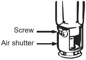
ADJUSTING AIR SHUTTER SETTINGS FOR OVEN BURNERS
The air shutters should be turned to the marked settings NG or propane or set according to the following table.
| BURNER | AIR SHUTTER SETTING FOR PROPANE | AIR SHUTTER SETTING FOR NG |
| Bake | Full open | 0.280′ |
| Broil | 0.690′ | 0.690′ |
- With a Phillips head screwdriver, loosen the screws securing the air shutter on the bake burner. Adjust the air shutter to the dimension given in the above table.
- Turn on the gas.
- Turn on the electricity.
- Reinstall the oven door.
- Turn on the bake burner.

Oven burner flame must be observed with the door closed to properly check flame characteristics. - As you watch the flame with the oven door closed, check the following through the oven door window.
- For Natural Gas, if the flames are yellow, open the air shutter more.
- If the flames blow away or flutter from the burner, close the air shutter slightly.
- Turn bake burner off and repeat with broil burner.
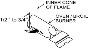
 WARNING
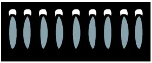
If you attempt to measure the inner cone of the flame, please use caution. burns could result. - Checking the flame size. It should be approximately 1/2″ to 3/4″ long for the bake and broil bumers. The combustion quality of the burner flames needs to be determined visually.

NOTE: If burner flames look like (A), further air shutter adjustment to the bake buner is required. Normal burner flames should look like (B) or (C), depending on the type of gas you use. With propane gas, some yellow tipping on the outer cones is normal.- Yellow flames:
further Adjustment Required
- Yellow tips on outer cones:
Normal for Propane Gas - Soft blue flames:
Normal for Natural Gas
Foreign particles in the gas line may cause an orange flame at first, but this will soon disappear.
- Yellow flames:
- When all adjustments are made and the results are satisfactory:
- Retighten the air shutter screws.
- Replace the oven bottom.
- Replace the storage drawer.
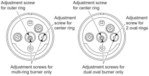
ADJUSTING LOW FLAME SETTING ON COOKTOP BURNERS
Low setting adjustments must be made with other burners in operation on a medium setting. This procedure prevents the low flame from being set too low, resulting in the flame being extinguished when other burners are turned on.
- Turn on all surface burners to medium setting.
- Turn the knob on the burner being adjusted to “LO”.
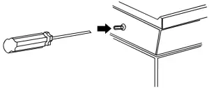
- Remove the knob and insert a small, flat blade screwdriver into the valve shaft and/or side adjustment screw(s) as shown and turn clockwise to fully tighten down the bypass screw(s). Repeat for all valves.
- If flame appears too low or unstable, slowly turn bypass screw counterclockwise until a stable flame exists for each burner. Remember, other burners must be turned on to medium.
SPECIALTY BURNERS
Dual Oval Burner — This burner should be properly adjusted with both bypass screws completely screwed in.
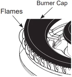
Multi-Ring Burner—The outer ring of flames should be adjusted with the knob at the MED by adjusting the set screw in the center valve shaft. The flames should be adjusted so that they barely curl over the top edge of the burner cap The center ring of flames should be adjusted with the knob at the LO setting by adjusting the set screw to the right of the valve shaft.
- Additionally, for each burner being adjusted, quickly open and close the oven door while observing flame. If flame is extinguished, continue adjusting bypass screw for a larger flame. Repeat door openings until flame is stable.
- Replace the knob.


Center adjustment screw only for all other burners.
SPECIAL NOTE:
To convert the oven back to natural gas, reverse the instructions given in making propane adjustments.
NOTICE: Once the conversion is complete and confirmed, fill out the propane sticker and include your name, organization and date conversion was made. Apply the sticker to the range near the regulator to alert others in the future that this appliance has been converted to propane. If converting back to natural gas from propane, please remove the sticker so others know the appliance is set to use natural gas.
ADDITIONAL INFORMATION
| BURNER OUTPUT RATINGS: BTU/HR | ||||
| NG (Natural) Gas 5” W.C.P. | ||||
| BURNER | BTU RATE | ORIFICE SIZE (in) | COLOR | MARKING |
| LF | 21.000 | |||
| LF1 | N/A | 0.045 | None | 114N |
| LF2 | N/A | 0.045 | None | 114N |
| LF3 | N/A | 0.045 | None | 114N |
| LFC | N/A | 0.025 | None | 63N |
| LR | 5.000 | 0.040 | White/Purple | 101N |
| RF | 15.000 | 0.070 | Brown | 178N |
| RR | 9,500 | 0.0555 | Yellow | 141N |
| C | 8,000 | |||
| C1 | 9,500 | 0.0555 | Yellow | 141N |
| C2 | 6,800 | 0.047 | None | 119N |
| Broil | 16.500 | 0.071 | Black/Blue | 071N |
| Bake | 16.000 | 0.070 | None | 50 |
PROPANE CONVERSION INSTRUCTIONS
31-2000756 Rev. 0 05-20 GEA
PGS930


