![]() High Voltage Differential Probe User Manual
High Voltage Differential Probe User Manual
DP750
Overview
Designed with an unconventional appearance, the DP750 adopts the solution by building in the test line and probe which with shielding function, integrated the interface end in a compact box, no need to twist the cables, leads to a lower noise floor and has less interference.
Max 100MHz bandwidth, Max input voltage 750V, switchable 50X / 500X attenuation ratio, high accuracy, the noise floor is low and is not affected when switching ratio, support one-press Zero calibration, and overvoltage alarm. Support USB power supply, suitable for any brand of oscilloscope. Support direct power supply with Micsig UPI multi-function interface oscilloscope. Automatically matches the scope attenuation coefficient without manual adjustment. The DP750 can be widely used in the research and development, commissioning or maintenance of switching power supplies, frequency converters, electronic ballasts, frequency conversion home appliances, and other electrical power devices.
 Specifications
 Specifications
| Model name | DP750 -100 | DP750 -50 |
| Bandwidth | 100MHz | 50MHz |
| Rise Time | s 3.5ns | s 7ns |
| Attenuation Ratio | SOX; 500X | |
| Gain Accuracy | ±2% | |
| Max Differential Test Voltage (DC+AC PK) | SOX: 7W; 500X: 750V | |
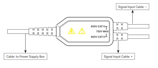
| Max Common-Mode Input Voltage | CAT II 600V | |
| Input Referred Noise | s 12mVrms(50X); s 120mVrms(500X) | |
| Common Mode Rejection Ratio (CMRR) | > 80dB(DC); > 80dB(100KHz); > 60dB(1MHz) | |
| Input Resistance | Differential input impedance: 8M0111.25pF; Each input ground: 4 Mf2112.5pF | |
| Output Voltage | s 1.5V | |
| Power Rate | 1W | |
| Power Supply | Micsig UPI Interface; USB (Adaptor) | |
| Overrange Alarm | Indicator flashes | |
| Dimensions | Power Supply Box: 80*37*22 mm | |
| Signal In/Output Box: 49*25*12.5 mm | ||
| Input Cable Length | 33mm | |
| Output Cable Length | 100mm | |
| Working Temperature | 0°C -40°C | |
| Working Humidity | 10%-85% | |
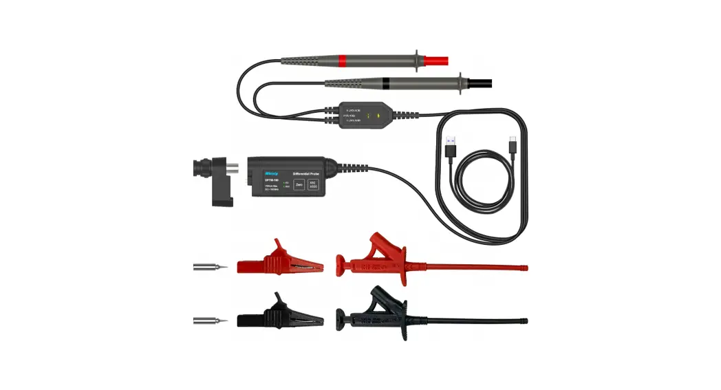
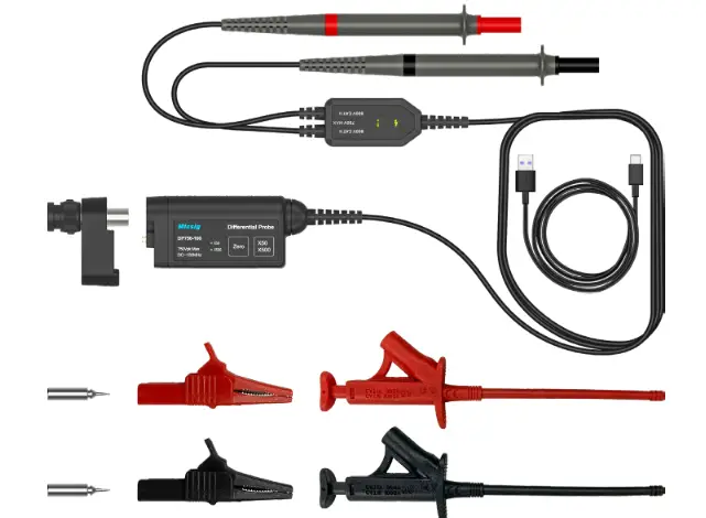
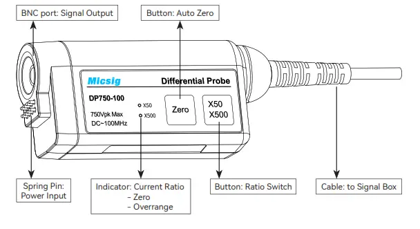
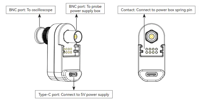
Panel Description
- Differential probe power supply box

- Differential probe signal box

- Power Adapter

Operation Steps
- When the oscilloscope has a Micsig UPI (universal probe interface), connect the differential probe output end to the oscilloscope input channel to power the probe.
- When the oscilloscope does not have a Micsig UPI: Firstly, connect the differential probe to the power adapter PA05, then connect the two to the oscilloscope input channel; Secondly, connect the Type-C cable to the 5V DC power supply to power the adapter.
- Select the appropriate attenuation ratio on the power box of the differential probe, according to the voltage range of the signal under test.
- Connect the signal input line on the signal box of the differential probe to the signal under test to start the measurement. If the signal exceeds the voltage range of the current ratio, the indicator will flash, please turn off the signal under test and disconnect the differential probe power supply.
- Set up the oscilloscope to observe the signal tested by the differential probe.
Precautions
- Before starting the measurement, the zero point of the probe needs to be calibrated: First short-circuit the two input terminals, power on, and press and hold the “Zero” button for 3s, the two indicators will start flashing at the same time, and the Zero point calibration is successful after 3s.
- When the differential probe output is connected to the oscilloscope, the bandwidth of the oscilloscope is required to be no less than 100MHz, and the input impedance of the channel is no less than 1MΩ.
- It is recommended to use it after warming up for 10 minutes to get more accurate data.
- If there is a functional failure of the product, please contact the local dealer or Missing directly.
Warranty
- The main body of this differential probe is guaranteed for 1 year. During the product warranty period, under normal use, the company will be responsible for free maintenance without dismantling and repairing the fault caused by the quality of the product itself.
- The warranty is invalid in the following cases, but maintenance services are provided, labor costs are waived, and only spare parts are charged:
a. Consumers damage any accessories due to improper use, maintenance, and storage.
b. Damage caused by force majeure factors, such as natural disasters, etc. - In the following cases, the company will refuse to provide maintenance services or provide maintenance services for a fee:
a. Unable to provide product packaging or anti-counterfeiting labels on product packaging.
b. The content of the anti-counterfeiting label has been altered or is blurred and unrecognizable.
c. It has been dismantled by any person not authorized by Micsig (eg: changing wires, dismantling internal components, etc.).
d. No sales voucher or the content of the sales voucher does not match the product.
Safety
- Non-professionals should not open the product shell
- Do not use with the product shell open
- When measuring, do not touch any bare metal
- When overload occurs, please disconnect the power supply and input immediately
- Do not use in flammable and explosive environments
![]() Shenzhen Micsig Technology Co., Ltd.
Shenzhen Micsig Technology Co., Ltd.
Phone: +86 755-88600880
Email: [email protected] Web: www.micsig.com
Add: 1F, Huafeng International Robot Industrial Park, Hangcheng Rd, Bao’an District, Shenzhen,
Guangdong, China


