Micsig DP10007 High Voltage Differential Probe User Manual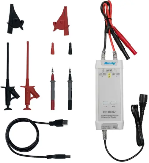
General Usage Summary
Connecting the probe: First, connect the probe’s USB power input to a USB power source such as the oscilloscope’s USB port and connect the probe’s BNC connector to an oscilloscope input. Then, set the proper attenuation rate and connect the probe input to the device st.
Disconnecting the probe: First, disconnect the probe inputs from the device under test, and then unplug the probe output and power input.
Use proper grounding: To avoid an electric shock, all devices that require
grounding must be connected to earth ground. Before making connections to the input or output terminals of the probe, ensure that the test instrument is properly grounded if necessary.
Measurement safety: Always be aware of the voltage rating of the probe and the measurement accessories you are using and of the maximum amplitude of the signal you intend to measure. Never apply a potential that exceeds the voltage ratings of the probe and/or its accessories to avoid damaging the product and creating a hazardous situation.
Only qualified personnel should perform service on this product.
Do not touch exposed connections and components when power is present.
If an over-range condition occurs, please disconnect power and signal input from the probe immediately.
Do Not Operate in an Explosive Atmosphere.
Do Not Operate in Wet/Damp Conditions.
Keep Product Surfaces Clean and Dry.
Please read this manual carefully before use!
Introduction
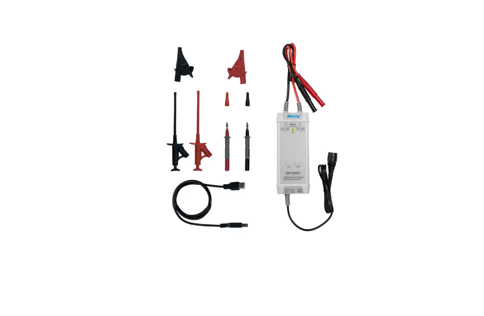
Micsig DP series differential probe can convert the input high voltage differential signal into single-ended Low-voltage signal, and display through the oscilloscope. Available with low and high attenuation option, the differential measurement voltage can reach up to 700V/ 1300V/5600V.
Specification
| Model | DP10007 | DP10013 | DP20003 |
| Bandwidth | 100MHz | 100MHz | 100MHz |
| Rise Time | ≤3.5ns | ≤3.5ns | ≤3.5ns |
| Attenuation | 10X 100X | 50X 500X | 200X 2000X |
| Gain accurecy | ±1% | ±2% | ±2% |
| Maximum Differential Test Voltage (DC+AC PK) | 70V(10X) 700V(100X) | 130V(50X) | 560V(200X) |
| Maximum input common mode voltage | CAT II 600V CAT I 1000V | CAT II 1000V | CAT Ⅲ 1000V |
| Input referred noise | ≤15mVrms(10X) ≤60mVrms(100X) | ≤40mVrms(50X) ≤230mVrms(500X) | ≤160mVrms(200X) ≤920mVrms(2000X) |
| Common Mode Rejection Ratio | ≤-80dB@50Hz ≤-50dB@1MHz ≤-60dB@20KHz ≤-40dB@10MHz | >80db(DC) >60db(100KHz) >50db(1MHz) | >80db(DC) >60db(100KHz) >50db(1MHz) |
| Input Impedance | 8MΩ/1.25pF(differential) 4MΩ/2.5pF(single-ended to ground) | 10MΩ/1pF(differential) 5MΩ/2pF(single-ended to ground) | 50MΩ/1.25pF(differential) 25MΩ/2.5pF(single-ended to ground) |
| Output Voltage | ≤7V | ≤3V | ≤3V |
| Power | 1.25W | 0.85W | 0.85W |
| Power Supply | DC 5V,USB Supply | ||
| Overrange Alarm | Button light flashes | ||
| Dimension | 14.5cm*6cm*2.7cm | ||
| Input cable length | Approx 45cm | ||
| Output cable length | Approx 90cm | ||
| Operating Temperature | 0℃~40℃ | ||
| Operating Humidity | 10%~85% | ||
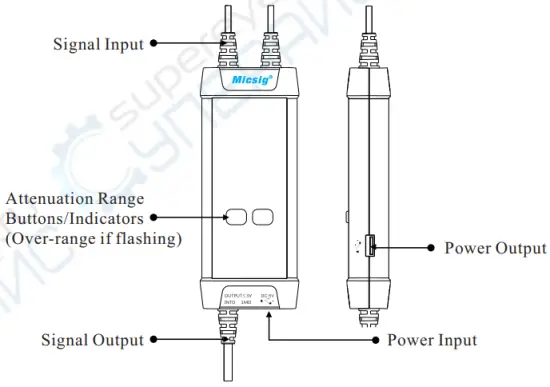
Panel Description
Making Measurements
- Powering the probe:
Connect the USB input of the probe to the USB port of the oscilloscope or a suitable USB power source. - Connecting the probe to the oscilloscope:
Connect the probe output BNC to the oscilloscope channel input.
Note: make sure the oscilloscope is properly grounded if necessary. - Set the appropriate attenuation range according to the measured voltage.
- Connecting the input to the device under test:
Using the appropriate input accessory, connect the probe to the device under test to start the measurement. If the attenuation range indicator flashes (indicating over-range), please immediately disconnect the power and input. - Set the measuring instrument.
Best Practices
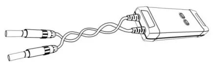
- Twisting the input leads together can help reduce noise and improve the probe’s high frequency response when measuring signals. Please view the diagram below for an example:

- Extending the input leads may introduce more noise during measurement.
If extra extension lead is necessary, please ensure the extension leads are of equal length and the input signal frequency is under 10MHz. Otherwise, measurement errors may occur. - While measuring a high frequency signal, don’t touch the end of the input lead with your hand or other objects. Otherwise, it may affect the accuracy of the measurement.
- Ensure that you use an oscilloscope with an input impedance of at least 1MΩ and bandwidth of at least 100MHz.
- Turn on the oscilloscope or externally powered instrument and let the probe and equipment warm up for 20 minutes.
- When a substantial change in temperature or other circumstances affect the accuracy of the probe’s zero point, a calibration is needed: short the input terminals of the probe, then power the probe while simultaneously pressing the Attenuation Range Buttons/Indicators for three seconds.
Warranty
Micsig warrants that this probe will be free from defects in materials and workmanship for a period of one (1) year and accessories for a period of six(6) months from the date of shipment. If any such product proves defective during this warranty period, Micsig, at its option, either will repair the defective product without charge for parts and labor, or will provide a replacement in exchange for the defective product. Parts, modules and replacement products used by Micsig for warranty work may be new or reconditioned to like new performance. All replaced parts, modules and products become the property of Micsig.
Shenzhen Micsig Instruments Co., Ltd.
Add: 1F, Bldg A, Huafeng International Robot Industrial Park,
Hangcheng Rd, Bao’an District, Shenzhen, Guangdong, China, 518126
WEB: www.micsig.com
TEL: +86-755-88600880
E-mail: [email protected]


