Confidential G Series Disc Grinder
WARNING: Before attempting disassembly, be sure to turn off the power switch and disconnect the power cord plug from the outlet.
Precautions on disassembly and reassembly
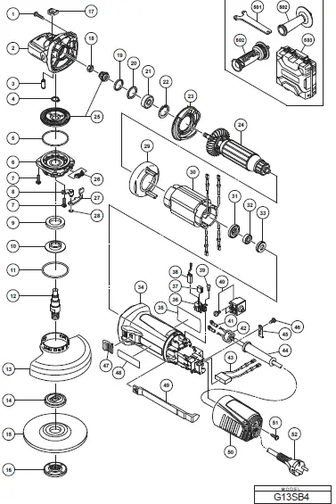
[Bold] numbers in the description below correspond to the item numbers in the parts list and exploded assembly diagram for the Models G 12SA4 and G 12SA4(S), and <Bold> numbers to those for the Models G 13SB4 and G 13SB4(S).
Disassembly
- Removal of the armature and stator
- Loosen the Tapping Screw (W/Flange) D4 x 20 [51]<51> and pull out the Tail Cover [50]<50>. Remove the Carbon Brushes (1 Pair) [38]<38> from the Brush Holders [36]<36>.
- Loosen the four Seal Lock Screws (W/Sp. Washer) M4 x 14 [7]<7> and remove the Packing Gland [6]<6> ass’y and Lever Holder [8]<8>.
- Loosen the four Tapping Screws (W/Flange) D4 x 25 [1]<1> that fix the Gear Cover [2]<2> to remove the Armature [24]<24> from the Housing [34]<34> together with the Diffuser [23]<23>. At this time, check that the Rubber Bushing [33]<33> is fitted in the housing ball bearing chamber.
- Carefully wrap the Armature [24]<24> with a soft, clean rag to protect it from being damaged, and clamp it securely in a vise. Then remove the Special Nut M7 [18]<18> and extract the Gear and Pinion Set [25]<25>.
- Disconnect the four internal wires of the Stator [30]<30> from the Pushing Button Switch [40]<40> and Brush Holders [36]<36>.
- Remove the Fan Guide [29]<29> and Stator [30]<30> from the Housing [34]<34>.
NOTE: If the Stator [30]<30> is hard to be removed from the Housing [34]<34>, heat the Housing [34]<34> up to about 60°C to facilitate removal. Then pull out the Rubber Bushing [33]<33>.- Each internal wire of the Stator [30]<30> is covered with a glass tube. Do not bend the internal wires repeatedly and do not peel off the glass tubes when removing the Stator [30]<30> from the Housing [34]<34>. Otherwise, the internal wires may be disconnected.
- Do not apply excessive force to the terminals of the Stator [30]<30> when removing them from the Pushing Button Switch [40]<40> and Brush Holders [36]<36>. Otherwise, the terminals of the Stator [30]<30> may be broken.
- Removal of the rubber bushing
Insert the special repair tool J-201 spring hook (Code No. 970977) between the Rubber Bushing [33]<33> assembled in the Housing [34]<34> and the housing ball bearing chamber, and then pull out the Rubber Bushing [33]<33>. - Removal of the dust seal
- Insert the hooks of the J-204 bearing puller between the Ball Bearing 698SS [32]<32> and the Dust Seal [31]<31> and fix the hooks with the wing bolts.
NOTE: Be careful not to insert the hooks excessively. - Put the bearing puller on an appropriate stand. Press down on the armature shaft with a hand press and pull out the Ball Bearing 698SS [32]<32>.
- Pull out the Dust Seal [31]<31> from the armature shaft.
- Insert the hooks of the J-204 bearing puller between the Ball Bearing 698SS [32]<32> and the Dust Seal [31]<31> and fix the hooks with the wing bolts.
- Removal of the gear and spindle
- Loosen the four Seal Lock Screws (W/Sp. Washer) M4 x 14 [7]<7> and remove the Packing Gland [6]<6> from the Gear Cover [2]<2>.
- Remove the Retaining Ring for D12 Shaft [4]<4> that secures the gear to the Spindle [12]<12>.
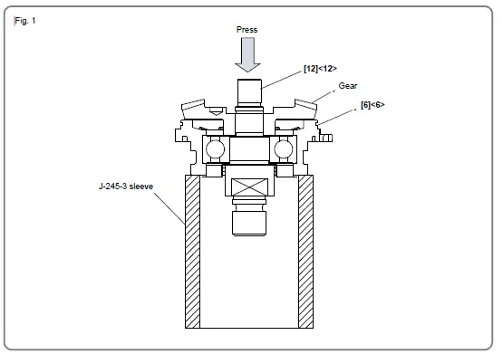
- When it is necessary to remove the gear from the Spindle [12]<12>, it is highly recommended that the special repair tool J-245-3 sleeve (Code No. 307720) described below is utilized. Place the assembly on a sleeve that matches the dimension of the Packing Gland [6]<6> and press down on the top of the Spindle [12]<12> with a hand press to remove the gear as shown in Fig. 1.

- Removal of the pushing button switch
- Disconnect the two internal wires of the Stator [30]<30> and two internal wires of the Noise Suppressor [43]<43> from the Pushing Button Switch [40]<40>.
- Remove the Cord [52]<52> from the side rib of the Housing [34]<34>.
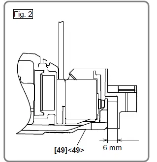
- Push the Slide Bar [49]<49> and Slide Knob [47]<47>. Leave a 6- mm gap between the Slide Bar [49]<49> and Housing [34]<34>.
Pull the Pushing Button Switch [40]<40> as shown in Fig. 2.
- Remove the Cord [52]<52> from the Pushing Button Switch [40]<40>.
Reassembly
Reverse the disassembly procedure to reassemble. Note the following points.
- Rub grease into the teeth of the Gear and Pinion Set [25]<25> with your fingers so that the grease reaches each tooth bottom. Note that under-lubricated Gear and Pinion Set [25]<25> may wear at a faster rate.
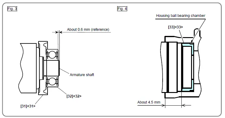
- When replacing the Armature [24]<24> and the Ball Bearing 698SS [32]<32> on the commutator side, press the Dust Seal [31]<31> in while carefully noting its direction until the end face of the Dust Seal [31]<31> contacts the butting surface of the Armature [24]<24>, and check that the Dust Seal [31]<31> cannot turn freely. (See Fig. 3.) The Dust Seal [31]<31> is an important element for improved dust protection of the Ball Bearing 698SS [32]<32>. Be sure to replace the Dust Seal [31]<31> with new one at every disassembly work. Fit the Rubber Bushing [33]<33> into the housing ball bearing chamber before installing the Armature [24]<24>. (See Fig. 4.)

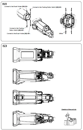
- When installing the Stator [30]<30> into the Housing [34]<34>, insert it while being careful about correctly placing the internal wires of the Stator [30]<30> as shown in Fig. 5. Connect the four internal wires of the Stator [30]<30> correctly as shown in Fig. 6.
NOTE:- Be careful not to put the internal wire of the Carbon Brush (1 Pair) [38]<38> on the top of the Brush Holders [36]<36> when connecting the internal wires of the Stator [30]<30> or when connecting the Carbon Brush (1 Pair) [38]<38>.
- Each internal wire of the Stator [30]<30> is covered with a glass tube. Do not bend the internal wires repeatedly and do not peel off the glass tubes when mounting the Stator [30]<30> to the Housing [34]<34>. Otherwise, the internal wires may be disconnected.
- Do not apply excessive force to the terminals of the Stator [30]<30> when inserting them into the Pushing Button Switch [40]<40> and Brush Holders [36]<36>. Otherwise, the terminals of the Stator [30]<30> may be broken.

- Be sure to soak the inner diameter of the Felt Packing [9]<9> with machine oil. Otherwise, its dust sealing function will fail to work properly, resulting in premature damage to the ball bearing of the Packing Gland [6]<6>. Wipe the Felt Packing [9]<9> lightly with a rag before assembling.
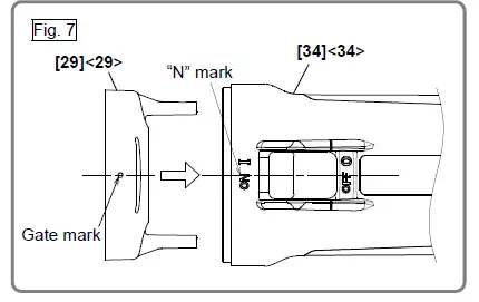
- Mount the Fan Guide [29]<29> in proper direction by matching the gate mark of the Fan Guide [29]<29> with the “N” mark of the Housing [34]<34> as show in Fig. 7.

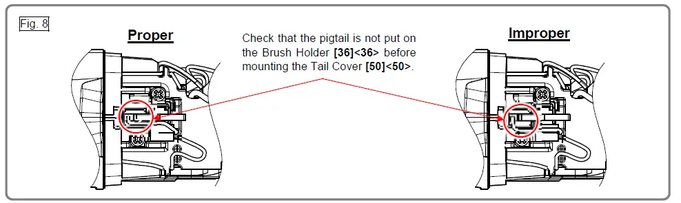
- Do not catch the pigtail of the Carbon Brush (1 Pair) [38]<38> in the Tail Cover [50]<50> when mounting the Tail Cover [50]<50>. Check that the pigtail is in its proper position as shown in Fig. 8 before mounting the Tail Cover [50]<50>.

- Tighten three of the four Seal Lock Screws (W/Sp. Washer) M4 x 14 [7]<7> except the one for securing the Lever Holder [8]<8>. Mount the Lever [27]<27> and Retaining Ring D4 [28]<28> to the Lever Holder [8]<8>. Hook the Spring [26]<26> on the Lever [27]<27>. Then tighten the remaining Seal Lock Screw (W/Sp. Washer) M4 x 14 [7]<7>.
- Mount the Pushing Button Switch [40]<40> according to the following steps.
- Attach the Cord [52]<52> to the Pushing Button Switch [40]<40>.
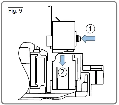
- Mount the Pushing Button Switch [40]<40> while pressing the pressing point of the Pushing Button Switch [40]<40> as shown in Fig. 9.

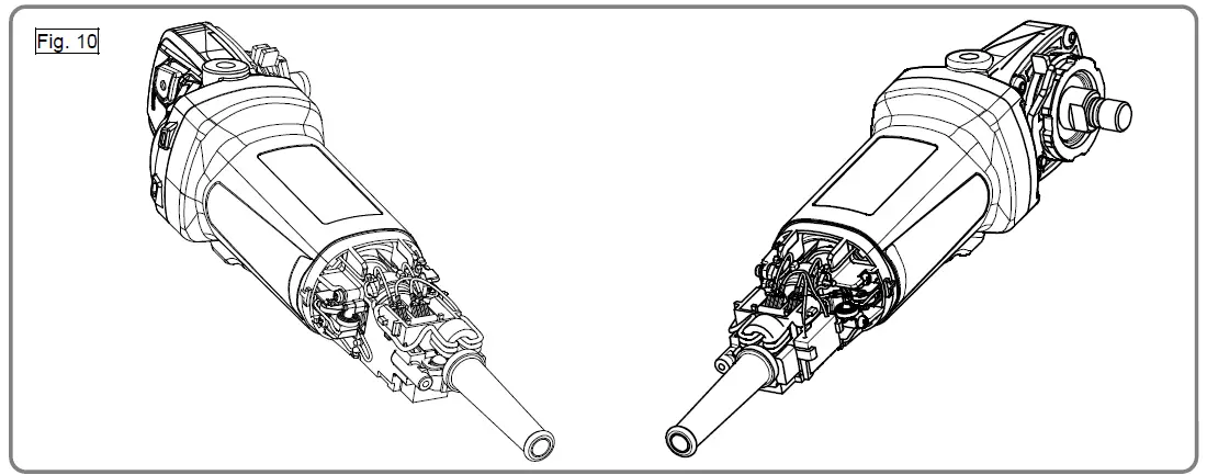
- Mount the Ferrite Core [42]<42> and Cord [52]<52> as shown in Fig. 10.

Lubrication point and type of lubricant
NOTE: Use a brush when rubbing grease.
- When replacing the Gear Cover [2]<2>, lubricate the inner circumference of the needle bearing with 0.3 g of Cosmo Molybdenum No. 1 grease.
- Rub 18 g of Cosmo Molybdenum No. 1 grease into the pinion chamber of the Gear Cover [2]<2>.
- Rub 2 g of Cosmo Molybdenum No. 1 grease into the teeth of the gear.
- Rub 0.7 g of Cosmo Molybdenum No. 1 grease into the teeth of the pinion.
Tightening torque
| Item No. | Part name | Tightening torque | ||
| N•m | lbf•ft | kgf•cm | ||
| [18]<18> | Special Nut M7 | 7.4 ± 0.5 | 5.5 ± 0.4 | 75 ± 5 |
| [7]<7> | Seal Lock Screw (W/Sp. Washer) M4 x 14 | 1.8 ± 0.4 | 1.3 ± 0.3 | 18 ± 4 |
| [39]<39> | Tapping Screw D3 x 8 | 0.74 – 0 0.25 | 0.54 – 0 0.18 | 7.5 – 0 2.5 |
| [46]<46> | Tapping Screw (W/Flange) D4 x 12 | 2.0 ± 0.5 | 1.5 ± 0.4 | 20 ± 5 |
| [51]<51> | Tapping Screw (W/Flange) D4 x 20 (Black) | 2.0 ± 0.5 | 1.5 ± 0.4 | 20 ± 5 |
Insulation test
Measure the insulation resistance and dielectric strength after reassembly.
- Insulation resistance: 7 MΩ or higher (as measured with a 500 VDC megaohm tester)
- Dielectric strength: 4,000 VAC/minute, with no abnormalities ————– 230 V to 240 V
2,500 VAC/minute, with no abnormalities ————– 120 V
No-load current value
After no-load operation for 30 minutes, the no-load current values should be as follows.
| Voltage | 120 V | 230 V | 240 V |
| Current max. | 5.0 A | 2.5 A | 2.5 A |
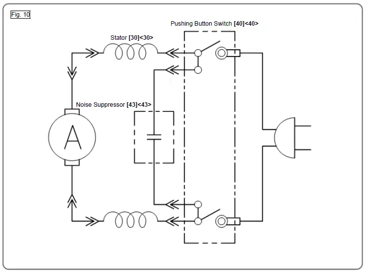
Wiring diagram
STANDARD REPAIR TIME (UNIT) SCHEDULES
| Model | Repair time | 10 | 20 | 30 | 40 | 50 | 60 min. |
| Pushing Button Switch Tail Cover Cord Cord Armor Ferrite Core | Armature Dust Seal Ball Bearing 698SS Special Nut M7 Pinion (Gear and Pinion Set) | Packing Gland Spindle Felt Packing Fringer Gear (Gear and Pinion Set) Retaining Ring for D12 Shaft O-ring Lever Holder Lever Spring Retaining Ring D4 | |||||
| G 12SA4 | Work Flow | ||||||
| Housing Stator Slide Bar Slide Switch Knob Rubber Bushing | |||||||
| G 13SB4 | |||||||
|
General Assembly | |||||||
| Brush Holder Noise Suppressor Cord Clip | |||||||
| Gear Cover Seal Ring (A) Washer (C) Ball Bearing 629VV Retaining Ring for D26 Hole Lock Pin Pushing Button Diffuser |
| ITEM NO. | CODE NO. | DESCRIPTION | NO. USED | REMARKS |
| 1 | 307028 | TAPPING SCREW (W/FLANGE) D4 X 25 (BLACK) | 4 | |
| 2 | 375889 | GEAR COVER | 1 | |
| 3 | 301943 | LOCK PIN | 1 | |
| 4 | 939542 | RETAINING RING FOR D12 SHAFT (10 PCS.) | 1 | |
| 5 | 375899 | O-RING | 1 | |
| 6 | 375887 | PACKING GLAND | 1 | |
| 7 | 376226 | SEAL LOCK SCREW (W/SP. WASHER) M4 X 14 | 4 | |
| 8 | 375894 | LEVER HOLDER | 1 | |
| 9 | 376227 | FELT PACKING | 1 | |
| 10 | 376228 | FRINGER | 1 | |
| 11 | 375900 | O-RING | 1 | |
| 12 | 375895 | SPINDLE | 1 | |
| 13 | 375904 | WHEEL GUARD | 1 | |
| 14 | 376067 | WHEEL WASHER | 1 | |
| 15 | 316822 | D. C. WHEELS 125MM A36Q (25 PCS.) | 1 | |
| 16 | 339579 | WHEEL NUT M14 | 1 | |
| 17 | 336535 | PUSHING BUTTON | 1 | |
| 18 | 301941 | SPECIAL NUT M7 | 1 | |
| 19 | 308543 | SEAL RING (A) | 1 | |
| 20 | 980866 | WASHER (C) | 1 | |
| 21 | 629VVM | BALL BEARING 629VV | 1 | |
| 22 | 939554 | RETAINING RING FOR D26 HOLE (10 PCS.) | 1 | |
| 23 | 336542 | DIFFUSER | 1 | |
| *24 | 361131E | ARMATURE 230V | 1 | |
| *24 | 361131F | ARMATURE 240V | 1 | |
| 25 | 375888 | GEAR AND PINION SET | 1 | |
| 26 | 376229 | SPRING | 1 | |
| 27 | 375892 | LEVER | 1 | |
| 28 | 6685336 | RETAINING RING D4 | 1 | |
| 29 | 336530 | FAN GUIDE | 1 | |
| 30 | 341070F | STATOR 230 V-240 V | 1 | |
| 31 | 336536 | DUST SEAL | 1 | |
| 32 | 336871 | BALL BEARING 698SS | 1 | |
| 33 | 309929 | RUBBER BUSHING | 1 | |
| 34 | 375878 | HOUSING | 1 | |
| 35 | NAME PLATE | 1 | ||
| 36 | 336537 | BRUSH HOLDER | 2 | |
| 37 | 336872 | CUSHION SPONGE | 2 | |
| 38 | 999088 | CARBON BRUSH (1 PAIR) | 2 | |
| 39 | 328210 | TAPPING SCREW D3 X 8 | 4 | |
| *40 | 376232 | PUSHING BUTTON SWITCH | 1 | |
| *40 | 376230 | PUSHING BUTTON SWITCH | 1 | FOR GBR, EUROPE(S) |
| 41 | 980063 | TERMINAL | 2 | |
| 42 | 334379 | FERRITE CORE | 1 | |
| 43 | 375898 | NOISE SUPPRESSOR | 1 | |
| 44 | 953327 | CORD ARMOR D8.8 | 1 | |
| 45 | 937631 | CORD CLIP | 1 | |
| 46 | 305720 | TAPPING SCREW (W/FLANGE) D4 X 12 | 1 | |
| 47 | 314428 | SLIDE KNOB | 1 | |
| 48 | BRAND LABEL | 1 | ||
| 49 | 375882 | SLIDE BAR | 1 | |
| 50 | 370047 | TAIL COVER | 1 | |
| 51 | 301653 | TAPPING SCREW (W/FLANGE) D4 X 20 (BLACK) | 1 | |
| *52 | 500247Z | CORD | 1 | |
| *52 | 500435Z | CORD | 1 | FOR GBR, UAE |
| *52 | 500234Z | CORD | 1 | FOR RUS, IND |
| *52 | 500439Z | CORD | 1 | FOR AUS, NZL |
| STANDARD ACCESSORIES | ||||
| 501 | 938332Z | WRENCH | 1 | |
| *502 | 994322 | SIDE HANDLE | 1 | |
| *502 | 336865 | SIDE HANDLE | 1 | FOR VIBRATION-ABSORBING |
| 503 | 376233 | CASE | 1 | |


