![]()
CONVENTIONAL DETECTORS
TECHNICAL BULLETIN
Introduction
These instructions apply to all detectors listed on this Technical Bulletin for maintaining, cleaning and testing. Failure to follow these instructions may result in the failure of the detectors to initiate an alarm condition. Hochiki America Corporation is not responsible for detectors that have been improperly maintained, cleaned, or tested.
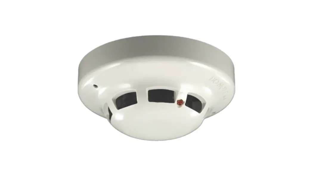
Detectors
- SOC-24V/SOC-24VN photoelectric detector suitable for monitoring smoke in open areas or HVAC ducts
- SOE-24V multi-criteria (photoelectric sensors) detector suitable for monitoring smoke in open areas or HVAC ducts
- SOE-24H multi-criteria (photoelectric/ thermistor sensors) detector suitable for monitoring smoke in open areas or HVAC ducts and fixed temperature in open areas
- DCD-135 combination heat detector suitable for monitoring fixed/rate of rise temperature in open areas
- DCD-190 combination heat detector suitable for monitoring fixed/rate of rise temperature in open areas
- DFE-135 fixed heat detector suitable for monitoring fixed temperature in open areas
- DFE-190 fixed heat detector suitable for monitoring fixed temperature in open areas
- DSC-EA rate of rise heat detector suitable for monitoring rate of rise temperature in open areas
*W or (WHT) suffix for white models not shown
Features of SOC and SOE series detectors
- High signal-to-noise ratio and sensitivity stability effective in a wide range of environmental conditions
- Wide viewing angle alarm indicators
- Automatic drift compensation and maintenance indication
- Built-in magnetic test feature
- Break-away, hidden locking feature for use with NS bases
- Optimized reduction to false alarms and enhanced reaction time to real fires
Multi-criteria Detectors use a supplementary photoelectric sensor to scale the photoelectric smoke sensor output to reduce sensitivity to false alarms and increase sensitivity to fire conditions.
Placement of Detectors
Following the guidelines in NFPA 72, base the number and location of detectors on an engineering survey of the area to be protected. Factors to consider include:
- Contents to be protected
- Type of construction and use of structure
- Human occupancy
- Burning characteristics of contents
- Space involved
- Height of ceiling
- Surface conditionthe of ceiling
- Total area
- Air movement (stratification)
- Vent location (velocities and dilution
- Deflections and obstructions
Detector Location:
- One smoke detector covers 450 to 900 square feet
- One heat detector covers up to 2500 square feet
- Consider local conditions and codes along with engineering evaluations to determine the proper spacing and specification
WARNING: Heat detectors are not life safety devices. Smoke detectors are recommended where life safety is a factor.
Examples:
- You may use 30′ spacing on smooth ceilings for all smoke detectors
- You may use 50′ spacing on smooth ceilings for DFE-135, DFE-190, and DSC-EA heat detectors
- You may use 70′ spacing on smooth ceilings for DCD-135, DCD-190 heat detectors
*Beams or other obstructions extending more than 18″ below the ceiling reduce the effective range of the detectors. Such obstruction should designate a new separation point and be considered a border for a new section.
*Beams or other obstructions extending more than 8″ but less than 18″ require reduced spacing at the perpendicular of the obstructions.
NOTE: For information on different styles of construction consult the NFPA 72.
WARNING: Do not install Hochiki smoke detectors in the following areas:
- Where temperatures are likely to exceed the operating temperature ranges specified by the detector
- Closer than 4″ to any side wall
- Where forced ventilation can dilute the smoke from a fire
- In known areas of combustion such as kitchens or furnace rooms
- In known areas of sustained corrosive atmospheres such as industrial chemical processing areas
Maintenance
Cleaning
Use clean, dry compressed air to remove dust from a detector, or return to Hochiki America for service. Disassembly of the detector may result in the failure of the detector to initiate an alarm condition or the initiation of a false alarm condition.
Testing
For a smoke detector to operate efficiently, the combustion products must enter the outer chamber. Airflow, stratification, velocity, stagnation, and migration all affect the efficiency and accuracy of the detector. Use an air flow meter to determine the movement of the air within a structure. Field testing equipment is available from Hochiki America for testing the function of the detectors. Consult local codes and ordinances for maintenance requirements. Hochiki America Corporation recommends bi-annual functional testing and visual inspection.
Prior to testing any detector, care should be exercised to ensure proper disabling of live signals and notification circuits of the Fire Alarm Control Panel. Failure to exercise this procedure may result in false alarm signals which could place life and property in jeopardy.
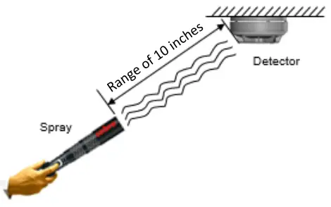
Caution: Excessive aerosol smoke can contaminate a detector.
Do not spray in bursts longer than 1 second.
Wait 20 seconds between sprays.
Spray 10 inches from the detector.
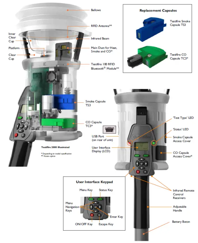
Test with Smoke Sabre aerosol cans or the Testifier 1000/1001 or 2000/2001 with TS3 smoke capsules.
Testifier usage: To insert the battery baton, hold the Testifire head unit by the handle and depress the upper spring button on the battery baton. Align the button with the location hole in the handle and push the battery baton into the handle until the button snaps into place.
- Insert the other end of the battery baton into the Solo access pole and depress the lower spring button. Align it with the location hole and push the battery baton further into the pole until the button snaps into place.
- Remove the capsule from its outer carton and Anti-Static bag.
- Remove the spring clip protector cap from the new capsule.
- Holding the capsule by spring clips with the label on the underside, carefully insert the new capsule into the capsule port. Push it into position, ensuring that the clips spring out positively on both sides of the capsule.
- Close the access cover securely.
- Program the tester to the following options available: Smoke or Heat.
- Raise Testifire over the detector. The detector should touch the base of the inner clear cup.
- Lower Testifire from the sensor after testing is complete.
| Testifire’s LED Indications | |
| Blue Solid | Smoke test in progress |
| Red Solid | Heat test in progress |
| Green Slow Flashing | Standby mode |
| Green Fast Flashing | Operational mode |
| Red Flashing | The battery needs charging, but still operational |
| Alternating Red/Green Flashing | Timeout indication (after 2 minutes of continuous testing) |
| Red Solid | Error |
SOC-24V Conventional Photoelectric Smoke Detector
| Supply Voltage | Operating Voltage Range | 8 – 35VDC |
| Absolute Max Voltage | 42VDC | |
| Maximum Voltage Ripple | Filtered DC, 15% Ripple (Max) | |
| Maximum Input Capacitance | 0.01uF | |
| Current Consumption | Standby Current | 59mA |
| Minimum Allowable Alarm Current | 6mA | |
| Maximum Allowable Alarm Current | 150mA | |
| Startup | Current | 160mA (Max) |
| Smoke Density Range | 1.36 – 3.12%/ft Open Area and 300 – 4000FPM in duct | |
| Detector Compatibility ID | HD3 | |
| Compatible Bases | NS4-100, NS6-100, NS4-220, NS6-220, NS4-221, NS6-221, NS4-224, NS6-224, HSC-220R, HSC-221R, HSC-224R, HSC-4R, HSC-4R12 *W suffix (not listed above) indicates white color | |
| Operating Temperature Range | 14F ~ 122F | |
| UL Listed Ambient Temperature | 32F ~ 100F | |
| Storage Temperature Range | -22F ~ +140F | |
| Dimensions | 3.94” diameter x 1.77” tall | |
| Color | (SOC-24V) Ivory, (SOC-24VW) White | |
| Weight | 3.0 oz. | |
| Sensing Element | Smoke | IR LED, Blue LED, Photodiode |
| Supply Voltage | Operating Voltage Range | 8 – 35VDC |
| Absolute Max Voltage | 42VDC | |
| Maximum Voltage Ripple | 8200mVAC | |
| Maximum Input Capacitance | 0.01uF | |
| Current Consumption | Standby Current | 59mA |
| Minimum Allowable Alarm Current | 5mA | |
| Maximum Allowable Alarm Current | 150mA | |
| Startup | Time | 25s (Max) |
| Current | 160mA (Max) | |
| Reset | Time | 100ms (Min) |
| Voltage | 2.5V (Max) | |
| Smoke Density Range | 1.82-3.16%/ft@ Open area 1.82-4.55%/ft@300FPM in Duct 1.82-3.96%/ft@1000FPM in Duct 1.82-4.19%/ft@2000FPM in Duct 1.82-4.07%/ft@3000FPM in Duct 1.82-4.20%/ft@4000FPM in Duct | |
| Detector Compatibility ID | HD3 | |
| Compatible Bases | NS4-100, NS6-100, NS4-220, NS6-220, NS4-221, NS6-221, NS4-224, NS6-224, HSC-220R, HSC-221R, HSC-224R, HSC-4R, HSC-4R12 *W suffix (not listed above) indicates the white color | |
| Operating Temperature Range | 32F ~ 120F | |
| UL Listed Ambient Temperature | 32F ~ 120F | |
| Storage Temperature Range | -22F ~ +140F | |
| Operating Humidity Limit | <95%RH at 104F, <80%RH at 120F | |
| Dimensions | 3.94” diameter x 1.77” tall | |
| Color | SOE-24V – Ivory, SOE-24V (WHT) – White | |
| Weight | 3.4 oz. | |
SOE-24H Conventional Photoelectric Smoke and Heat Detector
| Sensing Element | Heat | Thermistor |
| Smoke | IR LED, Blue LED, Photodiode | |
| Supply Voltage | Operating Voltage Range | 8 – 35VDC |
| Absolute Max Voltage | 42VDC | |
| Maximum Voltage Ripple | 8200mVAC | |
| Maximum Input Capacitance | 0.01uF | |
| Current Consumption | Standby Current | 59mA |
| Minimum Allowable Alarm Current | 5mA | |
| Maximum Allowable Alarm Current | 150mA | |
| Startup | Time | 25s (Max) |
| Current | 160mA (Max) | |
| Reset | Time | 100ms (Min) |
| Voltage | 2.5V (Max) | |
| Smoke Density Range | 1.80-3.16%/ft@ Open area 1.80-4.55%/ft@300FPM in Duct 1.80-3.96%/ft@1000FPM in Duct 1.80-4.19%/ft@2000FPM in Duct 1.80-4.07%/ft@3000FPM in Duct 1.80-4.20%/ft@4000FPM in Duct | |
| Heat Sensitivity Range | 135F | |
| Detector Compatibility ID | HD3 | |
| Compatible Bases | NS4-100, NS6-100, NS4-220, NS6-220, NS4-221, NS6-221, NS4-224, NS6-224, HSC-220R, HSC-221R, HSC-224R, HSC-4R, HSC-4R12 *W suffix (not listed above) indicates white color | |
| Operating Temperature Range | 32F ~ 117F | |
| UL Listed Ambient Temperature | 32F ~ 117F | |
| Storage Temperature Range | -22F ~ +140F | |
| Operating Humidity Limit | <95%RH at 104F, <80%RH at 120F | |
| Dimensions | 3.94” diameter x 2.18” tall | |
| Color | SOE-24H – Ivory, SOE-24H (WHT) – White | |
| Weight | 3.4 oz. | |
DCD-135 Conventional Fixed Temperature and Rate of rising Heat Detector
| Sensing Element | Heat | Thermistor |
| Supply Voltage | Operating Voltage Range | 15 – 33VDC |
| Absolute Max Voltage | 42VDC | |
| Maximum Voltage Ripple | Filtered DC, 5V (Max) | |
| Current Consumption | Standby Current | 35mA |
| Minimum Allowable Alarm Current | 6mA | |
| Maximum Allowable Alarm Current | 150mA | |
| Startup | Current | 160mA (Max) |
| Heat Sensitivity Range | 135F or 15F/min rise (whichever occurs first) | |
| Detector Compatibility ID | HD3 | |
| Compatible Bases | NS4-100, NS6-100, NS4-220, NS6-220, NS4-221, NS6-221, NS4-224, NS6-224, HSC-220R, HSC-221R, HSC-224R, HSC-4R *W suffix (not listed above) indicates the white color | |
| Operating Temperature Range | 14F ~ 122F | |
| UL Listed Ambient Temperature | 32F ~ 100F | |
| Storage Temperature Range | -4F ~ +140F | |
| Dimensions | 3.94” diameter x 1.5” tall | |
| Color | DCD-135 – Ivory, DCD-135W – White, DCD-135C – Ivory | |
| Weight | 3.4 oz. | |
DCD-190 Conventional Fixed Temperature and Rate of Rise Heat Detector
| Sensing Element | Heat | Thermistor |
| Supply Voltage | Operating Voltage Range | 15 – 33VDC |
| Absolute Max Voltage | 42VDC | |
| Maximum Voltage Ripple | Filtered DC, 5V (Max) | |
| Current Consumption | Standby Current | 35mA |
| Minimum Allowable Alarm Current | 6mA | |
| Maximum Allowable Alarm Current | 150mA | |
| Startup | Current | 160mA (Max) |
| Heat Sensitivity Range | 190F or 15F/min rise (whichever occurs first) | |
| Detector Compatibility ID | HD3 | |
| Compatible Bases | NS4-100, NS6-100, NS4-220, NS6-220, NS4-221, NS6-221, NS4-224, NS6-224, HSC-220R, HSC-221R, HSC-224R, HSC-4R *W suffix (not listed above) indicates the white color | |
| Operating Temperature Range | 14F ~ 122F | |
| UL Listed Ambient Temperature | 32F ~ 100F | |
| Storage Temperature Range | -4F ~ +140F | |
| Dimensions | 3.94” diameter x 1.5” tall | |
| Color | DCD-190 – Ivory, DCD-190W – White, DCD-190C – Ivory | |
| Weight | 3.4 oz. | |
DFE-135 Conventional Fixed Temperature Dry Contact Heat Detector
| Sensing Element | Heat | Bi-metal diaphragm |
| Current Consumption | Maximum Allowable Alarm Current | 100mA @ 60V |
| Heat Sensitivity Range | 135F | |
| Detector Compatibility ID | None | |
| Compatible Bases | NS6-100, HSC-220L, HSC-221L, HSC-224L *W suffix (not listed above) indicates white color | |
| Operating Temperature Range | 14F ~ 120F | |
| Storage Temperature Range | -4F ~ +140F | |
| Dimensions | 3.94” diameter x 1.5” tall | |
| Color | DFE-135 – Ivory, DFE-135W – White, DFE-135C – Ivory | |
| Weight | 3 oz. | |
DFE-190 Conventional Fixed Temperature Dry Contact Heat Detector
| Sensing Element | Heat | Bi-metal diaphragm |
| Current Consumption | Maximum Allowable Alarm Current | 100mA @ 60V |
| Heat Sensitivity Range | 190F | |
| Detector Compatibility ID | None | |
| Compatible Bases | NS6-100, HSC-220L, HSC-221L, HSC-224L *W suffix (not listed above) indicates the white color | |
| Operating Temperature Range | 14F ~ 160F | |
| Storage Temperature Range | -4F ~ +140F | |
| Dimensions | 3.94” diameter x 1.5” tall | |
| Color | DFE-190 – Ivory, DFE-190W – White, DFE-190C – Ivory | |
| Weight | 3 oz. | |
DSC-EA Conventional Rate of Rise Dry Contact Heat Detector
| Sensing Element | Heat | High Pass Diaphragm |
| Current Consumption | Maximum Allowable Alarm Current | 100mA @ 30V |
| Heat Sensitivity Range | 15F/minute | |
| Detector Compatibility ID | None | |
| Compatible Bases | HSB-100, HSC-220L, HSC-221L, HSC-224L, NS4-100, NS6-100, NS4-220, NS6- 220, NS4-221, NS6-221, NS4-224, NS6-224, HSC-4R, HSC-4R12 *W suffix (not listed above) indicates the white color | |
| Operating Temperature Range | 14F ~ 122F | |
| Storage Temperature Range | -22F ~ +158F | |
| Dimensions | 3.94” diameter x 1.3” tall | |
| Color | DSC-EA – Ivory, DSC-EAW – White | |
| Weight | 3 oz. | |
Hochiki America Corporation
7051 Village Drive, Suite 100
Buena Park, CA 90621-2268
DWG # HA-06-434, Rev 07/21
PAGE 11 of 11
PART # 1700-12470


