![]()
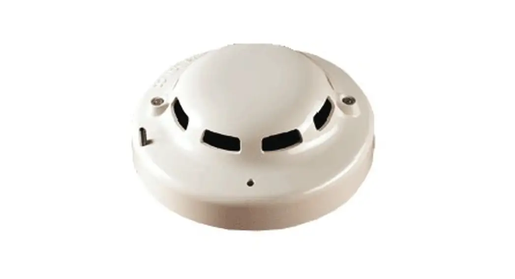
SLR-24V Photoelectric Smoke Detector
Instructions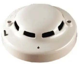
SLR-24V PHOTOELECTRIC SMOKE DETECTOR
STANDARD FEATURES
- Low profile, 1.8″ high (with base)
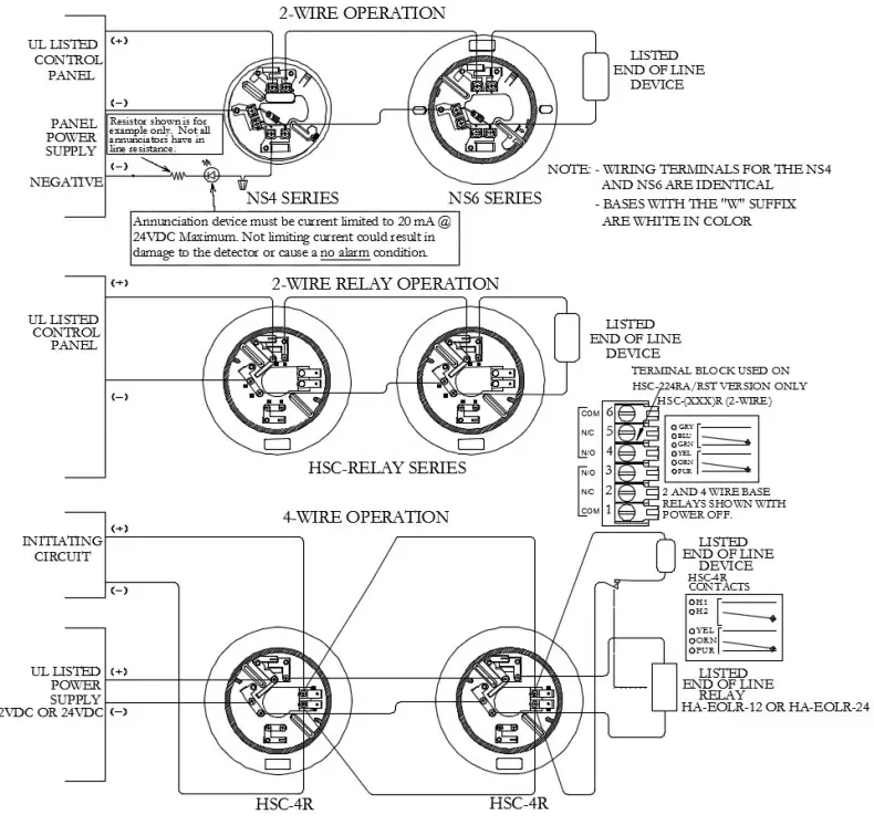
- 2 or 4 wire base compatibility, relay base available
- Highly stable operation, RF/transient protection
- Two built-in power/sensitivity supervision/alarm LEDs
- Non-directional smoke chamber
- Removable smoke labyrinth for cleaning or replacement
- The automatic Sensitivity window verification function meets outlined requirements in NFPA 72, Chapters 2 & 7 inspections, testing, and maintenance
SPECIFICATIONS
| Light Source | GaAIAs Infrared Light Emitting Diode |
| Rated Voltage | 17.7 – 30.0 VDC |
| Working Voltage | 15.0 – 33.0 VDC |
| Nominal Voltage | 24 VDC |
| Maximum Voltage | 42 VDC |
| Supervisory Current | 45µA @ 24 VDC |
| Surge Current | 160µA max. @ 24 VDC |
| Alarm Current | 150mA max. @ 24VDC |
| Air Velocity Range | 0-4000 fpm |
| Ambient Temperature | 32°F to 100°F (0°C to 49°C) |
| Maximum Humidity | 95% RH Non-condensing |
| Color & Case Material | Bone PC/ABS Blend |
| Mounting | Refer to NS Conventional Detector Base Data Sheet |
APPLICATIONS
The Hochiki SLR-24V can be used in all areas where Photoelectric
Smoke Detectors are required. The Patented smoke chamber makes the SLR-24V well suited for fires ranging from smoldering to fast-flame fires.
NS-4 Series, NS-6 Series, HSC-4R or HSC-xxxR Style bases may be used with the SLV-24V. Current interchangeable/ compatible devices are the SIJ-24 ionization detector, the SLR24H photoelectric smoke detector, and the DCD-135/190 heat detectors.
All NS conventional devices are mechanically compatible with Hochiki America HSB, HSC, and YBA type bases which may have been used in previous installations. Please check individual panel listings for compatible bases.
OPERATION
The SLR-24V photoelectric smoke detector utilizes two bicolored LEDs for indication of status. In a normal standby condition, the LEDs flash GREEN every 3 seconds. When the detector senses smoke and go into alarm the status LEDs with the latch on RED.
The detector utilizes an infrared LED light source and silicon photodiode receiving element in the smoke chamber. In a normal standby condition, the receiving element receives no light from the pulsing LED light source. In the event of a fire, smoke enters the chamber, and light is reflected from the smoke particles to the receiving element. The light received is converted into an electronic signal.
Signals are processed and compared to a reference level, and when two consecutive signals exceeding the reference level are received within a specific period of time. The time delay circuit triggers the SCR switch to activate the alarm signal. The status LEDs light continuously during the alarm period
PRODUCT LISTINGS
![]()
ENGINEERING SPECIFICATIONS
The contractor shall furnish and install Hochiki’s SLR-24V Photoelectric Smoke Detectors as indicated on the plans. The detector head and twist lock base is UL Listed and it’s compatible with a UL Listed fire alarm control panel.
The base permits direct interchange with the Hochiki SLR-24H combination photoelectric smoke with the heat sensor, SIJ-24 ionization type smoke detector, and/or DCD- 35/190 fixed temperature/rate-of-rise heat detectors.
The base shall be appropriate twist lock base NS-4 Series, NS-6 Series, HSC-4R, or HSC-xxx R. In the event of partial or complete retrofit, the SLV-24V may be used in conjunction with, or as a replacement for, Hochiki America detectors (SLK-24, SLK-24FH, and the SIH-24) on most HSB and HSC base applications.
The smoke detector shall have two flashing status LEDs for visual supervision. When the detector is in standby condition the LEDs will flash Green. When the detector is actuated, the flashing LEDs will latch on Red. The detector may be reset by actuating the control panel reset switch. The sensitivity of the detector shall be capable of being measured. To facilitate installation, the detector shall be non-polarized. Voltage and RF transient suppression techniques shall be employed in the detector to minimize false alarm potential. Auxiliary SPDT relays shall be installed where indicated. The vandal-resistant, security locking feature shall be used in those areas as indicated on the drawing. The locking feature shall be field removable when not required.
TYPICAL WIRING DIAGRAMS
![]() Hochiki America Corporation
Hochiki America Corporation
7051 Village Drive, Suite 100, Buena Park, CA 90621-2268
Phone: 714-522-2246 Fax: 714-522-2268
Technical Support: 800-845-6692
[email protected]
Find the latest revision at www.hochiki.com ![]() Hochiki America Corporation SLR-24V Photoelectric Smoke Detector
Hochiki America Corporation SLR-24V Photoelectric Smoke Detector
Specifications are subject to change without notice.


