

DETECTO 6560 Portable Wheelchair Scale

PORTABLE WHEELCHAIR SCALE TEST PROCEDURE
- A. Equipment Required
B. Scale Trim Adjustment
C. Calibration
D. Final Test

Equipment Required
- Scale under test
- Standard Hand tools
- Test Weights: Certified weights to accomplish the linearity tests
Scale Trim Adjustment
- Gain access to the junction box and remove the cover.
- Place a test weight of at least 25 percent of scale capacity on each corner, one at a time, and record each displayed weight.
- Place test weight on the corner with the highest displayed weight and adjust appropriate trim potentiometer counterclockwise until corner reading agrees with the lowest weight reading.
- Repeat Step No. 3 until all corners are within tolerance. For tolerance values, refer to the Linearity Check Table in the D. Final Test section.
- If any trim pot reaches the end of adjustment in the CCW direction then turn all potentiometers clockwise 25 turns or until a click is heard. Now turn all potentiometers counterclockwise 1 (one) turn and repeat steps 2 – 4.
- Turn the power off.
Calibration
- To begin Calibration and Setup, make sure the MEDVUE indicator is turned on.
- Next, looking at the front of the MEDVUE, remove the two screws from the left end cap and remove the end cap.
- Locate the calibration switch access hole near the bottom of the side panel, and insert a small hex wrench or tool through the access hole.
- Press and hold the calibration switch until the display changes to show SETUP in large letters at the top of the display, and SCALE in smaller letters at the bottom.
- Release the calibration switch. You are now ready to perform calibration.
- During setup and calibration, pressing the PRINT/ENTER key will cause the data displayed, to be retained and the indicator to advance to the next prompt. Change the value by entering the new data using the numeric keypad, and then pressing the PRINT/ENTER key.
- Follow the prompts listed in the MEDVUE SETUP TABLE.
| MEDVUE SETUP TABLE | |
| CAPACITY = | 1000 |
| OIML = | NO |
| UNITS = | 2 |
| INTERVAL = | 2 |
| dECIMAL = | 1 |
| MOTION RANGE = | 2 |
| SAMPLE RATE = | 2 |
| ZERO LIMIT = | no |
| POWER UP ZERO = | no |
| ZERO TRACKING = | 3 |
| FILTER MOdE = | 2 |
| FILTER LEVEL = | 0 |
| CALIbRATE = | YES |
| NUM CAL POINTS = | 1 |
| LOAdEd CAL WT = | APPLY FULL CAPACITY WEIGHT |
| UNLOAd | REMOVE TEST WEIGHTS |
| GRAVITY ENAbLE = | no |
| HOLd MOdE = | 2 |
| BANd = | 99 |
| LANGUAGE = | 0 |
| bACKLIGHT = | 150 |
| KEYPAd bEEP = | YES |
| SLEEP MOdE = | 4 |
| AUTO SHUT OFF = | 2 |
| KEY dISAbLE = | 0 |
| ENAbLE Id = | no |
| bARCOdE = | no |
| USE HEIGHT = | no |
| bOdY MASS IdX = | YES |
| HI RESOLUTION = | no |
| RS232 MOdE = | 3 |
| bAUd RATE = | 3 |
| PRINTER TYPE = | 0 |
| END OF PRINT = | 0 |
| USb MOdE = | 1 |
| YEAR [YYYY] = | Enter current year |
| MONTH [1-12] = | Enter current month |
| dAY [1-31] =. | Enter current day of the month |
| HOUR [0-23] = | Enter current hour in 24-hour format |
| MINUTE [0-59] = | Enter current minute |
| SECONd [0-59] = | Enter current second |
| 24 HOUR TIME = | no |
Final Test
- Perform Corner Test using 1/4 capacity weights (positions 1-4). Use tolerances listed in the table below.
- Perform the Linearity test. Check both ascending and descending. See the table below.
- Install indicator cover.
Linearity Check Table
| Applied Weight | Tolerance | WEIGHT POS | ||
| 0 | 0 | |||
| *200 lb | 199.8 lb | To | 200.2 lb | 1,2,3,4 |
| 400 lb | 399.8 lb | To | 400.2 lb | 1+4 Then 2+3 |
| 500 lb | 499.8 lb- | To | 500.2 lb+ | 5 |
| 900 lb | 899.4 lb | To | 900.6 lb | 5+2+3 Then 5+1+4 |

APPLICATION OF ADHESIVE/ADHESIVE-BACKED ITEMS
- Use a clean cloth or paper towel to clean the surface with alcohol where the adhesive or adhesive-backed item is to be applied.
- After the alcohol has dried, use another clean dry cloth or paper towel to wipe the surface clean of all residue before the adhesive-backed item is applied.
- Apply the adhesive-backed item immediately after the surface has dried. Be careful not to touch either the application surface or the adhesive with the bare hand.
- Using a clean dry cloth or paper towel, rub out all air bubbles on flat items, such as keypads, labels, serial tags, etc., by rubbing back and forth on the surface of the adhesive-backed item while pressing firmly.
NOTE: Be sure to press firmly on each corner to ensure a good bond. - For items that have foam tape, such as standoffs, apply the items straight to the surface and hold in place with firm pressure for 5-10 seconds.
NOTE: Most adhesive-backed items will not attain full strength until after 24 hours. The above procedure must be followed to obtain the maximum bonding strength of any adhesive.
PARTS IDENTIFICATION
Final Assembly – 0065-0680-0A
| ITEM | QTY | PART NUMBER | DESCRIPTION |
| 1 | 1 | 0065-0703-0A | UNIV. BASE ASSY 6560/6570 |
| 2 | 1 | 0065-0807-0A | 6560 COL. AND LATCH ASSY RH |
| 3 | 1 | 0065-0808-0A | 6560 COL. AND LATCH ASSY LH |
| 4 | 1 | 0065-0689-0A | 6570 HANDRAIL WELDMENT |
| 5 | 14 | 6021-1454 | 1/4-20 x .750, ZP |
| 6 | 4 | 6021-1127 | SCW PAN-HEAD, SELF-TAP…6- 32X.5 |
| 7 | 1 | 0065-0676-08 | BACK COVER PLATE, CR SHT 22 GA CQ |
| 8 | 12 | 6021-1257 | SCW, TRUSS-HEAD THREAD CUTTING, 8-32X.375 |
| 9 | 1 | MV1 | INDICATOR |
NOTES:
- Wire indicator and load cell cables as shown in the schematic. Check to make sure that none of the indicator cables or load cell cable wires are crossed, or touching where they connect to the trim board to avoid a short circuit. Route cables through available holes.
- Self-tapping screw (item 6) fastens handrail weldment (item 4) to scale. 2 ea. Self-tapping screws (item 6) are used per column (items 2 and 3).
Final Assembly – 0065-0680-0A, Front and Section A-A View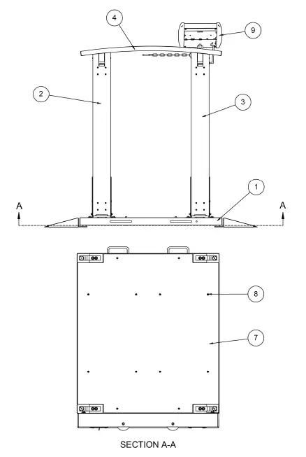
Final Assembly – 0065-0680-0A, Side, Detail B, and C View 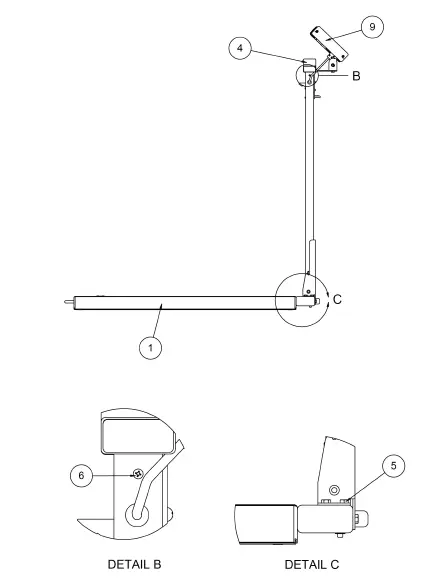
Final Assembly – 0065-0680-0A, Wiring Schematic 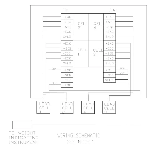
6560/6570 Universal Base Assembly – 0065-0703-0A
| ITEM | QTY | PART NUMBER | DESCRIPTION |
| 1 | 1 | 0065-0702-0A | 6560/6570 WB WELDMENT |
| 2 | 2 | 0065-B539-08 | LATCH COVER PLATE, 14 GA, SS 304 |
| 3 | 1 | 0065-0678-08 | HR BTTM BASE/DUAL COLUMN, 3 X 1-1/2 X 3/16 WALL TUBING |
| 4 | 4 | LFB-250P | LOAD CELL, SHEAR BEAM, 125 KG, NICKEL PLATED ALLOY |
| 5 | 4 | 6540-1624 | FOOT, RUBBER, BLACK |
| 6 | 2 | 0065-0675-0A | 6550 RAMP WELDMENT |
| 7 | 2 | 0044-B178-08 | HANDLE, 3/8 ROD, 304 SS |
| 8 | 8 | 6021-2063 | SCW SOCKET-HD CAP-SCREW .375-24 |
| 9 | 4 | 6021-1045 | SCW HEX-HD, MACHINE SCW, 10-32X.5 |
| 10 | 4 | 6021-1812 | SCW FLAT-HEAD.SOCKET CAP., .25-20X.438 |
| 11 | 2 | 0065-0709-08 | 1/4″ WHEEL SHAFT, SS RD 1/4X12FT 303 ONLY |
| 12 | 2 | 574R473 | WHEEL, 3’X7/8′ 1/4 BORE |
| 13 | 6 | 6021-1809 | SCW HEX-HEAD, CAP-SCREW, .375-16X.500 |
| 14 | 4 | 399R40 | PUSH NUT, 1/4″ |
| 15 | 8 | 6680-0180 | RIVET POP, BH SS 1/8 DIA x 250-312 GR |
| 16 | 2 | 6540-1627 | REC. TUBING CAP 1″ X3″ 8 GA. WALL |
| 17 | 6 | 6024-0019 | WASHER FLAT 3/8″ SS |
| 18 | 4 | 0065-0762-08 | REINFORCEMENT PLATE, HRPO SHT 12 GA. |
| 19 | 4 | 6610-5007 | CABLE CLIP 1″ x 1″ |
| 20 | 1 | 3502-C205-0A | TRIM BOARD |
| 21 | 2 | 6021-0661 | SCW PAN-HEAD, MACHINE-SCW 06-32X.250 |
| 22 | 1 | 0065-0717-08 | 6549DS2/6550 – DECK MAT, MAT – SAFTEY TRK RESILIENT BLK |
| 23 | 2 | 0065-0718-08 | 6550/6549DS – RAMP MAT MAT – SAFETY TRK RESILIENT BLK |
NOTES:
- Center and apply deck mat (item 22) and ramp mat (item 23) on top of the deck (item 1) and ramps (item 6) before assembly.
- HR BTTM base/dual-column (item 3) must be attached to the deck (item 1) before the installation of load cells (item 4).
- Apply Loctite (6560-1126) to threads of the bolt before installation.
- Ramps can be attached for alignment and positioning of load cells. Ramps will be removed with rubber mounts (item 5) left installed in load cells for calibration and packaging.
- When installing screws (item 10) into rubber mounts (item 5) for alignment purposes, be careful not to overtighten as this may shear the rubber mount.
- Ensure that screws (item10) are set aside for individual packaging.
- Ensure all wiring is routed to the trim board through available holes in stiffeners.
- Tighten load cell bolts (item 8) to 35 ft-lbs.
- Tighten screws (item 21) until snug and PCB is held firmly in place. Do not overtighten for the risk of crushing PCB.

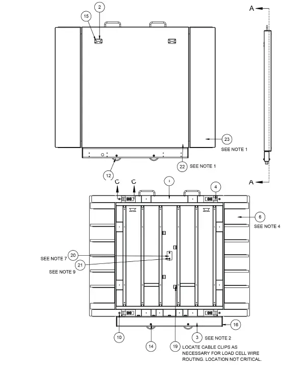
6560/6570 Universal Base Assembly – 0065-0703-0A Section A-A, Detail B, and Section C-C View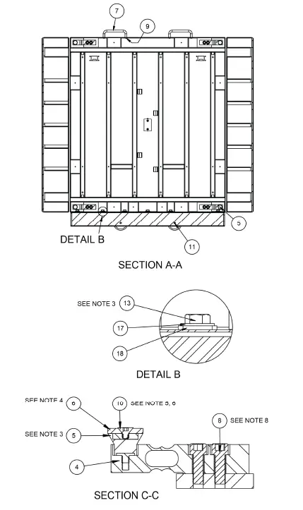
LH Column and Latch Assembly – 0065-0808-0A
| ITEM | QTY | PART NUMBER | DESCRIPTION |
| 1 | 1 | 0065-0786-0A | COLUMN WELDMENT LH – 6560 |
| 2 | 1 | 0065-0758-0A | COL. FACE SPOT WELD ASSY |
| 3 | 1 | 0065-0697-08 | 6549DS COLUMN SWIVEL BASE, SS SHT 12 GA.X48X96 |
| 4 | 1 | 0065-B342-08 | PIN – COLUMN PIVOT, SS RD 1/4 X 12 FT |
| 5 | 2 | 399R40 | PUSH NUT, 1/4″ |
| 6 | 2 | 0065-B374-08 | LATCH SPACER, POLYETHELENE .060 X 48 X 96 |
| 7 | 1 | 0065-C347-08 | GUIDE – LATCH, SS SHT 14 GA. |
| 8 | 1 | 0065-B351-08 | LINK BAR, HRPO SHT 14 GA. X 48 X 96 |
| 9 | 1 | 0031-B014-08 | SPACER, BRS TBG 1/4 OD X .025 WALL |
| 10 | 1 | 0065-B442-08 | LATCH SHAFT, SS HEX 3/8 X 12 FT |
| 11 | 1 | 0065-C443-08 | GUIDE, LATCH LOWER, SS SHT 14 GA. |
| 12 | 1 | 6022-0027 | SPRING, EXT. 1 7/8 LONG |
| 13 | 1 | 6680-0038 | WASHER FLAT #10 TYPE |
| 14 | 1 | 6021-1020 | SCW ROUND HEAD #10-32 X 0.375 |
| 15 | 1 | 0065-B373-0A | LATCH BLOCK, LOWER |
| 16 | 1 | 0065-0798-0A | LATCH WELDMENT 6570 |
| 17 | 1 | 0065-0696-08 | TRANSITION PLATE 6560, HRPO SHT 10 GA. X 48 X 96 |
| 18 | 1 | 6021-1454 | 1/4-20 x .750, ZP |
| 19 | 1 | 6024-1066 | WASHER FLAT 1/4 X 1 X 1/16 TK |
| 20 | 1 | 6680-0250 | SPACER .26 ID X .5 OD X .187 |
| 21 | 1 | 391RV204 | NUT 1/4-20 ELASTIC STOP Z/P |
| 22 | 3 | 6021-1006 | SCW SELF-TAP… 10-32X.500 S. S. |
| 23 | 1 | 6021-0950 | MACHINE SCW 10-32X1.5 |
| 24 | 1 | 6540-1053 | ENCLOSURE KNOB 1.25 DIA, 10-32 |
| 25 | 2 | 8555-C508-08 | MOUNT |
LH Column and Latch Assembly – 0065-0808-0A
| ITEM | QTY | PART NUMBER | DESCRIPTION |
| 26 | 1 | 6680-1043 | GROMMET 1/4 ID X 5/8 OD 1/8 TK |
| 27 | 1 | 0065-B403-0A | CABLE, INDICATOR |
| 28 | 1 | 6013-0295 | NUT #10-32 HEX Z/P |
| 29 | 8 | 6021-0665 | MACHINE-SCW 06-32X.375 |
| 30 | 1 | 6028-0093 | PIN HITCH |
| 31 | 1 | 6028-0094 | SPLIT RING |
| 32 | 1 | 6680-1014 | CHAIN |
NOTES:
- Apply Loctite (6560-1061) to threads of the bolt.
- Remove paint from parts as necessary for assembly.
LH Column and Latch Assembly – 0065-0808-0A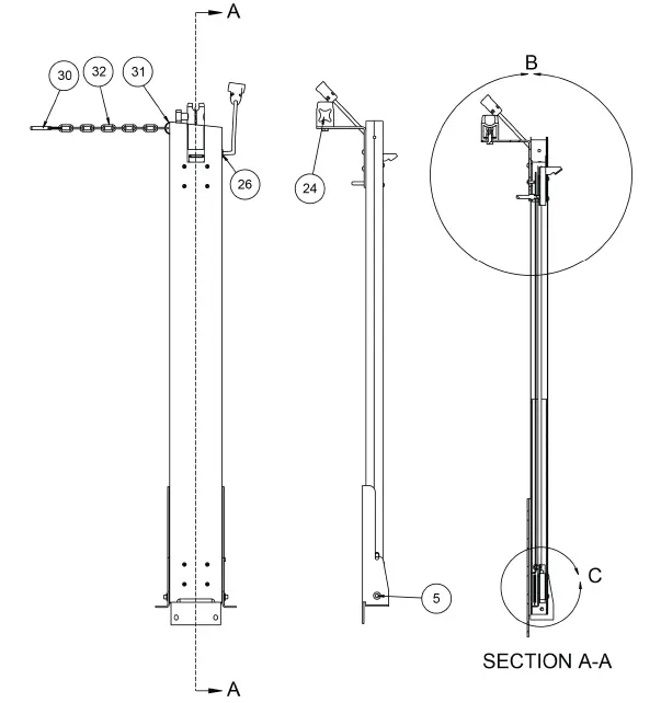
LH Column and Latch Assembly – 0065-0808-0A, Detail B and C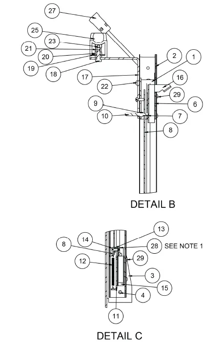
RH Column and Latch Assembly – 0065-0807-0A
| ITEM | QTY | PART NUMBER | DESCRIPTION |
| 1 | 1 | 0065-0785-0A | COLUMN WELDMENT RH – 6560 |
| 2 | 1 | 0065-0758-0A | COL. FACE SPOT WELD ASSY |
| 3 | 1 | 0065-C347-08 | GUIDE – LATCH, SS SHT 14 GA. |
| 4 | 2 | 0065-B374-08 | LATCH SPACER, POLYETHELENE .060 X 48 X 96 |
| 5 | 1 | 0065-C443-08 | GUIDE, LATCH LOWER, SS SHT 14 GA. |
| 6 | 1 | 0031-B014-08 | SPACER, BRS TBG 1/4 OD X .025 WALL |
| 7 | 1 | 0065-B442-08 | LATCH SHAFT, SS HEX 3/8 X 12 FT |
| 8 | 1 | 0065-0697-08 | 6549DS COLUMN SWIVEL BASE, SS SHT 12 GA.X48X96 |
| 9 | 1 | 0065-B373-0A | LATCH BLOCK, LOWER |
| 10 | 1 | 0065-B351-08 | LINK BAR, HRPO SHT 14 GA. X 48 X 96 |
| 11 | 1 | 6022-0027 | SPRING, EXT. 1 7/8 LONG |
| 12 | 1 | 6680-0038 | WASHER FLAT #10 TYPE |
| 13 | 1 | 6021-1020 | SCW ROUND HEAD #10-32 X 0.375 |
| 14 | 1 | 0065-B342-08 | PIN – COLUMN PIVOT, SS RD 1/4 X 12 FT |
| 15 | 2 | 399R40 | PUSH NUT, 1/4″ |
| 16 | 1 | 0065-0798-0A | LATCH WELDMENT 6570 |
| 17 | 3 | 6021-1006 | SCW 10-32X.500 S. S. |
| 18 | 1 | 6013-0295 | NUT #10-32 HEX Z/P |
| 19 | 8 | 6021-0665 | MACHINE-SCW 06-32X.375 |
| 20 | 1 | 0065-0695-08 | LATCH COVER 6560, HRPO SHT 12 GA. X 48 X 96 |
NOTES:
- Apply Loctite (6560-1061) to threads of the bolt.
- Remove paint from parts as necessary for assembly.
RH Column and Latch Assembly – 0065-0807-0A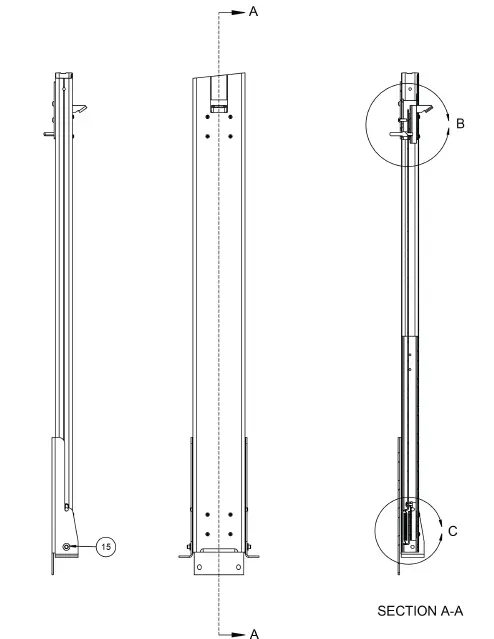
RH Column and Latch Assembly – 0065-0807-0A, Detail B and C 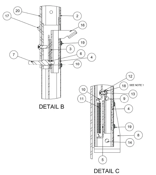
CARE AND CLEANING
Indicator
The indicator contains no user-serviceable parts and maintenance should be limited to an occasional cleaning and battery replacement as required.
General Cleaning Instructions
- Do not submerge the scale or indicator in water, pour, or spray water directly on them to clean. The scale and indicator are not waterproof and covering them with water will damage them and void the warranty.
- Always remove power before cleaning.
- When cleaning, use only damp soft cloths or plastic scouring pads for cleaning cloth and a mild non-abrasive detergent.
- DO NOT use acetone, thinner, or other volatile solvents for cleaning.
- DO NOT use things that will scratch the surface, such as steel pads, wire brushes, and scrapers.
Powder Painted Steel Care and Cleaning
While powder-painted steel is attractive and so durable that it will last many years longer than ordinary painted steel, it is desirable to clean it thoroughly on a routine basis. Three basic things should be remembered when cleaning powder-painted steel.
- Do not use wire brushes, abrasives, or cleaning tools such as steel pads and scrapers, which will scratch the painted surface. Instead, use soft cloths or plastic scouring pads for cleaning. Clean food equipment frequently to avoid build-up.
- When possible, use treated water. Hard water can leave behind deposits. Soft water is much gentler on the painted steel’s surface.
- Avoid the use of acetone, thinner or other volatile solvents, and abrasive type cleaners for cleaning. If required, a mild solvent such as mineral spirits can be used to remove oil, grease, tars, wax, and similar substances. Use a cloth dampened with mineral spirits and apply only to areas that are contaminated. Follow up the use of this mild solvent with detergent cleaning and rinsing.
STATEMENT OF LIMITED WARRANTY
Detecto Scale warrants its equipment to be free from defects in material and workmanship as follows: Detecto warrants to the original purchaser only that it will repair or replace any part of equipment which is defective in material or workmanship for a period of two (2) years from date of shipment. Detecto shall be the sole judge of what constitutes a defect.
During the first ninety (90) days Detecto may choose to replace the product at no charge to the buyer upon inspection of the returned item.
After the first ninety (90) days, upon inspection of the returned item, Detecto will repair or replace it with a remanufactured product. The customer is responsible for paying for the freight both ways.
This warranty does not apply to peripheral equipment not manufactured by Detecto; this equipment will be covered by certain manufacturers’ warranty only.
This warranty does not include the replacement of expendable or consumable parts. This does not apply to any item which has deteriorated or damaged due to wear, accident, misuse, abuse, improper line voltage, overloading, theft, lightning, fire, water or acts of God, or due to extended storage or exposure while in purchaser’s possession. This warranty does not apply to maintenance service. Purchased parts will have a ninety (90) day repair or replacement warranty only.
Detecto may require the product to be returned to the factory; item(s) must be properly packed and shipping charges prepaid. A return authorization number must be obtained for all returns and marked on the outside of all returned packages.
Detecto accepts no responsibility for items lost or damaged in transit.
Conditions Which Void Limited Warranty
This warranty shall not apply to equipment which:
- Has been tampered with, defaced, mishandled or has had repairs and modifications not authorized by Detecto.
- Has had serial number altered, defaced, or removed.
- Has not been properly grounded according to Detecto’s recommended procedure.
Freight Carrier Damage
Claims for equipment damaged in transit must be referred to the freight carrier in accordance with freight carrier regulations.
This warranty sets forth the extent of our liability for breach of any warranty or deficiency in connection with the sale or use of the product. Detecto will not be liable for consequential damages of any nature, including but not limited to, loss of profit, delays or expenses, whether based on tort or contract. Detecto reserves the right to incorporate improvements in material and design without notice and is not obligated to incorporate improvements in equipment previously manufactured.
The foregoing is in lieu of all other warranties, express or implied including any warranty that extends beyond the description of the product including any warranty of merchantability or fitness for a particular purpose. This warranty covers only those Detecto products installed in the forty-eight (48) contiguous continental United States.
FCC COMPLIANCE STATEMENT
This equipment generates uses and can radiate radio frequency and if not installed and used in accordance with the instruction manual, may cause interference to radio communications. It has been tested and found to comply with the limits for a Class A computing device pursuant to Subpart J of Part 15 of FCC rules, which are designed to provide reasonable protection against such interference when operated in a commercial environment. Operation of this equipment in a residential area may cause interference in which case the user will be responsible to take whatever measures necessary to correct the interference. You may find the booklet “How to Identify and Resolve Radio-TV Interference Problems” prepared by the Federal Communications Commission helpful. It is available from the U.S. Government Printing Office, Washington, D.C. 20402. Stock No. 001-000-00315-4.
PROPER DISPOSAL
When this device reaches the end of its useful life, it must be properly disposed of. It must not be disposed of as unsorted municipal waste. Within the European Union, this device should be returned to the distributor from where it was purchased for proper disposal. This is in accordance with EU Directive 2002/96/EC. Within North America, the device should be disposed of in accordance with the local laws regarding the disposal of waste electrical and electronic equipment.
It is everyone’s responsibility to help maintain the environment and to reduce the effects of hazardous substances contained in electrical and electronic equipment on human health. Please do your part by making certain that this device is properly disposed of. The symbol shown to the right indicates that this device must not be disposed of in unsorted municipal waste programs.
COPYRIGHT
All rights reserved. Reproduction or use, without expressed written permission, of editorial or pictorial content, in any manner, is prohibited. No patent liability is assumed with respect to the use of the information contained herein.
DISCLAIMER
While every precaution has been taken in the preparation of this manual, the Seller assumes no responsibility for errors or omissions. Neither is any liability assumed for damages resulting from the use of the information contained herein. All instructions and diagrams have been checked for accuracy and ease of application; however, success and safety in working with tools depend to a great extent upon the individual accuracy, skill, and caution. For this reason, the Seller is not able to guarantee the result of any procedure contained herein. Nor can they assume responsibility for any damage to property or injury to persons occasioned from the procedures. Persons engaging in the procedures do so entirely at their own risk.


