![]()
Cellular On Bus Module (COB) Modulo
Model: RP512ECOB
Installation and User Guide
For more information about RISCO Group’s branches, distributors and full product line, please visit riscogroup.com
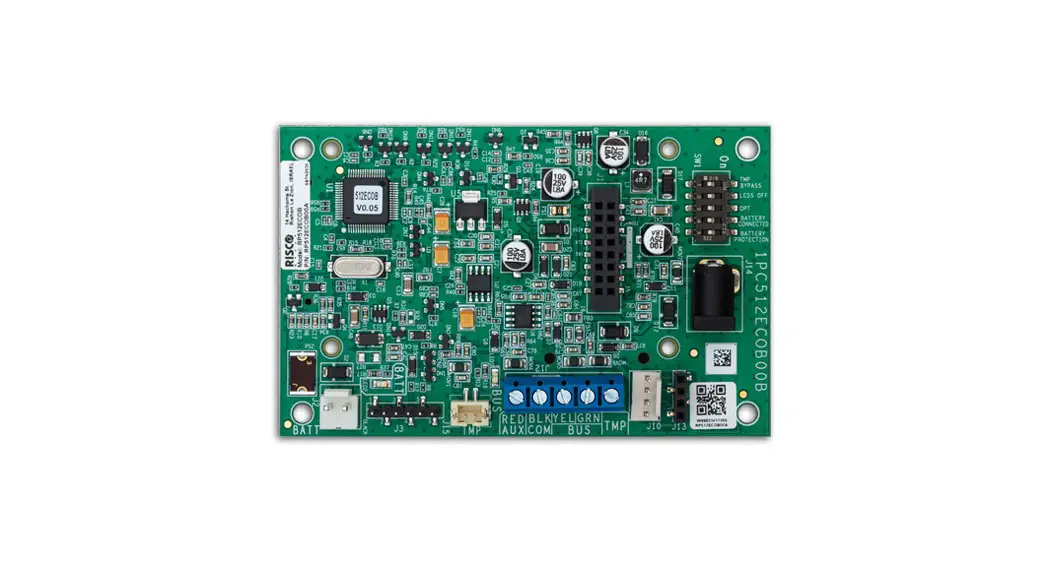
Description
The Cellualr on Bus Module (COB) is an interface between the Control Panel and GSM Module via the RS485 Bus. It enables the positioning of the GSM Module to provide improved cellular signal for when the panel is installed in a location where signal is low. This is achieved by locating the GSM Module at a location with good reception signal.
COB supports
- 2G/3G and LTE plug-in modules
- Cloud connectivity
- MS reports (IP Receiver)
- Multiple socket
- Remote panel configuration
- Remote FW upgrade of main board and accessories
- Follow-me reports (e-mails) *
- SMS
Note: Refer to the Diagnostics section and perform the System and Transmission tests to determine between mounting the COB Module in the B5
Box or in the Light SYS Box.
Installation
Preliminary Considerations
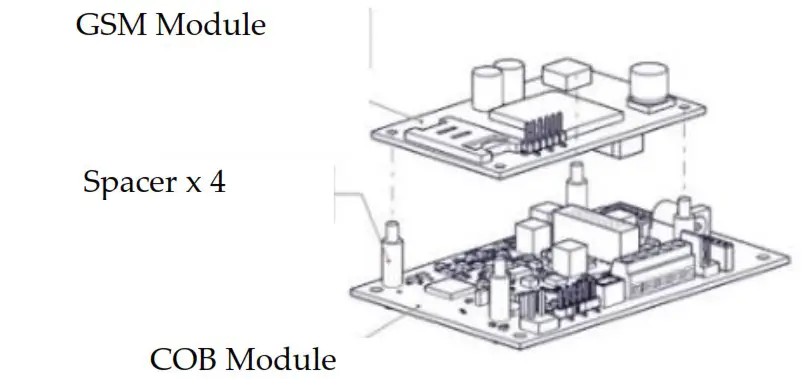
Fig. 1
Insert the 4 spacers in the holes on the COB Module
Mount the GSM Module on the 4 spacers attached to the COB module.
The COB can be mounted as a separate unit (B5 Box, Model PROSYS B5) with its own plastic housing or as a module inside the Light SYS Box
(Model RP432B) main enclosure. To determine the correct installation to perform, refer to the Diagnostics section.
The Bus communication with the Control Panel is established through a wired RS485 Bus.
The COB does not support reporting by Voice
COB Mounting in PROSYS B5 Box
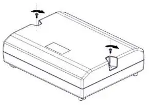
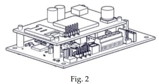
Fig. 3
Release the 2 screws on the B5 box front cover and remove the front cover.
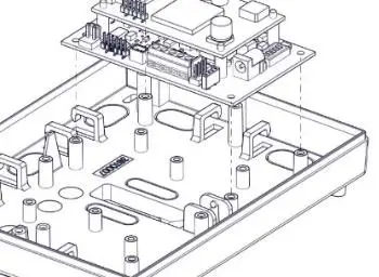
Fig. 4
Break one of the knockouts on the B5 box for the wiring. With the COB mounted on the GSM module, align the holes on the unit with the pins on the B5 box.
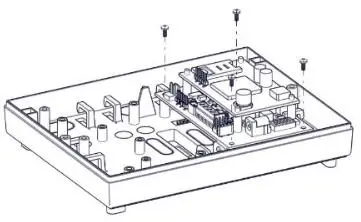
Fig. 5
Secure the unit with four screws.
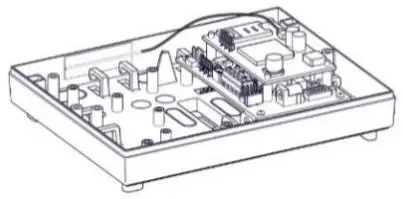
Fig. 6
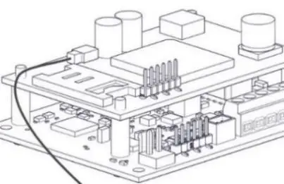 Fig. 7
Connect the antenna wire to its connector on the GSM Module (Figures 6 and 7).
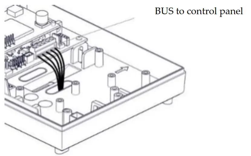
Fig. 8
Wire as in illustration.
Wire tamper to TMP and COM
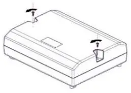
Fig. 10
Put back the B5 box front cover and secure with 2 screws.
COB Mounting in RP432B Light SYS Box
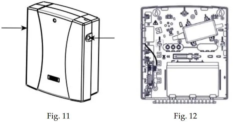
Press the circular locking plastic brackets on either side to release the front cover.
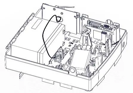
Fig. 13
a) Insert the 2 upper holes on the COB Tamper for LightSYS Housing (Model: RP432TMPCOB) into the pins on the LightSYS box.
b) Slide the tamper mechanism (from the right) onto the placement struts and click into place. Following installation of the RP432B LightSYS box on a wall, make sure to secure the back-tamper switch with a screw. c) with the GSM Module mounted on the COB module, insert the 2 upper holes on the unit into the pins on the LightSYS box, as shown.
Note: When installing COB Tamper for LightSYS Housing (Model: RP432TMPCOB), you must replace the existing sticker and in its place paste
the sticker 5STN2872 included in the kit.
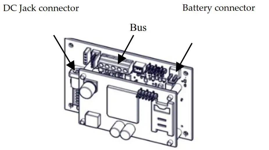 Fig. 14
Connect the battery and transformer to the battery and DC jack connectors on the COB module.
Connect the antenna wire to its connector on the GSM Module.
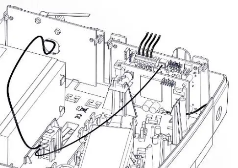
Fig. 16
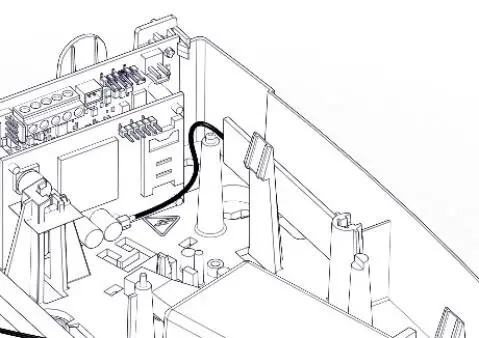
Connect the tamper wire to the J15 tamper connector.
Wire as in illustration.
Push down the front cover until the circular locking plastic brackets lock into place.
Allocating the COB
Allocation of the COB module to the system can be performed manually or automatically via the keypad.
Note: If the GSM module was removed from the unit, it is recommended to delete the GSM from the system before allocating the COB module.
Manual Allocation:
- From the installer Programming menu, select Install → BUS Device → Manual (7 → 1 → 2), scroll to COB (15), and then press OK (
 ).
). - Press the
 button to toggle to Type=COB, and then press OK ( ).
 - Go back to Manual (2) by pressing the back
 button.
 - From the Manual (2) menu, press the back button twice.
- Scroll to exit (0) and then press OK ( ).
- When Do you want to save data Y/N is displayed on the keypad, press the button (to select Y) to save changes
Automatic Allocation:
- From the installer Programming menu, select Install → BUS Device → Automatic (7→ 1→ 1), and then press OK ( ).
The Control Panel performs a scan of all the Bus devices in the system. - Press OK ( ) repeatedly to view the system’s Bus Devices while making sure that the new discovered COB device is also displayed.
- When you return to Automatic (1) menu, press the back button twice.
- Press 0 to exit, toggle to Y to save all your programming settings, and then press OK ( ).
Deleting the COB
Deleting the COB module from the system can be performed manually or automatically via the keypad.
Manual Deletion:
- From the installer Programming menu, select Install → BUS Device → Manual (7→ 1→ 2), scroll to COB (15), and then press OK ( ).
- Press the button to toggle to TYPE=NONE (to cancel its allocation), and then press OK ( ).
- Go back to Manual (2) by pressing the back button.
- From the Manual (2) menu, press the back button twice.
- Scroll to exit (0) and then press OK ( ).
- When Do you want to save data Y/N is displayed on the keypad, press the button (to select Y) to save changes.
Automatic Deletion:
- From the installer Programming menu, select Install → BUS Device → Automatic (7→ 1→ 1), and then press OK ( ).
- When EXIST is displayed on the keypad, press OK ( ).
- Press the button to toggle to TYPE=NONE (to cancel its allocation), and then press OK ( ).
- From the Automatic (1) menu, press the back button twice.
- Scroll to exit (0) and then press OK ( ).
- When Do you want to save data Y/N is displayed on the keypad, press the button (to select Y) to save changes
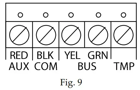
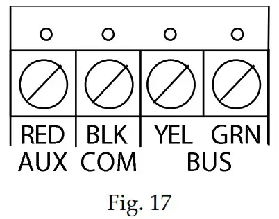
BUS Connection
| Terminal | Description |
| TMP | Tamper terminal |
| BUS GRN | Data Bus connection |
| BUS YEL | Data Bus connection |
| COM BLK | 0V common connect, connect to COM of the Light SYS/Pro SYS Plus Control Panel |
| AUX RED | 13.8Vdc power, connected to AUX or the Light SYS/Pro SYS Plus Control Panel |
Dipswitch Settings
Note: All switches must be positioned before powering up.
| SW | Description | ON | OFF (default) |
| SW1 | Tamper Bypass | Tamper bypass activated | Tamper bypass deactivated |
| SW2 | LED ON / OFF | LED OFF | LED ON |
| SW3 | Optional | – | – |
| SW4 | Battery connection | Battery connected | Battery disconnected |
| SW5 | Battery protection | Battery protected | Battery not protected |
Diagnostics
It is required to activate tests for system diagnosis to determine whether to use the supplied backup battery or power supply.
System Test
Perform this test to receive the level of the main panel’s backup battery and the installed power supplied expanders.
Go to: installer Maintenance menu → Diagnostics → COB → Main Power – Press OK to start the test; the result displays:
| Displayed Result | Action |
| < 9V | Connect the battery* and power supply |
| > 9V | Perform the Transmission test |
* Move battery Dip Switch to ON
Note: After a battery replacement/removal, it can take up to 4 minutes for the trouble to restore/appear and for the battery voltage level to be updated.
Transmission Test
Notes:
- Before performing this test, make sure that the GSM Module is physically installed and registered in the system.
- During the test, the GSM Module closes all open connections and sockets (cloud, FM, MS).
Go to: installer Maintenance menu → Diagnostics → COB → Tx voltage test – Press OK to start the test; the message ‘PLEASE WAIT..’ will appear during the 20-second test and the result will appear upon completion of the test.
| Displayed Result | Action |
| < 12V | Connect the battery* and power supply |
| > 12V – 13.5V | Connect the battery* |
| > 13.5V | Use the B5 Box (battery and power supply is not required) |
* Move battery Dip Switch to ON
LED Status
| LED | Color | Indication | Condition | |
| LED1 | Communication | Green | Bus Comm Status | OFF: No communication Fast blinking: When receiving data (communication) |
| LED2 | Battery | Red | Battery Status | OFF: Battery voltage > 11.2V or no battery Slow blink: Battery voltage between 7V to 11.2V On: Battery voltage < 7V |
Technical Specifications
| Parameter | Description |
| Current Consumption: | 13.8v +/-10%, 48mA typical/120mA max. |
| Main Panel Connection | 4-wire BUS, up to 300 m (1000 ft) from Main Panel |
| Operating temperature: | -10°C to 55°C (14°F to 131°F) |
| Storage temperature: | -20°C to 60°C (-4°F to 140°F) |
| Humidity Range | Average relative humidity: 75% |
Standard Compliance
EN50131 Grade 3, Environmental class II, RP432B EN50131-6 Type A,
EN50136-1, EN50136-2 and EN50131-10, Pro SYS B5 SPT Type X and
RP432B SPT type Y ,PD6662:2017.
RP432B Battery Type and Capacity : Lead acid battery 12V 7Ah
RP432B Low Voltage Threshold :11.1V
RP432B Deep Discharge Protection Threshold: 8.7±0.4V
SP5-One GSM 2G/3G/4G
Method of operation: Pass-through
Compatibility with Serial interface with AS
Compatibility with GPRS protocol
RED Compliance Statement:
Hereby, RISCO Group declares that this equipment is in compliance with the essential requirements and other relevant provisions of Directive 2014/53/EU. For the CE Declaration of Conformity please refer to our website: www.riscogroup.com.
Standard Limited Product Warranty (“Limited Warranty”)
RISCO Ltd. (“RISCO”) guarantee RISCO’s hardware products (“Products”) to be free from defects in materials and workmanship when used and stored under normal conditions and in accordance with the instructions for use supplied by RISCO, for a period of (i) 24 months from the date of delivery of the Product (the “Warranty Period”). This Limited Warranty covers the Product only within the country where the Product was originally purchased and only covers Products purchased as new.
Contact with customers only. This Limited Warranty is solely for the benefit of customers who purchased the Products directly from RISCO or from an authorized distributor of RISCO. RISCO does not warrant the Product to consumers and nothing in this Warranty obligates RISCO to accept Product returns directly from end users who purchased the Products for their own use from RISCO’s customer or from any installer of RISCO, or otherwise provide warranty or other services to any such end user directly. RISCO’s authorized distributor or installer shall handle all interactions with its end users in connection with this Limited Warranty. RISCO’s authorized distributor or installer shall make no warranties, representations, guarantees or statements to its end users or other third parties that suggest that RISCO has any warranty or service obligation to, or any contractual privy with, any recipient of a Product. Remedies. In the event that a material defect in a Product is discovered and reported to RISCO during the Warranty Period, RISCO shall accept return of the defective Product in accordance with the below RMA procedure and, at its
option, either (i) repair or have repaired the defective Product, or (ii) provide a replacement product to the customer.
Return Material Authorization. In the event that you need to return your Product for repair or replacement, RISCO will provide you with a Return
Merchandise Authorization Number (RMA#) as well as return instructions. Do not return your Product without prior approval from RISCO. Any Product returned without a valid, unique RMA# will be refused and returned to the sender at the sender’s expense. The returned Product must be accompanied with a detailed description of the defect discovered (“Defect Description”) and must otherwise follow RISCO’s then-current RMA procedure published in RISCO’s website at www.riscogroup.com in connection with any such return. If RISCO determines in its reasonable discretion that any Product returned by customer conforms to the applicable warranty (“Non-Defective Product”), RISCO will notify the customer of such determination and will return the applicable Product to customer at customer’s expense. In addition, RISCO may propose and assess customer a charge for testing and examination of NonDefective Product.
Entire Liability. The repair or replacement of Products in accordance with this Limited Warranty shall be RISCO’s entire liability and customer’s sole and exclusive remedy in case a material defect in a Product is discovered and reported as required herein. RISCO’s obligation and this Limited Warranty are contingent upon the full payment by customer for such Product and upon a proven weekly testing and examination of the Product functionality.
Limitations. This Limited Warranty is the only warranty made by RISCO with respect to the Products. The warranty is not transferable to any third party. To the maximum extent permitted by applicable law, this Limited Warranty shall not apply and will be void if: (i) the conditions set forth above are not met (including, but not limited to, full payment by customer for the Product and a proven weekly testing and examination of the Product functionality); (ii) if the Products or any part or component thereof: (a) have been subjected to improper operation or installation; (b) have been subject to neglect, abuse, willful damage, abnormal working conditions, failure to follow RISCO’s instructions (whether oral or in writing); (c) have been misused, altered, modified or repaired without RISCO’s written approval or combined with, or installed on products, or equipment of the customer or of any third party; (d) have been damaged by any factor beyond RISCO’s reasonable control such as, but not limited to, power failure, electric power surges, or unsuitable third party components and the interaction of software therewith or (e) any failure or delay in the performance
of the Product attributable to any means of communication provided by any third party service provider, including, but not limited to, GSM interruptions, lack of or internet outage and/or telephony failure. BATTERIES ARE EXPLICITLY EXCLUDED FROM THE WARRANTY AND RISCO SHALL NOT BE HELD RESPONSIBLE OR LIABLE IN RELATION THERETO, AND THE ONLY WARRANTY APPLICABLE THERETO, IF ANY, IS THE BATTERY MANUFACTURER’S WARRANTY. RISCO does not install or integrate the Product in the end user’s security system and is therefore not responsible for and cannot guarantee the performance of the end user’s security system which uses the Product or which the Product is a component of.
This Limited Warranty applies only to Products manufactured by or for RISCO. Further, this Limited Warranty does not apply to any software (including operating system) added to or provided with the Products or any third-party software, even if packaged or sold with the RISCO Product. Manufacturers, suppliers, or third parties other than RISCO may provide their own warranties, but RISCO, to the extent permitted by law and except as otherwise specifically set forth herein, provides its Products “AS IS”. Software and applications distributed or made available by RISCO in conjunction with the Product (with or without the RISCO brand), including, but not limited to system software, as well as P2P services or any other service made available by RISCO in relation to the Product, are not covered under this Limited Warranty. Refer to the Terms of Service at: https://riscocloud.com/ELAS/WebUI/UserLogin/License for details of your rights and obligations with respect to the use of such applications, software or any service. RISCO does not represent that the Product may not be compromised or circumvented; that the Product will prevent any personal injury or property loss by burglary, robbery, fire or otherwise, or that the Product will in all cases provide adequate warning or protection. A properly installed and maintained alarm may only reduce the risk of a burglary, robbery or fire without warning, but it is not insurance or a guarantee that such will not occur or will not cause or lead to personal injury
or property loss. CONSEQUENTLY, RISCO SHALL HAVE NO LIABILITY FOR ANY PERSONAL INJURY, PROPERTY DAMAGE OR OTHER LOSS BASED ON ANY CLAIM AT ALL INCLUDING A CLAIM THAT THE PRODUCT FAILED TO GIVE WARNING.
EXCEPT FOR THE WARRANTIES SET FORTH HEREIN, RISCO AND ITS LICENSORS HEREBY DISCLAIM ALL EXPRESS, IMPLIED OR STATUTORY, REPRESENTATIONS, WARRANTIES, GUARANTEES, AND CONDITIONS WITH REGARD TO THE PRODUCTS, INCLUDING BUT NOT LIMITED TO ANY REPRESENTATIONS, WARRANTIES, GUARANTEES, AND CONDITIONS OF MERCHANTABILITY, FITNESS FOR A PARTICULAR PURPOSE, TITLE AND WARRANTIES AGAINST HIDDEN OR LATENT
DEFECTS, TO THE EXTENT PERMITTED BY LAW. WITHOUT LIMITING THE GENERALITY OF THE FOREGOING, RISCO AND ITS LICENSORS DO NOT REPRESENT OR WARRANT THAT: (I) THE OPERATION OR USE OF THE PRODUCT WILL BE TIMELY, SECURE, UNINTERRUPTED OR ERRORFREE; (ii) THAT ANY FILES, CONTENT OR INFORMATION OF ANY KIND THAT MAY BE ACCESSED THROUGH THE PRODUCT SHALL REMAIN SECURED OR NON DAMAGED. CUSTOMER ACKNOWLEDGES THAT NEITHER RISCO NOR ITS LICENSORS CONTROL THE TRANSFER OF DATA OVER COMMUNICATIONS FACILITIES, INCLUDING THE INTERNET, GSM OR OTHER MEANS OF COMMUNICATIONS AND THAT RISCO’S PRODUCTS, MAY BE SUBJECT TO LIMITATIONS, DELAYS, AND OTHER PROBLEMS INHERENT IN THE USE OF SUCH MEANS OF COMMUNICATIONS. RISCO IS NOT RESPONSIBLE FOR ANY DELAYS, DELIVERY FAILURES, OR OTHER DAMAGE RESULTING FROM SUCH PROBLEMS. RISCO WARRANTS THAT ITS PRODUCTS DO NOT, TO THE BEST OF ITS KNOWLEDGE, INFRINGE UPON ANY PATENT, COPYRIGHT, TRADEMARK, TRADE SECRET OR OTHER INTELLECTUAL PROPERTY RIGHT IN ANY EVENT RISCO SHALL NOT BE LIABLE FOR ANY AMOUNTS REPRESENTING LOST REVENUES OR PROFITS, PUNITIVE DAMAGES, OR FOR ANY OTHER INDIRECT, SPECIAL, INCIDENTAL, OR CONSEQUENTIAL DAMAGES, EVEN IF THEY WERE FORESEEABLE OR RISCO HAS BEEN INFORMED OF THEIR POTENTIAL.
© RISCO Group 07/2021
5IN2671 F


