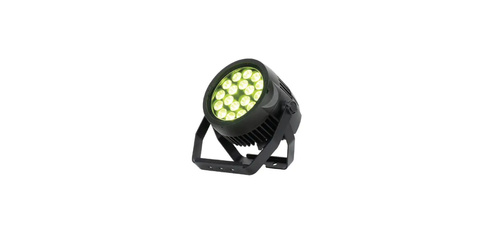
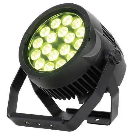
ADJ ENCORE LP18IP outdoor fixture light
©2022 ADJ Products, LLC all rights reserved. Information, specifications, diagrams, images, and instructions herein are subject to change without notice. ADJ Products, LLC logo and identifying product names and numbers herein are trademarks of ADJ Products, LLC. Copyright protection claimed includes all forms and matters of copyrightable materials and information now allowed by statutory or judicial law or hereinafter granted. Product names used in this document may be trade-marks or registered trademarks of their respective companies and are hereby acknowledged. All non-ADJ Products, LLC brands and product names are trademarks or registered trademarks of their respective companies. ADJ Products, LLC and all affiliated companies hereby disclaim any and all liabilities for property, equipment, building, and electrical damages, injuries to any persons, and direct or indirect economic loss associated with the use or reliance of any information contained within this document, and/or as a result of the improper, unsafe, insufficient and negligent assembly, installation, rigging, and operation of this product.
INTRODUCTION
Unpacking:
Thank you for purchasing the Encore LP18IP by ADJ Products, LLC. Every Encore LP18IP has been thoroughly tested and has been shipped in perfect operating condition. Carefully check the shipping carton for damage that may have occurred during shipping. If the carton appears to be dam-aged, carefully inspect your fixture for any damage and be sure all accessories necessary to operate the unit have arrived intact. In the event that damage has been found or parts are missing, please contact our toll free customer support number for further instructions. Do not return this unit to your dealer without first contacting customer support.
Introduction:
The ADJ Encore LP18IP is a DMX intelligent, heavy duty Par. To optimize the perfor-mance of this product, please read these operating instructions carefully to familiarize yourself with the basic operations of this unit. These instructions contain important safety information regarding the use and maintenance of this unit. Please keep this manual with the unit for future reference.
Customer Support:
Contact ADJ Service for any product related service and support needs. Also visit forums.adj.com with questions, comments or suggestions.
Parts: To purchase parts online visit:
http://parts.adj.com (US)
http://www.adjparts.eu (EU)
ADJ SERVICE USA
Monday – Friday 8:00am to 4:30pm PST
Voice: 800-322-6337 | Fax: 323-582-2941 | [email protected]
ADJ SERVICE EUROPE
Monday – Friday 08:30 to 17:00 CET
Voice: +31 45 546 85 60 | Fax: +31 45 546 85 96 | [email protected]
ADJ PRODUCTS LLC USA
6122 S. Eastern Ave. Los Angeles, CA. 90040
323-582-2650 | Fax 323-532-2941 | www.adj.com | [email protected]
ADJ SUPPLY Europe B.V
Junostraat 2 6468 EW Kerkrade, The Netherlands
+31 (0)45 546 85 00 | Fax +31 45 546 85 99
www.americandj.eu | [email protected]
ADJ PRODUCTS GROUP Mexico AV Santa Ana 30 Parque Industrial Lerma, Lerma, Mexico 52000 +52 (728) 282-7070
CAUTION!
There are no user serviceable parts inside this unit. Do not attempt any repairs yourself, as doing so will void your manufacturer’s warranty. In the unlikely event your unit may require service, please contact ADJ Products, LLC. Do not discard the shipping cartoon in the trash. Please recycle when ever possible.
LIMITED WARRANTY (USA ONLY)
- ADJ Products, LLC hereby warrants, to the original purchaser, ADJ Products, LLC products to be free of manufacturing defects in material and workmanship for a prescribed period from the date of purchase
(see specific warranty period on reverse). This warranty shall be valid only if the product is purchased within the United States of America, including possessions and territories. It is the owner’s responsibility to establish the date and place of purchase by acceptable evidence, at the time service is sought. - For warranty service, you must obtain a Return Authorization number (RA#) before sending the product back—please contact ADJ Products, LLC Service Department at 800-322-6337. Send the product only to the ADJ Products, LLC factory. All shipping charges must be prepaid. If the requested repairs or service (including parts replacement) are within the terms of this warranty, ADJ Products, LLC will pay return ship-ping charges only to a designated point within the United States. If the entire instrument is sent, it must be shipped in its original package and packaging material. No accessories should be shipped with the prod-uct. If any accessories are shipped with the product, ADJ Products, LLC shall incur no liability whatsoever for loss of or damage to any such accessories, nor for the safe return thereof.
- This warranty is void if the product serial number and/or labels are altered or removed; if the product is modified in any manner which ADJ Products, LLC concludes, after inspection, affects the reliability of the product; if the product has been repaired or serviced by anyone other than the ADJ Products, LLC factory unless prior written authorization was issued to purchaser by ADJ Products, LLC; if the product is dam-aged because it was not properly maintained as set forth in the product instructions, guidelines and/or user manual.
- This is not a service contract, and this warranty does not include maintenance, cleaning, or periodic checkup. During the period specified above, ADJ Products, LLC will replace defective parts at its expense with new or refurbished parts, and will absorb all expenses for warranty service and repair labor by reason of defects in material or workmanship. The sole responsibility of ADJ Products, LLC under this warranty shall be limited to the repair of the product, or replacement thereof, including parts, at the sole discretion of ADJ Products, LLC. All products covered by this warranty were manufactured after August 15, 2012, and bear identifying marks to that effect.
- ADJ Products, LLC reserves the right to make changes in design and/or improvements upon its products without any obligation to include these changes in any products theretofore manufactured.
- No warranty, whether expressed or implied, is given or made with respect to any accessory supplied with products described above. Except to the extent prohibited by applicable law, all implied warranties made by ADJ Products, LLC in connection with this product, including warranties of merchantability or fitness, are limited in duration to the warranty period set forth above. And all warranties, whether expressed or implied, including warranties of merchantability or fitness, are limited in duration to the warranty period set forth above. The consumer’s and/or dealer’s sole remedy shall be such repair or replacement as is ex-pressly provided above; and under no circumstances shall ADJ Product, LLC be liable for any loss and/or damage, direct and/or consequential arising out of the use of, and/or inability to use this product.
- This warranty is the only written warranty applicable to ADJ Products, LLC products, and supersedes all prior warranties and written descriptions of warranty terms and conditions heretofore published.
MANUFACTURER’S LIMITED WARRANTY PERIODS:
- Non-LED Lighting Products = 1-Year (365 Days) (Including Special Effect Lighting, Intelligent Lighting, UV lighting, Strobes, Fog Machines, Bubble Machines, Mirror Balls, Par Cans, Trussing, Lighting Stands, Power/Data Distribution, etc. excluding LED and lamps)
- Laser Products = 1-Year (365 Days) (excluding laser diodes which have a 6-Month Limited Warranty)
- LED Products = 2-Year (730 Days) (excluding batteries which have a 180 Day Limited Warranty)
- NOTE: 2-Year (730 Days) Limited Warranty ONLY applies to product purchased within the United States. StarTec Series = 1-Year (365 Days) (excluding batteries which have a 180 Day Limited Warranty)
- ADJ DMX Controllers = 2 Year (730 Days)
- American Audio Products = 1 Year (365 Days)
WARRANTY REGISTRATION
The Encore LP18IP carries a 2 year limited warranty. Please fill out the enclosed warranty card to validate your purchase. All returned service items, whether under warranty or not, must be freight pre-paid and accompanied by a return authorization (R.A.) number. The R.A. number must be clearly writ-ten on the outside of the return package. A brief description of the problem as well as the R.A. num-ber must also be written down on a piece of paper included in the shipping carton. If the unit is under warranty, you must provide a copy of your proof of purchase invoice. You may obtain an R.A. number by contacting our customer support team on our customer support number. All packages returned to the service department not displaying an R.A. number on the outside of the package will be returned to the shipper.
FEATURES
The ADJ Encore LP18IP is a versatile, heavy duty Par with eighteen (18) 20W Quad LEDs (4-IN-1: Red, Green, Blue & Lime), a 10-degree beam angle, and all metal construction. It is IP65 outdoor rated to protect against, rain, snow and dust for temporary outdoor events. It offers flicker free opera-tion for TV and film and linear white color temperature control from 2700K – 6500K.
INCLUDED ITEMS
- Power Cord (x1)
- Bracket Yoke (x1)
- Frost Filter (x1)
IP RATING
This device is IP65 rated. This means that the unit is dust-tight, and protected against low-pressure jets of water from any direction.
SAFETY GUIDELINES
THIS FIXTURE IS COMPOSED OF SOPHISTICATED ELECTRONIC COMPONENTS. TO GUARANTEE SMOOTH OPERATION, IT IS IMPORTANT TO FOLLOW ALL INSTRUCTIONS AND GUIDELINES IN THIS MANUAL. ADJ PRODUCTS, LLC IS NOT RESPONSIBLE FOR INJURY AND/OR DAMAGES RESULTING FROM THE MISUSE OF THIS FIXTURE DUE TO THE DISREGARD OF THE INFORMATION PRINTED IN THIS MANUAL. ONLY QUALIFIED AND/OR CERTIFIED PERSONNEL SHOULD PERFORM INSTALLATION OF THIS FIXTURE AND ONLY THE ORIGINAL RIGGING PARTS INCLUDED WITH THIS FIXTURE SHOULD BE USED FOR INSTALLATION. ANY MODIFICATIONS TO THE FIXTURE AND/OR THE INCLUDED MOUNTING HARDWARE WILL VOID THE ORIGINAL MANUFACTURER’S WARRANTY AND INCREASE THE RISK OF DAMAGE AND/OR PERSONAL INJURY. ONLY CERTIFIED PERSONNEL SHOULD PERFORM INSTALLATION OF THIS FIXTURE.
- PROTECTION CLASS 1 – FIXTURE MUST BE PROPERLY GROUNDED.
- THERE ARE NO USER SERVICEABLE PARTS INSIDE THIS UNIT.
- DO NOT ATTEMPT ANY REPAIRS YOURSELF; DOING SO WILL VOID YOUR MANUFACTURER’S WARRANTY. DAMAGES RESULTING FROM MODIFICATIONS TO THIS FIXTURE AND/OR THE DISREGARD OF SAFETY INSTRUCTIONS AND GUIDELINES IN THIS MANUAL VOID THE MANUFACTURER’S WARRANTY AND ARE NOT SUBJECT TO ANY WARRANTY CLAIMS AND/OR REPAIRS.
- DO NOT PLUG FIXTURE INTO A DIMMER PACK!
- NEVER OPEN THIS FIXTURE WHILE IN USE!
- UNPLUG POWER BEFORE SERVICING FIXTURE!
- NEVER TOUCH FIXTURE DURING OPERATION, AS IT MAY BE HOT!
- KEEP FLAMMABLE MATERIALS AWAY FROM FIXTURE!
- NEVER LOOK DIRECTLY INTO THE LIGHT SOURCE!
- RETINA INJURY RISK – MAY INDUCE BLINDNESS!
- SENSITIVE PERSONS MAY SUFFER AN EPILEPTIC SHOCK!
- MINIMUM DISTANCE TO OBJECTS/SURFACES IS 6.6 FEET (2 METERS)
- MAXIMUM AMBIENT TEMPERATURE IS 113° F (45°C). DO NOT OPERATE THE DEVICE WHEN AMBIENT TEMPERATURE EXCEEDS THIS VALUE.
- MINIMUM DISTANCE TO FLAMMABLE MATERIALS FROM THE SURFACE IS 1.6 FEET (0.5 METER).
- DO NOT TOUCH the fixture housing during operation. Turn OFF the power and allow approximately 60 minutes for the fixture to cool down before serving.
- DO NOT shake fixture, and avoid brute force when installing and/or operating fixture.
- DO NOT operate fixture if the power cord is frayed, crimped, damaged and/or if any of the power cord connectors are damaged and do not insert into the fixture securely with ease. NEVER force a power cord connector into the fixture. If the power cord or any of its connectors are damaged, replace it immediately with a new one of the same power rating.
- DO NOT block any air ventilation slots. All fan and air inlets must remain clean and never blocked. Allow approx. 6” (15cm) between fixture and other devices or a wall for proper cooling.
- When installing fixture in a suspended environment, always use mounting hardware that is no less than M10 x 25 mm, and always install fixture with an appropriately rated safety cable.
- Always disconnect fixture from main power source before performing any type of service and/or cleaning procedure.
- Only handle the power cord by the plug end. Never pull out the plug by tugging the wire portion of the cord.
- During the initial operation of this fixture, a light smoke or smell may emit from the interior of the fixture. This is a normal process and is caused by excess paint in the interior of the casing burning off from the heat associated with the lamp and will decrease gradually over time.
- Consistent operational breaks will ensure fixture will function properly for many years.
- ONLY Use original packaging and materials to transport the fixture in for service.
OVERVIEW
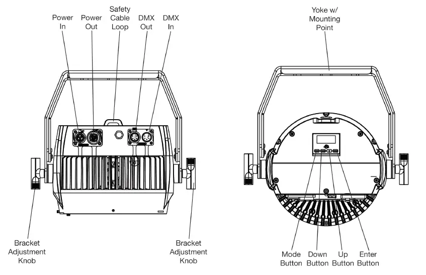
Note: DMX In/Out ports feature 5-pin connections for the US market, and 3-pin connections for the EU market.
INSTALLATION
FLAMMABLE MATERIAL WARNING
Keep fixture minimum 5.0 feet (1.5m) away from flammable materials and/or pyrotech-nics.
ELECTRICAL CONNECTIONS
A qualified electrician should be used for all electrical connections and/or installations. USE CAUTION WHEN POWER LINKING FIXTURES OF OTHER MODEL TYPES, AS THE POWER CONSUMPTION OF OTHER MODEL FIXTURES MAY EXCEED THE MAX POWER OUTPUT ON THIS FIXTURE. CHECK SILK SCREEN FOR MAX AMPS. MINIMUM DISTANCE TO OBJECTS/SURFACES IS 6.6 FEET (2 METERS). MINIMUM DISTANCE OF INFLAMMABLE MATERIALS FROM THE SURFACE IS 1.6 FEET (0.5 METER)
DO NOT INSTALL THE FIXTURE IF YOU ARE NOT QUALIFIED TO DO SO!
- Fixture MUST be installed following all local, national, and country commercial electrical and con-struction codes and regulations.
- Before rigging/mounting a single fixture or multiple fixtures to any metal truss/structure or placing the fixture(s) on any surface, a professional equipment installer MUST be consulted to determine if the metal truss/structure or surface is properly certified to safely hold the combined weight of the fixture(s), clamps, cables, and accessories.
- Maximum fixture ambient operating temperature is 113°F (45°C). Do not use operate the fixture when ambient temperature exceeds this value!
- Fixture(s) should be installed in areas outside walking paths, seating areas, or areas were unau-thorized personnel might reach the fixture by hand.
- NEVER stand directly below the fixture(s) when rigging, removing or servicing.
- Overhead fixture installation must always be secured with a secondary safety attachment, such as an appropriately rated safety cable.
- low approximately 60 minutes for the fixture to cool down before servicing.
IP RATING
This device is IP65 rated. This means that the unit is dust-tight, and protected against low-pressure jets of water from any direction.
RIGGING
Overhead rigging requires extensive experience, including calculating working load limits, installation material being used, and periodic safety inspection of all installation material and the fixture, among other skills. If you lack these qualifications, do not attempt the installation yourself. Improper installation can result in bodily injury.
INSTALLATION
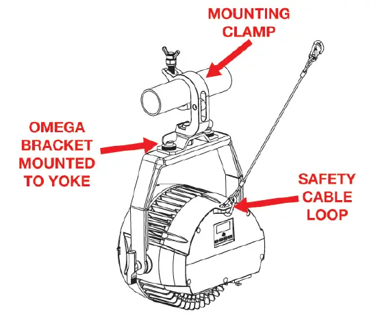
CLAMP INSTALLATION
This fixture features a mounting point on the yoke for the attachment of an Omega bracket and mounting clamp. There is also a safety cable loop located on the rear of the fixture near the display screen (see the illustration below). When mounting the fixture to a truss or any other suspended or overhead installation, be sure to secure appropriately rated clamps and Omega brackets (not includ-ed) to the yoke, and attach a separate SAFETY CABLE of the appropriate weight rating to the safety cable loop.
CONNECTIONS
Ensure all connections and end caps are properly sealed with a dielectric grease (available at most electrical suppliers) to prevent corrosion, water intrusion, and/or electrical short circuiting. In order to maintain IP65 rating integrity and prevent water from entering the fixture, all unused con-nections must be sealed by closing their protective rubber caps.
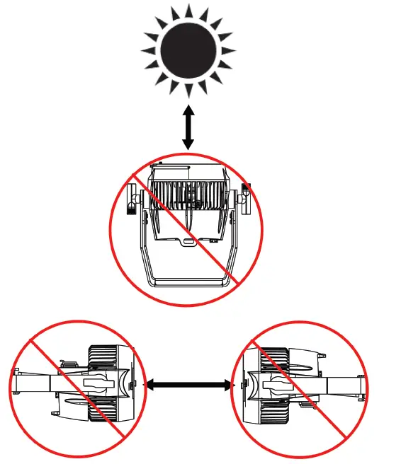
POTENTIAL INTERNAL FIXTURE DAMAGE FROM EXTERNAL SOURCES OF LIGHT BEAMS
External sources of light beams from direct sunlight, lighting moving head fixtures, and lasers which are focused directly towards the exterior housing and/or penetrate the front lens opening of ADJ lighting fixtures can cause severe internal damage including burning of optics, dichroic color filters, glass and metal gobos, prisms, animation wheels, frost filters, irises, shutters, motors, belts, wiring, discharge lamps, and LEDs. This issue is not unique to ADJ lighting fixtures; it is a common issue with lighting fixtures from all manufacturers. Although there is no true way to fully prevent this issue from happening, the guide-lines below can reduce the risk of any potential damage if followed. Contact ADJ Service for more details.
DO NOT EXPOSE THE FIXTURE AND/OR FRONT LENS OPENING TO LIGHT BEAMS FROM DIRECT SUNLIGHT, OTHER LIGHTING MOVING HEAD FIXTURES, AND LASERS DURING UNPACKING, INSTALLATION, USE, AND EXTENDED IDLE TIMES OUTDOORS. DO NOT FOCUS A LIGHT BEAM FROM ONE LIGHTING FIXTURE DIRECTLY TOWARDS ANOTHER.
REMOTE DEVICE MANAGEMENT (RDM)
NOTE: In order for RDM to work properly, RDM-enabled equipment must be used throughout the entire system, including DMX data splitters and wireless systems.
Remote Device Management (RDM) is a protocol that sits on top of the DMX512 data standard for lighting, allowing the DMX systems of the fixtures to be modified and monitored remotely. This proto-col is ideal for instances in which a unit is installed in a location that is not easily accessible. With RDM, the DMX512 system becomes bi-directional, allowing a compatible RDM-enabled controller to send out a signal to devices on the wire, as well as allowing the fixture to respond (known as a GET command). The controller can then use its SET command to modify settings that would typically have to be changed or viewed directly via the unit’s display screen, including the DMX Address, DMX Channel Mode, and Temperature Sensors. Please be aware that not all RDM devices support all RDM features, and therefore it is important to check beforehand to ensure that the equipment that you are considering includes all of the features that you require. The following parameters are accessible in RDM on this device:
| MANUFACTURER |
| MANUFACTURER ID |
| DEVICE ID |
| MODEL ID |
| DMX START ADDRESS |
| DMX PERSONALITY |
| DMX SLOTS |
| SOFTWARE VERSION |
CONTROL PANEL
The fixture includes an easy to navigate system menu control panel display where all necessary set-tings and adjustments are made. (See image below)
- MODE: Cycles through the main menu options and/or return to previous menu without making changes.
- DOWN/UP: Scroll through options in the selected menu.
- ENTER: Select highlighted option and/or confirm selection.
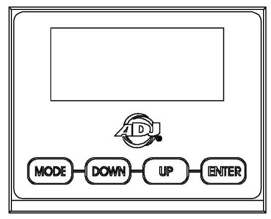
This device features two different settings for locking the keypad. Setting Lock to “ON” requires the user to simply press and hold the MODE button for 10 seconds to unlock the keypad. Setting Lock to “ON1” provides an additional safeguard against accidental unlocking by requiring a passcode to unlock the device. To unlock, press the MODE button so that “LOCKED is dis-played on the screen, then press UP DOWN UP DOWN ENTER in that particular order. Each button press will remove one asterisk from the LOCKED text on the display screen.
SYSTEM MENU
|
DMX SET | Address | 001 – 512 | Set DMX address of the unit. | |
|
Ch. Mode | 4ch | Set DMX channel mode. | ||
| 7ch | ||||
| 8ch | ||||
| 10ch | ||||
| 13ch | ||||
| 16ch | ||||
|
No DMX | Hold | Unit holds last setting if DMX signal is lost. | ||
| Blackout | Unit goes to standby mode if DMX signal is lost. | |||
| Int. Prog | Unit default to last internal program when DMX signal is lost. | |||
|
PERSONALITY | Primary | On / Off | Set primary mode. | |
| Secondary | On / Off | Set secondary mode. | ||
| Fan Set | Auto | |||
| High | ||||
| Silent | ||||
|
Dim Mode | Standard | |||
| Stage | ||||
| TV | ||||
| Archi. | ||||
| Theatre | ||||
| Stage 2 | ||||
| Dim Speed | 0.1s – 10s | |||
|
Dim Curve | Square | |||
| Linear | ||||
| Inv. Squa | ||||
| S. Curve | ||||
| LED Rfrsh | 900, 1000, 1100, 1200, 1300, 1400, 1500, 2500, 4000, 5000, 10k, 15k, 20k, 25k | Set LED refresh rate. | ||
|
Display | SaveDelay | 1 – 10 | ||
|
Lock | ON | Press and hold MODE for 10s to unlock | ||
| ON1 | Press MODE and display shows LOCKED *****. To unlock, press UP DOWN UP DOWN ENTER | |||
| OFF | Keypad in unlocked | |||
| CONTINUED ON NEXT PAGE | ||||
|
PERSONALITY (continued) |
Service |
Passcode = 050 |
Calibrat | Red 000 – 255 | |
| Green 000 – 255 | |||||
| Blue 000 – 255 | |||||
| Lime 000 – 255 | |||||
| S. Update | Yes / No | ||||
| Restore: Pass- code = 011 | Yes / No | Restore the unit to factory settings. | |||
|
MANUAL | Red | 000 – 255 | Manually adjust red | ||
| Blue | 000 – 255 | Manually adjust blue | |||
| Green | 000 – 255 | Manually adjust green | |||
| Lime | 000 – 255 | Manually adjust lime | |||
| ClrMacro | 00 – 64 | Select color macro | |||
| ClrTemp | 000 – 255 | Set color temperature | |||
| ClrTeMac | 000 – 255 | Select color temp. macro | |||
| Strobe | 000 – 255 | Manually adjust strobe | |||
| MastrDim | 000 – 255 | Manually set master dimmer | |||
| AutoProg | 000 – 255 | Select auto program | |||
| ProgSpd | 000 – 255 | Set program speed | |||
| ProgFade | 000 – 255 | Set program fade | |||
|
INTPROGS | Prog 0 | Speed | 000 – 255 | ||
| Fade | 000 – 255 | ||||
| Prog 1 | Speed | 000 – 255 | |||
| Fade | 000 – 255 | ||||
| … | … | … | |||
| Prog 7 | Speed | 000 – 255 | |||
| Fade | 000 – 255 | ||||
|
INFO |
Hours | PwrOnHr1 | xxx Hrs | Total hours that fixture has been powered on. Non- resettable. | |
| PwrOnHr2 | xxx Hrs | Hours that fixture has been powered on since last reset. | |||
| PwrOnRst | Passcode = 050 | Reset hours to zero. | |||
|
Temp. | xxx° | xxx F / xxx C | |||
| MaxTemp1 | xxx F / xxx C | Max temp since last reset. | |||
| MaxTemp2 | xxx F / xxx C | All time max temp, non- resettable. | |||
| TempRst. | Yes / No | Passcode = 050 | Reset LED temp. | ||
|
CONTINUED ON NEXT PAGE | |||||
|
INFO (contin- ued) |
DMX Values | Red |
Displays current DMX values for each DMX channel. |
| Green | |||
| … | |||
| AutoProg | |||
| SoftVers | x.xx | Displays current software version. |
DMX SETUP
DMX-512: DMX is short for Digital Multiplex. This is a universal protocol used as a form of commu-nication between intelligent fixtures and controllers. A DMX controller sends DMX data instructions from the controller to the fixture. DMX data is sent as serial data that travels from fixture to fixture via the DATA “IN” and DATA “OUT” XLR terminals located on all DMX fixtures (most controllers only have a DATA “OUT” terminal).
DMX Linking: DMX is a language allowing all makes and models of different manufacturers to be linked together and operate from a single controller, as long as all fixtures and the controller are DMX compliant. To ensure proper DMX data transmission, try to use the shortest cable path possible when using several DMX fixtures. The order in which fixtures are connected in a DMX line does not influence the DMX addressing. For example, a fixture assigned a DMX address of 1 may be placed anywhere in a DMX line: at the beginning, at the end, or anywhere in the middle. When a fixture is assigned a DMX address of 1, the DMX controller knows to send DATA assigned to address 1 to that unit, no matter where it is located in the DMX chain.
Data Cable (DMX Cable) Requirements (For DMX Operation):The Encore LP18IP can be con-trolled via DMX-512 protocol, and features multiple DMX channel modes. Your unit and your DMX controller require either a 3-pin (for EU markets) or 5-pin (for US markets) XLR connector for data input and data output. If you are making your own cables, be sure to use standard 110-120 Ohm shielded cable (This cable may be purchased at almost all pro lighting stores). Your cables should be made with a male XLR connector at one end and a female XLR connector on the other. Also remem-ber that DMX cable must be daisy chained and cannot be split.
Special Note: Line Termination. When longer runs of cable are used, you may need to use a ter-minator on the last unit to avoid erratic behavior. A terminator is a 110-120 ohm 1/4 watt resistor which is connected between pins 2 and 3 of a male XLR connector (DATA + and DATA -). This unit is inserted in the female XLR connector of the last unit in your daisy chain to terminate the line. Using a cable terminator (ADJ part number Z-DMX/T) will decrease the chances of erratic behavior.
5-Pin XLR DMX Connectors Some manufacturers use 5-pin XLR connectors for DATA transmis-sion in place of 3-pin. 5-pin XLR fixtures may be implemented in a 3-pin XLR DMX line. When insert-ing standard 5-pin XLR connectors in to a 3-pin line, a cable adaptor must be used. These adaptors are readily available at most electric stores. The chart below details a proper cable conversion:
| Channel Mode | Unit 1 Address | Unit 2 Address | Unit 3 Address | Unit 4 Address |
| 4 Channels | 1 | 5 | 9 | 13 |
| 7 Channels | 1 | 8 | 15 | 22 |
| 8 Channels | 1 | 9 | 17 | 25 |
| 10 Channels | 1 | 11 | 21 | 31 |
| 13 Channels | 1 | 14 | 27 | 40 |
| 16 Channels | 1 | 17 | 33 | 49 |
DMX TRAITS
| CHANNEL | DMX VALUE | FUNCTION | |||||
| 4CH | 7CH | 8CH | 10CH | 13CH | 16CH | ||
| 1 | 1 | 1 | 1 | 1 | 1 | 000 – 255 | Red, 0% – 100% |
| 2 | 000 – 255 | Red Fine | |||||
| 2 | 2 | 3 | 2 | 2 | 2 | 000 – 255 | Green, 0% – 100% |
| 4 | 000 – 255 | Green Fine | |||||
| 3 | 3 | 5 | 3 | 3 | 3 | 000 – 255 | Blue, 0% – 100% |
| 6 | 000 – 255 | Blue Fine | |||||
| 4 | 4 | 7 | 4 | 4 | 4 | 000 – 255 | Lime, 0% – 100% |
| 8 | 000 – 255 | Lime Fine | |||||
| 5 | 5 | 5 | 000 – 255 | Color Macros, see Color Macros Chart section for de- tailed information | |||
| 6 | 6 | 6 | 000 – 255 | Color Temperature, 2700K – 7000K Linear | |||
|
7 |
7 |
7 | Color Temperature Macros | ||||
| 000 | Off | ||||||
| 001 – 054 | 2700K | ||||||
| 055 – 109 | 3200K | ||||||
| 110 – 164 | 4000K | ||||||
| 165 – 219 | 5600K | ||||||
| 220 – 255 | 6500K | ||||||
|
5 |
8 |
8 |
8 | Shutter, Strobe | |||
| 000 – 031 | LEDs Off | ||||||
| 032 – 063 | LEDs On | ||||||
| 064 – 095 | Strobe effect, slow to fast | ||||||
| 096 – 127 | LEDs On | ||||||
| 128 – 159 | Pulse-effect in sequences | ||||||
| 160 – 191 | LEDs On | ||||||
| 192 – 223 | Random strobe effect, slow to fast | ||||||
| 224 – 255 | LEDs On | ||||||
| 6 | 9 | 9 | 9 | 000 – 255 | Dimmer Intensity, 0% – 100% | ||
| 7 | 10 | 10 | 10 | 000 – 255 | Dimmer Fine | ||
|
11 | Auto Programs | ||||||
| 000 – 031 | Off | ||||||
| 032 – 063 | Auto Program 1 | ||||||
| 064 – 095 | Auto Program 2 | ||||||
| 096 – 127 | Auto Program 3 | ||||||
| 128 – 159 | Auto Program 4 | ||||||
| CONTINUED ON NEXT PAGE | |||||||
| CHANNEL | DMX VALUE | FUNCTION | |||||
| 4CH | 7CH | 8CH | 10CH | 13CH | 16CH | ||
|
11 | Auto Programs (continued) | ||||||
| 160 – 191 | Auto Program 5 | ||||||
| 192 – 223 | Auto Program 6 | ||||||
| 224 – 255 | Auto Program 7 | ||||||
| 12 | 000 – 255 | Auto Program Speed, slow to fast | |||||
| 13 | 000 – 255 | Auto Program Fade, least to most | |||||
|
11 |
14 | Dim Mode | |||||
| 000 – 020 | Default to unit setting | ||||||
| 021 – 040 | Standard | ||||||
| 041 – 060 | Stage | ||||||
| 061 – 080 | TV | ||||||
| 081 – 100 | Architectural | ||||||
| 101 – 120 | Theatre | ||||||
| 121 – 140 | Stage 2 | ||||||
| 141 | 0.1s dim speed | ||||||
| 142 | 0.2s dim speed | ||||||
| 143 | 0.3s dim speed | ||||||
| 144 | 0.4s dim speed | ||||||
| 145 | 0.5s dim speed | ||||||
| 146 | 0.6s dim speed | ||||||
| 147 | 0.7s dim speed | ||||||
| 148 | 0.8s dim speed | ||||||
| 149 | 0.9s dim speed | ||||||
| 150 | 1.0s dim speed | ||||||
| 151 | 1.5s dim speed | ||||||
| 152 | 2.0s dim speed | ||||||
| 153 | 3.0s dim speed | ||||||
| 154 | 4.0s dim speed | ||||||
| 155 | 5.0s dim speed | ||||||
| 156 | 6.0s dim speed | ||||||
| 157 | 7.0s dim speed | ||||||
| 158 | 8.0s dim speed | ||||||
| 159 | 9.0s dim speed | ||||||
| 160 | 10.0s dim speed | ||||||
| 161 – 255 | Default to unit setting | ||||||
| CONTINUED ON NEXT PAGE | |||||||
| CHANNEL | DMX VALUE | FUNCTION | |||||
| 4CH | 7CH | 8CH | 10CH | 13CH | 16CH | ||
|
12 |
15 | Dim Curves | |||||
| 000 – 020 | Square | ||||||
| 021 – 040 | Linear | ||||||
| 041 – 060 | Inv. Squa | ||||||
| 061 – 080 | S. Curve | ||||||
| 081 – 255 | No function | ||||||
|
13 |
16 | Refresh Rate | |||||
| 000 – 015 | Default to Unit Setting | ||||||
| 016 – 030 | 900 Hz | ||||||
| 031 – 045 | 1000 Hz | ||||||
| 046 – 060 | 1100 Hz | ||||||
| 061 – 075 | 1200 Hz | ||||||
| 076 – 090 | 1300 Hz | ||||||
| 091 – 105 | 1400 Hz | ||||||
| 106 – 120 | 1500 Hz | ||||||
| 121 – 135 | 2500 Hz | ||||||
| 136 – 150 | 4000 Hz | ||||||
| 151 – 165 | 5000 Hz | ||||||
| 166 – 180 | 10000 Hz | ||||||
| 181 – 195 | 15000 Hz | ||||||
| 196 – 210 | 20000 Hz | ||||||
| 211 – 225 | 25000 Hz | ||||||
| 226 – 255 | No Function | ||||||
COLOR MACROS CHART
| COLOR MACRO NO. | DMX VALUE | RED | GREEN | BLUE | LIME |
| Off | 000 | 0 | 0 | 0 | 0 |
| 1 | 001 – 004 | 80 | 255 | 234 | 80 |
| 2 | 005 – 008 | 80 | 255 | 164 | 80 |
| 3 | 009 – 012 | 77 | 255 | 112 | 77 |
| 4 | 013 – 016 | 117 | 255 | 83 | 83 |
| 5 | 017 – 020 | 160 | 255 | 77 | 77 |
| 6 | 021 – 024 | 223 | 255 | 83 | 83 |
| 7 | 025 – 028 | 255 | 243 | 77 | 77 |
| 8 | 029 – 032 | 255 | 200 | 74 | 74 |
| 9 | 033 – 036 | 255 | 166 | 77 | 77 |
| 10 | 037 – 040 | 255 | 125 | 74 | 74 |
| 11 | 041 – 044 | 255 | 97 | 77 | 71 |
| 12 | 045 – 048 | 255 | 71 | 77 | 71 |
| 13 | 049 – 052 | 255 | 83 | 134 | 83 |
| 14 | 053 – 056 | 255 | 93 | 182 | 93 |
| 15 | 057 – 060 | 255 | 96 | 236 | 96 |
| 16 | 061 – 064 | 238 | 93 | 255 | 93 |
| 17 | 065 – 068 | 196 | 87 | 255 | 87 |
| 18 | 069 – 072 | 150 | 90 | 255 | 90 |
| 19 | 073 – 076 | 100 | 77 | 255 | 77 |
| 20 | 077 – 080 | 77 | 100 | 255 | 77 |
| 21 | 081 – 084 | 67 | 148 | 255 | 67 |
| 22 | 085 – 088 | 77 | 195 | 255 | 77 |
| 23 | 089 – 092 | 77 | 234 | 255 | 77 |
| 24 | 093 – 096 | 158 | 255 | 144 | 144 |
| 25 | 097 – 100 | 255 | 251 | 153 | 153 |
| 26 | 101 – 104 | 255 | 175 | 147 | 147 |
| 27 | 105 – 108 | 255 | 138 | 186 | 138 |
| 28 | 109 – 112 | 255 | 147 | 251 | 147 |
| 29 | 113 – 116 | 151 | 138 | 255 | 138 |
| 30 | 117 – 120 | 99 | 0 | 255 | 100 |
| 31 | 121 – 124 | 138 | 169 | 255 | 138 |
| 32 | 125 – 128 | 255 | 255 | 255 | 255 |
| 33 | 129 – 132 | 255 | 206 | 143 | 0 |
| 34 | 133 – 136 | 254 | 177 | 153 | 0 |
| 35 | 137 – 140 | 254 | 192 | 138 | 0 |
| 36 | 141 – 144 | 254 | 165 | 98 | 0 |
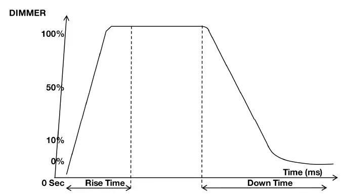
DIM MODES
CLEANING AND MAINTENANCE
DISCONNECT POWER BEFORE PERFORMING ANY MAINTENANCE!
CLEANING
Frequent cleaning is recommended to ensure proper function, optimized light output, and an extended life. The frequency of cleaning depends on the environment in which the fixture oper-ates: damp, smoky, or particularly dirty environments can cause greater accumulation of dirt on the fixture’s optics. Clean the external lens surface periodically with a soft cloth to avoid dirt/debris accumulation. NEVER use alcohol, solvents, or ammonia-based cleaners.
MAINTENANCE
Regular inspections are recommended to ensure proper function and extended life. There are no user serviceable parts inside this fixture. Please refer all other service issues to an authorized ADJ service technician. Should you need any spare parts, please order genuine parts from your local ADJ dealer. Please refer to the following points during routine inspections:
- A detailed electrical check by an approved electrical engineer every three months, to make sure the circuit contacts are in good condition and prevent overheating.
- Be sure all screws and fasteners are securely tightened at all times. Loose screws may fall out during normal operation, resulting in damage or injury as larger parts could fall.
- Check for any deformations on the housing, color lenses, rigging hardware, and rigging points
(ceiling, suspension, trussing). Deformations in the housing could allow for dust or liquids to enter into the fixture. Damaged rigging points or unsecured rigging could cause the fixture to fall and seriously injure a person(s). - Electric power supply cables must not show any damage, material fatigue, or sediments.
- NEVER remove the ground prong from the power cable.
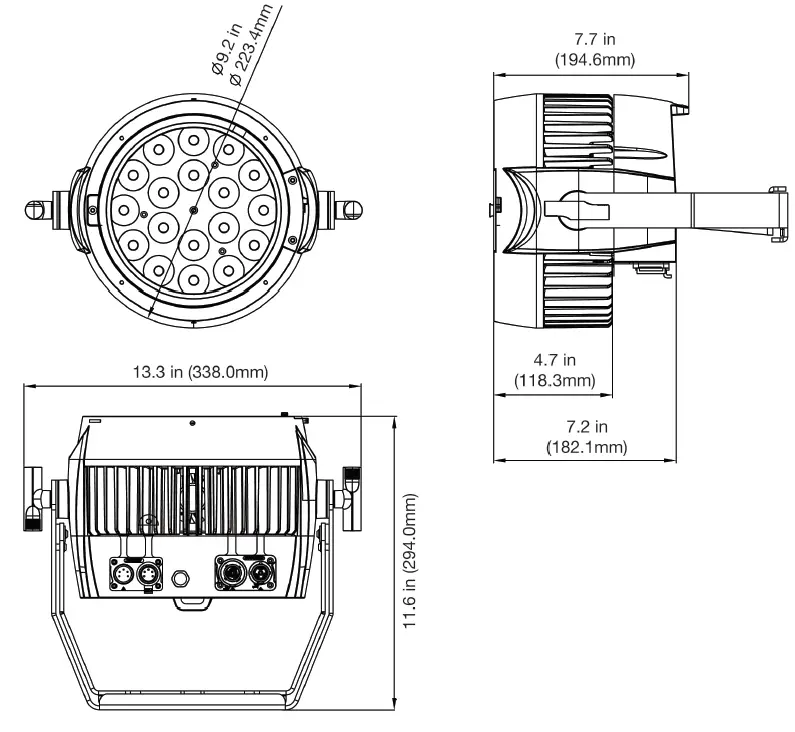
DIMENSIONAL DRAWINGS
SPECIFICATIONS
SOURCE:
Light Source: 18 x 20-Watt Quad RGBL LEDs (4-IN-1: Red, Green, Blue & Lime)
PHOTMETRIC DATA:
- Beam angle: 10-degree
- CRI: 86.2
- CRI R9: 82.8
- Lumens: 7300
EFFECTS:
- Linear Color Temperature Control (2700K to 7000K)
- Preset Color Temperatures (2700K, 3200K, 4000K, 5600K and 6500K)
- 16-Bit Fine Color Control (Red, Green, Blue & Lime)
- 64 built-in Color Macros
CONTROL / CONNECTIONS:
- 4-button, DMX digital display on rear panel
- DMX In/Out Connections (3-pin in EU / 5-pin in US)
- 5 Operational modes: Static Color Mode, RGBL Dimmer Mode, Program Mode, and DMX Controlled
- Supports RDM (Remote Device Management)
- With Wired Digital Communication Network
- 6 selectable Dimming Modes (Standard, Stage, TV, Architectural, Theatre & Stage 2)
- 4 selectable Dim Curves (Linear, Square Inv. Squa, S-Curve)
- Adjustable Refresh Rate (14 presets from 900 – 25,000Hz)
- Flicker Free operation (No flickering on camera)
- LED pulse and strobe effect
- Electronic Dimming: 0 – 100%
- 6 DMX Modes: 4, 7, 8, 10, 13, & 16-channel
- Quiet fan mode
CONSTRUCTION:
- IP65 Rated: Ingress Protection against liquid, snow, dust and sand
- All metal construction
- IP Rated rubber covers protect In/Out Locking Power connectors and IP rated 5-pin sockets
- Locking, outdoor IN/Out Power connectors
- Data linkable via 3-pin or 5-pin DMX connections (3-pin in EU / 5-pin in US)
- Includes Lens kit with 4 different beam angles
- Scissor Yoke & safety eye
ELECTRICAL / THERMAL:
- Multi-voltage operation: AC 100-240V, 47/63Hz
- Daisy chain: 2 @ 120V, 6 @ 220V
- Max power: 240W
DIMENSIONS / WEIGHT:
- Dimensions (LxWxH): 11.6” x 9.2” x 13.3” / 294.0mm x 223.4mm x 338.0mm
- Weight: 16 lbs. / 7.15 kg.
APPROVALS / RATINGS:
- cETLus Pending
- IP65


