LAPETEK 57010 Kitchen Ventilators
These maintenance instructions applies to the following products
| PRODUCT | CODE | VERSIONS |
| APOLLO-V S/S | 57010 | 001 |
| APOLLO-V VALKOINEN / WHITE / VIT | 57011 | 001 |
| APOLLO-V BLACK | 57012 | 001 |
| JONA SLIM 60 RST/S/S/RF | 57001 | 001 |
| JONA SLIM 60 WHITE | 57002 | 001 |
| JONA SLIM 60 MUSTA /BLACK/ SVART | 57003 | 001 |
| JONA SLIM 90 S/S | 57004 | 001 |
| JONA SLIM 90 WHITE | 57005 | 001 |
| JONA SLIM 90 BLACK | 57006 | 001 |
| JONA SLIM-V 90 S/S | 57007 | 001 |
| JONA SLIM-V 90 WHITE | 57008 | 001 |
| JONA SLIM-V 90 BLACK | 57009 | 001 |
| FREE 54 S/S | 57014 | 001 |
| TEXALINE 60 S/S | 57030 | 001 |
| TEXALINE 60 VALKOINEN/WHITE/VIT | 57031 | 001 |
| TEXALINE 60 BLACK | 57032 | 001 |
| TEXALINE S/S | 57033 | 001 |
| TEXALINE 90 WHITE | 57034 | 001 |
| TEXALINE 90 MUSTA BLACK | 57035 | 001 |
| TREKK 50 WHITE | 57040 | 001 |
| TREKK 50 BLACK | 57042 | 001 |
| TREKK 60 WHITE | 001 | |
| TREKK 60 BLACK | 57045 | 001 |
APOLLO-V: REPLACEMENT OF LIGHTING
- Before replacing the lamp, open the hatch.

- Remove the screws of the back cover and then the back cover

- Disconnect the quick connector of the lamp. Replace the lamp and reassemble in reverse order
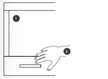
JONA SLIM &JONA SLIM-V: REPLACEMENT OF LIGHTING
- Remove the grease filters before replacing the lamp.
- Push the lamp gently inwards to release it from the body of the hood

- Gently push the lamp inside the hood in the direction of the arrow pressing from outside at the same time to release it from the holders inside the hood.
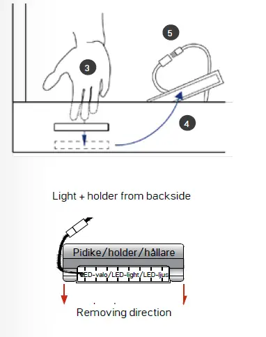
- Carefully pull out the lamp.
- Disconnect the cable (quick connector 5) and replace the lamp.

- Install a new lamp in reverse order

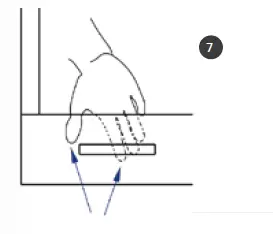
- Finally, squeeze the lamp and its holder in place inside the hood to securely attach the lamp to the body of the hood.

FREE 54: REPLACEMENT OF LIGHTING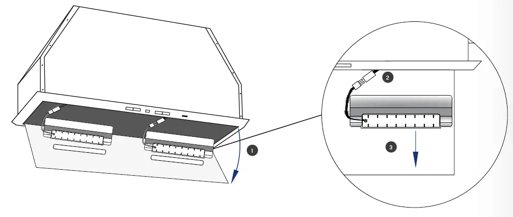
- Before replacing the lamp, open the lamp hatch
- Disconnect the quick connector of the light fixture
- Pull the lamp out of its holder. Replace the lamp and reassemble in reverse order.
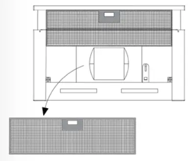
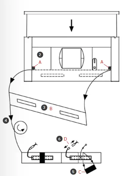
TREKK 50/60: REPLACEMENT OF LIGHTING
- Remove the grease filters before replacing the lamp

- Remove the light panel screws A) on both sides
- Remove the light panel B) from the cooker hood
- Turn the light panel over
- Remove the light holder C)
- Disconnect the light connectors D) and replace the lamp

- Assemble in reverse order
INSTALLING THE CHARCOAL FILTERS
- Single-use charcoal filters must be replaced at 3-4 times a year. However, the frequency in which the filters need to be replaced depends on usage.
- The machine-washable LongLife charcoal filters (accessory) are cleaned and activated by washing them in the dishwasher in 65 degrees. Please note that no other dishes are to be washed at the same time as the charcoal filter. Afterwards the filters are placed in a 100-degree oven on the grid for 10 minutes with upper and lower heat set. Cleaning and activating the filters should be done approximately every two months. After three years, the efficiency of the LongLife filters will be reduced by approximately 50% of the original
JONA SLIM-V 90, FREE 54 & TEXALINE 60 /90
- Installing the single-use charcoal filters

- Installing the LongLife charcoal filters

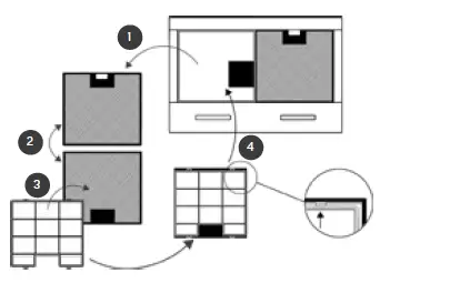

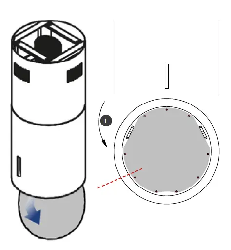
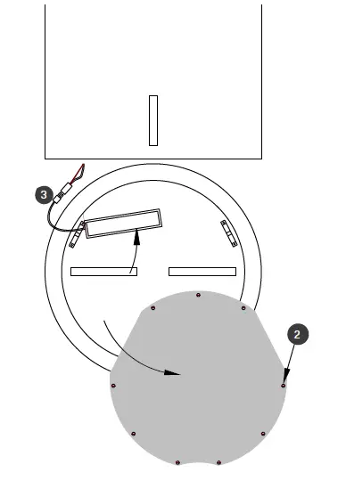
TREKK 50/60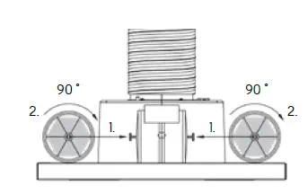
Installing the single-use charcoal filters
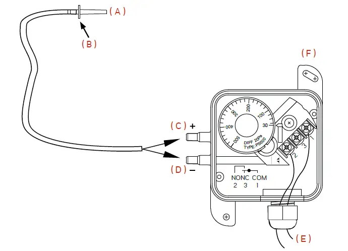
INSTALLATION OF THE DIFFERENTIAL PRESSURE SWITCH
- Drill a 6,50 mm hole in the flue for the sensor (A) and push the tip of the sensor all the way to the flange (B). The flange is attached either with silicone or with screws. The tip of the sensor can easily be cut to a desired length.
- When connecting to a cooker hood with own motor, connect the sensor tube to the (+) connection (C).
- When using a hood with a roof fan, connect the sensor tube to the (-) connection (D).
- The control unit (F) is mounted on the wall as shown in the picture.
- Airpressure data to the air-conditioning device (E).
When using a cooker hood with own motor, install the sensor of the differential pressure switch between the cooker hood and the non-return valve.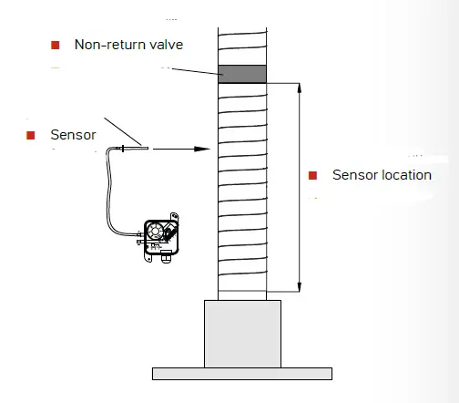
When using a hood with a roof fan in X1 mode, install the differential pressure switch in the flue over the non-return valve. In X2 and X3 modes, the differential pressure switch is installed between the roof fan and the air-conditioning device.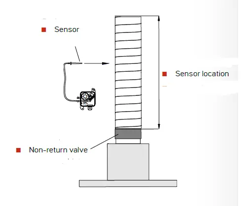
CONTACT
Oy Lapetek Ab
www.lapetek.fi
Sales, Technical support and service
[email protected]
The manufacturer declines all responsibility in the event of any printing mistakes in this booklet. The manufacturer also reserves the right to make appropriate modifications to its products without changing the essential characteristics


