BLAUPUNKT THA 260 2-4 Channel Amplifier Instruction Manual
System Planning
Proper system planning is the best way to maximize your amplier’s performance. By planning your installation carefully, you can avoid situations where the performance and reliability of your system is compromised. Our authorized dealer has been trained to maximize your system’s sound quality when installing the amplier, and is a valuable resource in helping you with your system’s design and installation.
Speaker Requirements
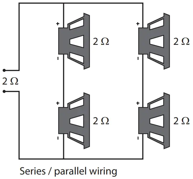
Each channel of your amplier can easily handle 2W n speaker loads when used in Stereo Mode. When a channel-pair is bridged, the recommended minimum load impedance is 4W for subwoofer use or full range operation. Although operation with lower impedances is not likely to cause immediate damage to the internal circuitry, the unit will most likely overheat, causing the thermal protection circuitry to shut down the amplier. When the chassis cools down, normal operation will resume.
Continuing to operate the amplier under these conditions is not recommended and will reduce its life expectancy. Most speakers designed for car audio operation are 4W impedance. Connecting two such speakers in parallel will result in a 2W nominal impedance, which is not recommended for use with bridged channels of your amplier.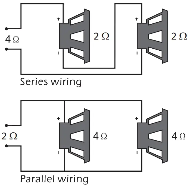
Symptom | Possible Cause | Action to take |
| Poor bass response | Speakers wired wrong polarity causing cancellation at low frequencies | Check speaker polarity & change as needed |
| Crossover set incorrectly | Reset crossover referring to the multi-cross crossover configuration section of this manual for detailed instructions | |
| Battery fuse blowing | Impedance load to amplifier too low | Check speaker impedance load. If below 20 stereo or 40 mono, rewire speakers to achieve a higher impedance |
| Short in power wire or incorrect power connections | Check power and ground connections and repair as needed | |
| Fuse used is lower than recommended rating | Replace with proper fuse rating | |
| Too much current being drawn | Check speaker impedance load. If below 20 stereo or 40 mono, rewire speakers to achieve a higher impedance and replace with recommended fuse size | |
| Short in power wire or incorrect wire | Check power and ground connection and repair as needed | |
| Amplifier fuse blowing | Too much current being drawn | Check speaker impedance load. If below 2 0 stereo or 40 mono, rewire speakers to achieve a higher impedance and replace with recommended fuse size |
| Check power and ground connections. Repair as needed | ||
| Fuse used is lower than recommended rating | Replace with proper fuse rating |
Trouble Shooting
Symptom | Possible Cause | Action to take |
| No output | Low or no remote turn-on input | Check remote turn-on voltage output on amplifier and correct as needed |
| Fuse blown | Check power wire integrity and reverse polarity, repair as needed and replace fuse | |
| Power wires not connected Check power wire connections and repair/replace as needed | Audio input not connected or Check input connections and signal no output from source integrity repair/replace as needed
| |
| Speaker wires not connected | Check speaker wires and repair/ replace as needed | |
| Audio cycles on and off | Speakers are blown | Check system with known working speaker and repair/replace speakers as needed |
| Thermal protection engages when amplifier heat sink temperature exceeds 80°C | Make sure there is proper ventilation for amplifier and improve ventilation as needed | |
| Loose or poor audio input | Check input connections and repair/replace as needed | |
| Distorted output | Amplifier level sensitivity set too high, exceeding maximum output capability of amplifier | Reset gain. Refer to the turning section of the manual for detailed instructions |
| Impedance load to amplifier too low | Check speaker impedance load. If below 20 stereo or 40 mono, rewire speakers to achieve a higher impedance | |
| Shorted speaker wires | Check speaker wire connections and repair/replace as needed Check speaker wiring and repair/replace as needed. | |
| Speaker incorrectly connected to amplifier | Refer to the installation section of this manual for detailed instructions | |
| Speakers are blown | Check system with known working speaker and repair/replace as needed |
Connection Diagram
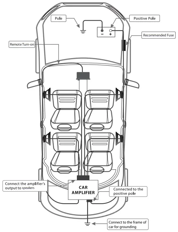
![]() Warning
Warning
Before beginning, DO NOT connect the battery’s negative poles to the positive poles. The short-circuity might cause damage to your amplifier and other electrical parts in car.
Power Connection Leads
This amplier is equipped with DC OFFSET capability when Hi input is used.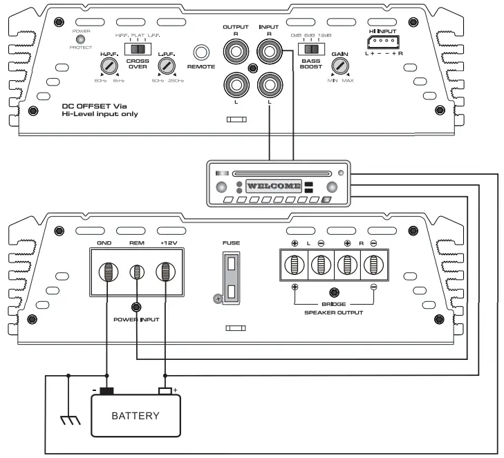
System 2: Bridge Connection Subwoofer
Specification
THA 485
- RMS output power bridged 4W(Watts): 240W x 2 CH
- RMS output power 2W(Watts): 120W x 4 CH
- RMS output power 4W(Watts): 85W x 4 CH
- THD: <0.05%
- Frequency response (±2dB): 10Hz – 30KHz
- Signal to noise ratio: >90dB
- Sensitivity: 250mV-8V
- Recommended fuse type: 35A x 2
- Dimensions: 340x190x 55 mm
System 1: 4-Channel Mode
This amplier is equipped with DC OFFSET capability when Hi input is used.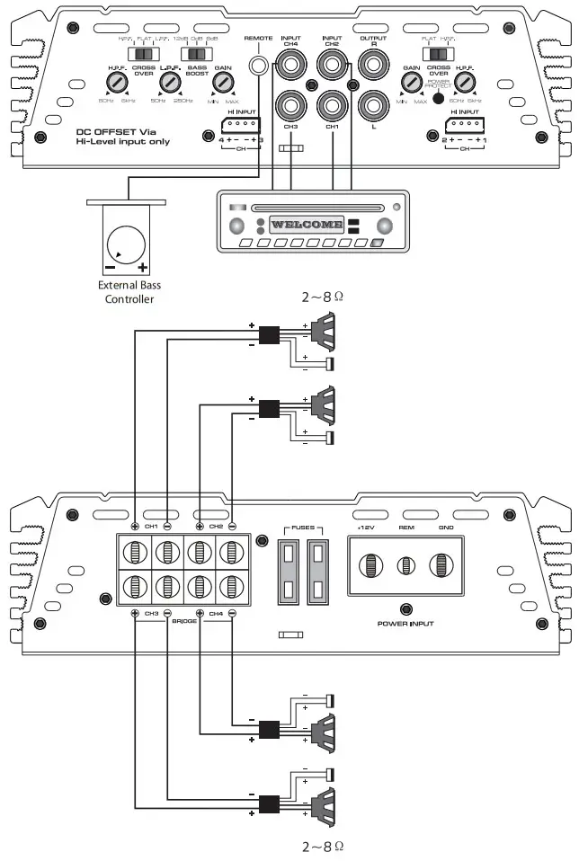
This amplier is equipped with DC OFFSET capability when Hi input is used.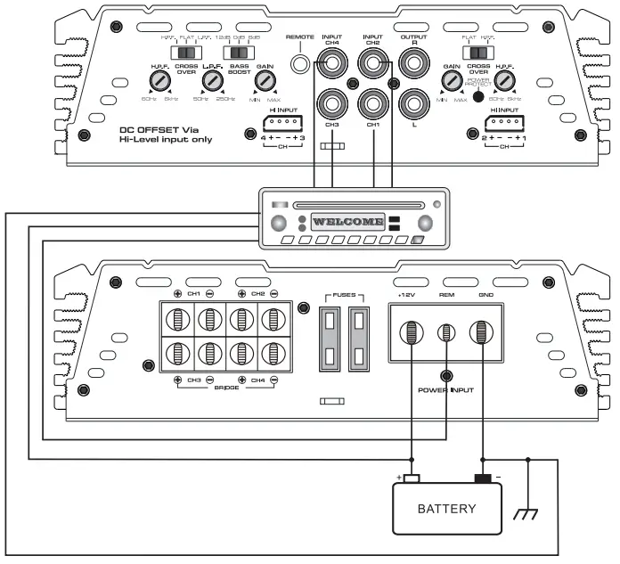
BATTERY
- Notes on the power supply Connect the + 12V power Input lead only after all other leads have been connected.
- Be sure to connect the ground wire of the unit securely to a metal part of the car.
- A loose connection may cause a malfunction of the amplier.
- REMOTE: The unit is turned on by applying + 12Volts to this terminal This terminal dose not draw heavy current like the two power terminal so a thinner connecting wire is acceptable. Standard 18 GAUGE is ne and the standard colour is blue. If the radio is equipped with a power antenna control wire, it can drive this terminal. If the power antenna wire is already in use, you can still splice into it. With this method, the unit will turn on automatically with the radio.
- Use the power supply lead with a fuse attached whose value is the same as original fuse.
- Place the fuse in the power supply lead as close as possible to the car battery.
- During a full power operation, Maximum current will run through the system.
- Therefore, Make sure the that the leads to be connected to the + 12v and GND terminals of the unit respectively must be larger than 10-Gauge (AWG. 10).
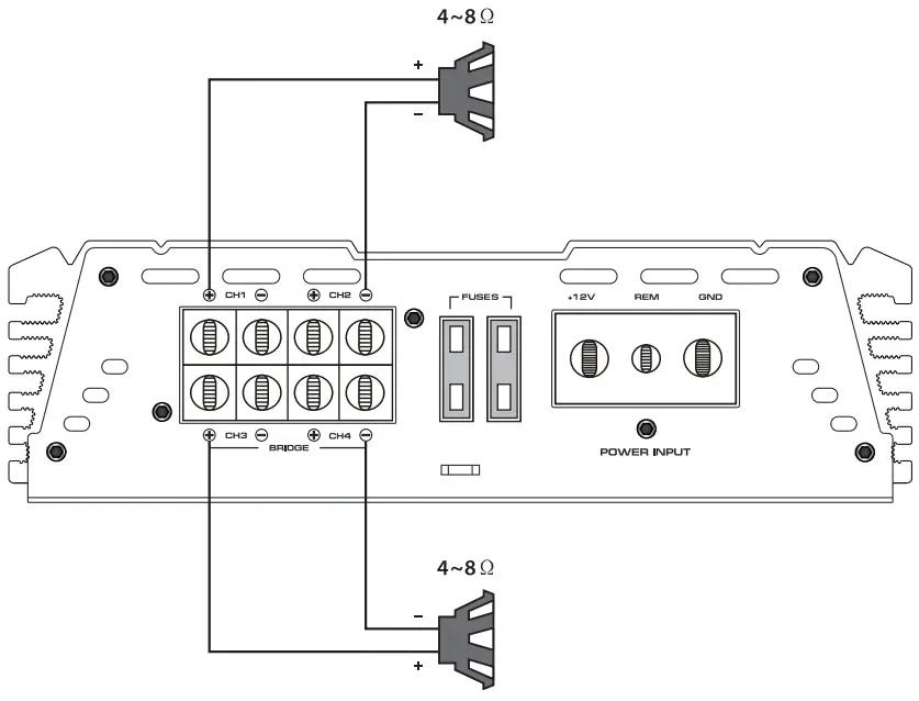
System 1: 2-Channel Mode
This amplier is equipped with DC OFFSET capability when Hi input is used.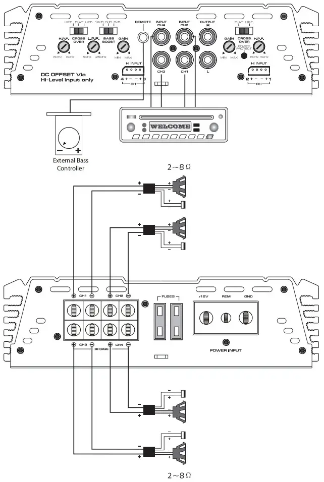
System 1: 2-Channel Mode System Subwoofer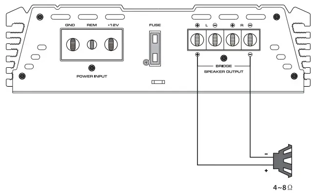
Specification:
THA 260
- RMS output power bridged 4W(Watts): 180W x 1 CH
- RMS output power 2W(Watts): 90W x 2 CH
- RMS output power 4W(Watts): 60Wx 2CH
- THD: <0.05%
- Frequency response (±2dB): 10Hz -30KHz
- Signal to noise ratio: >90dB
- Sensitivity: 250mV-8V
- Recommended fuse type: 30A x 1
- Dimensions: 220x190x55mm
Support
BPIN Private Limited
47, Atlanta Society, Nariman Point, Mumbai ‐ 400 021. Maharashtra. India.
Toll Free: 1800 209 6820
[email protected]
www.blaupunktcar.in
![]()


