HIKVISION DS-PDPG12P-EG2 Wired PIR-GlassBreak Detector
Appearance
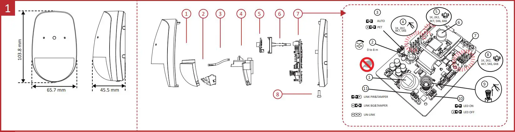
- Lens
- Pet Mask
- LED Light Pipe
- Lens Holder
- Pick Up PCBA
- Slider
- Main PCBA
- Screw
7 The Main Printed Circuit Board Assembly (PCBA)
- PIR Sensor
- BG Potentiometer
- PIR Sensitivity Settings
- Tamper Resistor Pin
- PIR Alarm Resistor Pin
- Microphone
- Terminal
- BG Alarm Resistor Pin
- Tamper Spring
- LED ON/OFF
- Link Settings

Installation
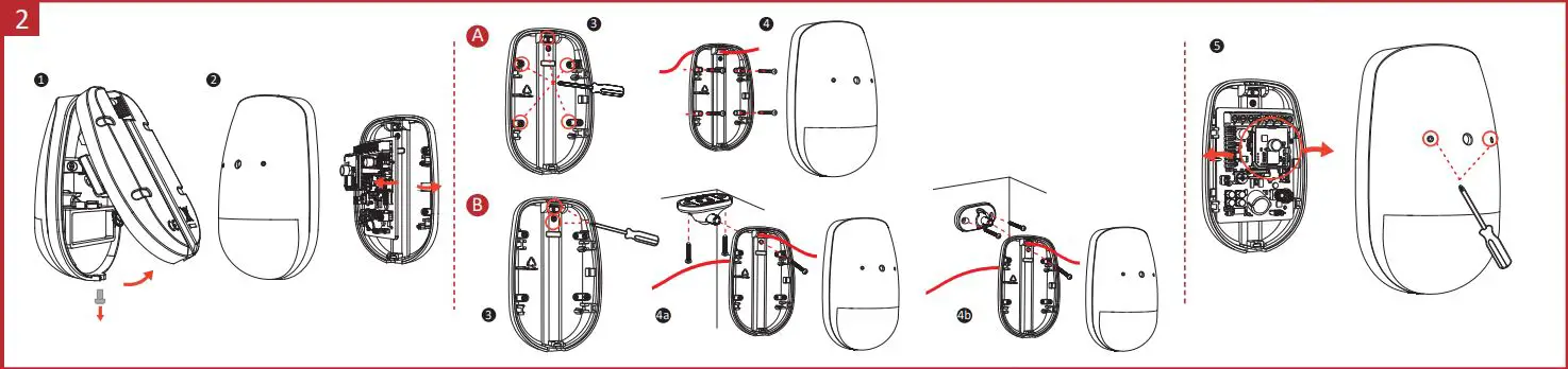
Screw Model: PA_3.5 ×25 (4 screws)
- A. Wall Mounting
- B. Bracket Mounting (optional)
- 4a. Ceiling Bracket Mounting
- 4b. Wall Bracket Mounting
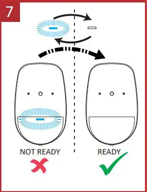
- 5. Knock out the hole, and adjusts the slider direction.
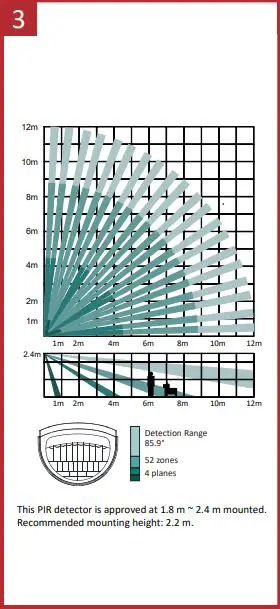
The 12 m Lens
Relay Status
| Normal | PIR Intrusion/Fault | BG Intrusion/Fault | Tamper | |
| PIR Alarm Relay | Close | Open | Close | Close |
| BG Alarm Relay | Close | Close | Open | Close |
| Tamper Relay | Close | Close | Close | Open |
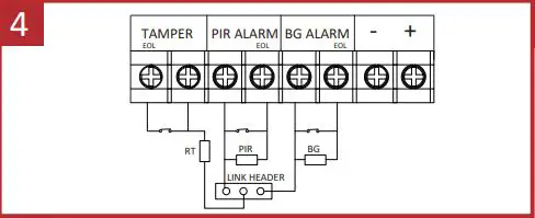
Resistor Wiring
- Method 1: Use the jumper to select EOL (End of Line) resistance on TAMPER/ALARM pins.
- Method 2: Add the resistor to TAMPER/ALARM wiring ports.
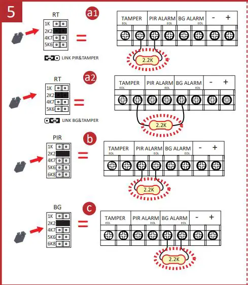
Note: If EOL wiring is not used, leave the jumpers OFF. Do not force the jumper if it is not matched the pin. Method 1 & 2 should not be used on the ALARM/TAMPER at the same time.- a. Tamper Resistance: 1K, 2K2, 4K7, 5K6
- b. PIR Alarm Resistance: 1K, 2K2, 4K7, 5K6, 6K8
- c. BG Alarm Resistance: 1K, 2K2, 4K7, 5K6, 6K8
Connection Type
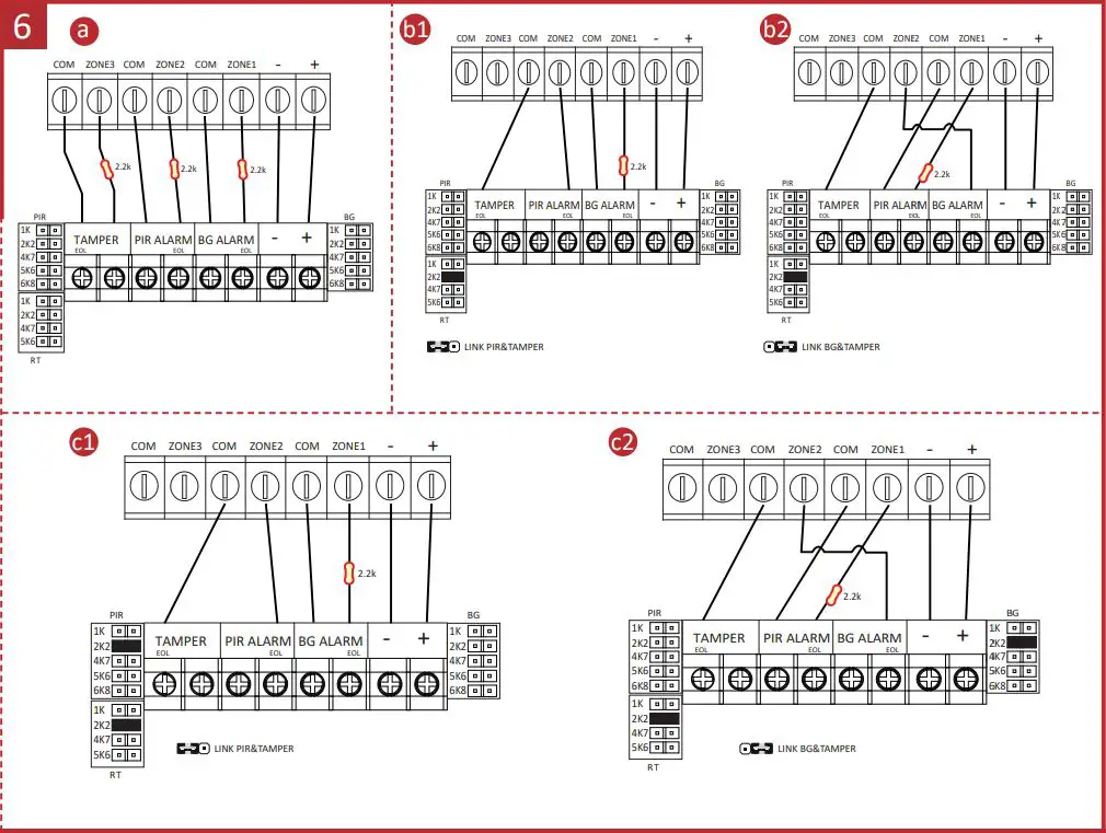
Note:
The resistor must be connected in series with one end of the detector.
- a. Normally Closed
- b. Single End of Line Wiring
- c. Double End of Line Wiring:
Powering On
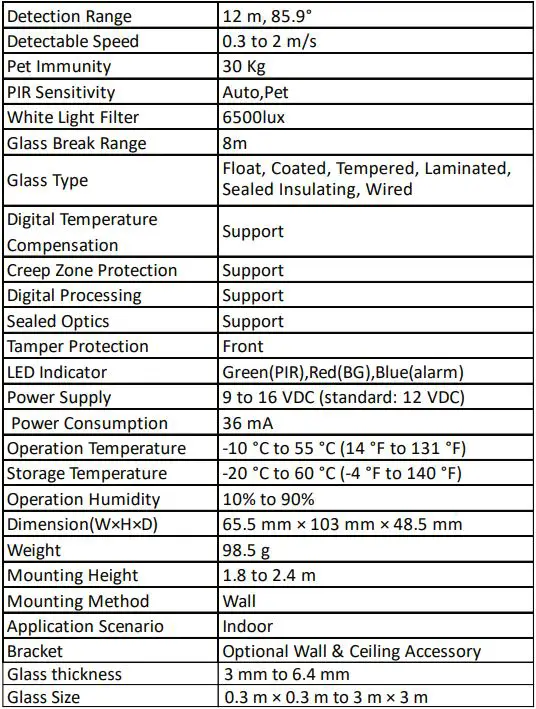
Specification
- Please use the power adapter complimenting with LPS. The recommended power adapter is made by Shenzhen Honor Electronic Co., Ltd.
- Please use the power supplies to comply with the requirements of EN 50131-6 at the appropriate grade and environmental class.
- Not to obscure partially or completely the detector’s field of view with large objects such as furniture, curtains, blinds, etc.
- Make sure that any curtains, plants, furniture, or other objects do not overcover the microphone opening.
- If there are curtains on the window, place the detector between them and the window, for instance, at the window side jamb. Otherwise, curtains can mute the glass break sound, and the detector will not be triggered.
- Before installing the detector, make sure that you have selected the optimal location that follows the guidelines of this manual:
- Avoid mounting the detector on the same wall as the protected glass.
- Avoid mounting the detector in rooms with noisy equipment (air compressors, power tools, bells, etc.)
- Avoid mounting the detector in humid rooms (bathroom, etc.)
- Avoid mounting the detector on the wall with strong vibration.


