lx nav NMEA2000 Fluid Level Converter User Manual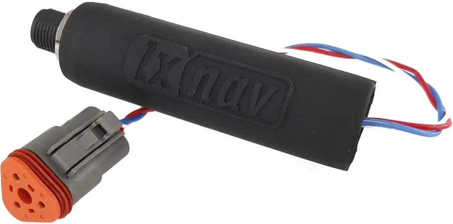
Important Notices
Information in this document is subject to change without notice. LXNAV reserves the right to change or improve their products and to make changes in the content of this material without obligation to notify any person or organization of such changes or improvements.![]()
A Yellow triangle is shown for parts of the manual which should be read very carefully and are important when operating the E500/E700.![]()
Notes with a red triangle describe procedures which are critical and may result in loss of data or any other critical situation.
A bulb icon is shown when a useful hint is provided to the reader.
Limited Warranty
This Engine Monitoring Unit product is warranted to be free from defects in materials or workmanship for two years from the date of purchase. Within this period, LXNAV will, at its sole option, repair or replace any components that fail in normal use. Such repairs or replacement will be made at no charge to the customer for parts and labour, provided that the customer pays for shipping costs. This warranty does not cover failures due to abuse, misuse, accident, or unauthorized alterations or repairs.
THE WARRANTIES AND REMEDIES CONTAINED HEREIN ARE EXCLUSIVE AND IN LIEU OF ALL OTHER WARRANTIES EXPRESSED OR IMPLIED OR STATUTORY, INCLUDING ANY LIABILITY ARISING UNDER ANY WARRANTY OF MERCHANTABILITY OR FITNESS FOR A PARTICULAR PURPOSE, STATUTORY OR OTHERWISE. THIS WARRANTY GIVES YOU SPECIFIC LEGAL RIGHTS, WHICH MAY VARY FROM STATE TO STATE.
IN NO EVENT SHALL LXNAV BE LIABLE FOR ANY INCIDENTAL, SPECIAL, INDIRECT OR CONSEQUENTIAL DAMAGES, WHETHER RESULTING FROM THE USE, MISUSE, OR INABILITY TO USE THIS PRODUCT OR FROM DEFECTS IN THE PRODUCT.
Some states do not allow the exclusion of incidental or consequential damages, so the above limitations may not apply to you. LXNAV retains the exclusive right to repair or replace the unit or software, or to offer a full refund of the purchase price, at its sole discretion. SUCH REMEDY SHALL BE YOUR SOLE AND EXCLUSIVE REMEDY FOR ANY BREACH OF WARRANTY.
To obtain warranty service, contacts your local LXNAV dealer or contact LXNAV directly.
Packing Lists
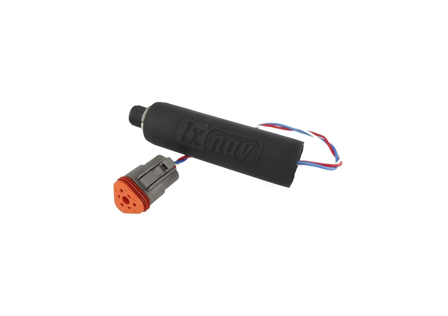
- Fluid level converter (FLC)
- Installation manual
- Male connector kit
Technical Data
General specifications
| Parameter Condition Min Typ Max Unit | |||||
| Operating supply voltage(1) | 8 | 12 | 32 | V | |
| Absolute maximum supply voltage(2) | Non-operating | -50 | 36 | V | |
| Current consumption(1) | 24 | mA | |||
| Load equivalent number | 1 | LEN | |||
| Supply protection | -50V | V | |||
| Operating temperature | -20 | +65 | °C | ||
| Storage temperature | -40 | +85 | °C | ||
| Recommended humidity | 0 | 95 | RH | ||
| Weight | 115 | g | |||
| Housing length | 95 | mm | |||
| Housing diameter | 24 | mm | |||
| Ingress Protection | IP67 | ||||
Note1: Supplied via M12 NMEA2000 connector
Note2: Non-operational, voltages outside of this range may permanently damage the device
Table1: General specifications
NMEA2000 specifications
| Parameter deascription | |
| Compatibility | NMEA2000 compatible |
| Baudrate | 250kbps |
| Connection | A coded M12 connector |
Note1: Supplied via M12 NMEA2000 connector
Table2: General specifications
Connectors on Fluid level converter
NMEA2000 Connector
M12 5-pin A-coded connector on side of unit is compatible with NMEA2000 and has standard pinout.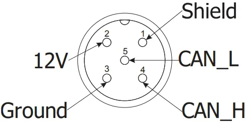
Figure 1: NMEA2000 M12 Male connector pinout (view from unit side)
Deutsch – sensor connector
Pinout
The pinout is shown from the unit side (female connector). Pins on housing are numbered as letters A, B and C.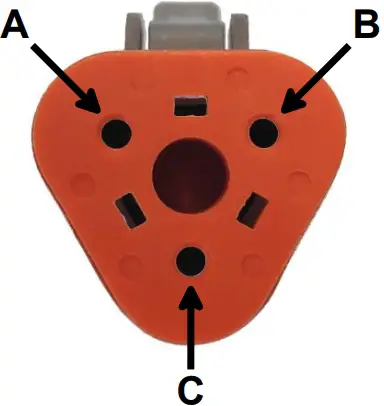
Figure 2: DT06-3S pinout
| Pin Type Description | ||
| A | Analog input B | Wire color – white |
| B | Voltage output | Wire color – red |
| C | Ground | Wire color – blue |
Table 3: Pinout description
Specifications
Voltage output
FLC unit features one switchable 5 V supply outputs for powering sensors. The output has automatic resettable fuse protection against overcurrent, overvoltage and short-circuit faults
| Parameter Condition Min Typ Max Unit | |||||
| Power output voltage | 0 < Iload < 50mA | 4.9 | 5 | 5.15 | V |
| Power output current | Vout > 4.9V | 0 | 50 | mA | |
| Short circuit current limit | Vout = 0V | 50 | 85 | 130 | mA |
| Maximum overload voltage (1) | -25 | 40 | V | ||
Note 1: Voltage forced back into the 5V output pin. Voltage outside of this range may permanently damage the device
Table 4: Power output electrical characteristics
Analog input
Fluid N2K unit features one fully configurable analog input for:
- Voltage sensors: 0-5V
- Resistive: European, ABYC (US) and Asian standards
Analog input has an internal switchable pullup resistor to 5V, thereby relieving the user of manual resistor installation.
| Parameter Condition Min Typ Max Unit | |||||
| Input resistance | 0V < Vin < 30V Pullup disabled | 0.9 | 1.0 | 1.1 | MΩ |
| Input capacitance | 0V < Vin < 30V Pullup disabled | 0.9 | 1.0 | 1.1 | nF |
| Operating input range | 0 | 18 | V | ||
| Absolute maximum input voltage (1) | -36 | 36 | V | ||
| Internal pullup resistance | Pullup enabled | 500 | Ω | ||
Note 1: Continuously applied voltage. Voltage outside of this range may permanently damage the device
Table 5: Analog input electrical characteristics
Accuracy
Shown accuracy limits represent the edges of the acceptable accuracy windows for the above specified operating conditions, typical values may be lower.
| Parameter Condition Value | ||
| Voltage Input Accuracy | 0V < Vin < 18V | < 1 % |
| Voltage Input ADC Resolution | 4.5 mV | |
Table 6: Accuracy specification
Connector crimping
This chapter guides you through crimping wires into the EMU connectors provided. Tools needed are:
- Crimping pliers
- Wire stripper
Figure 3 shows the contents of the sensor connection kit supplied together with FLC unit. It contains (from left to right):
- Endca
- Housing for male terminals
- 3 crimp terminals
- Watertight grommet

Figure 3: Sensor connection kit

For correct crimping procedure follow instruction steps bellow:
Step 1: Pull all necessary wires through grommet.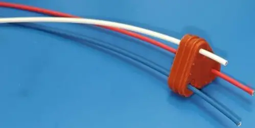
Step 2: Strip wires. Stripped length should be somewhere around 6mm.
Step 3: Insert the wire into the crimp contact and press it with pliers. The result should look like the picture below. Pliers used in this step were from Deutsch HDT-48-00.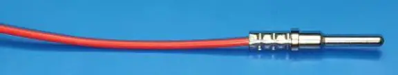
Step 4: Insert three crimped pins into connector on dedicated place. Make sure pins are secured, test them with slight pull outwards. Take care not to mix pins functionality.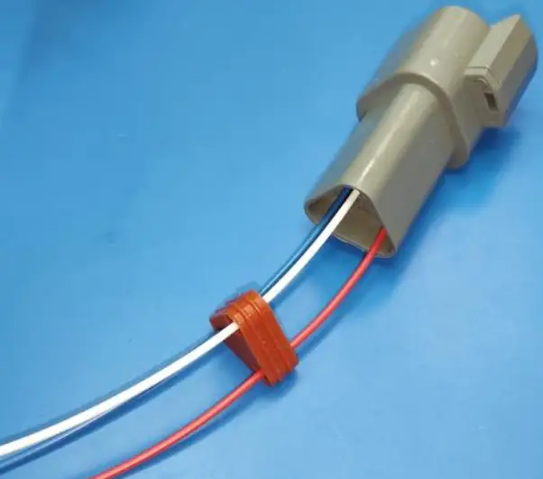
Step 5: Install water grommet on back side of connector.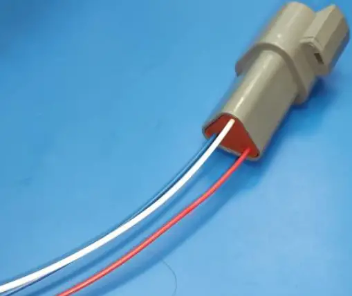
Step 6: From the front side insert secure tab. This prevents crimp contacts to fell out of connector housing.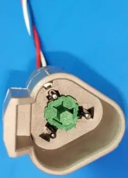
Sensor wiring
All wirings are shown with respect to female connector on Fluid N2K.
Resistive type sensors
Use only ground and analog input connections. Polarity on sensor side is not important.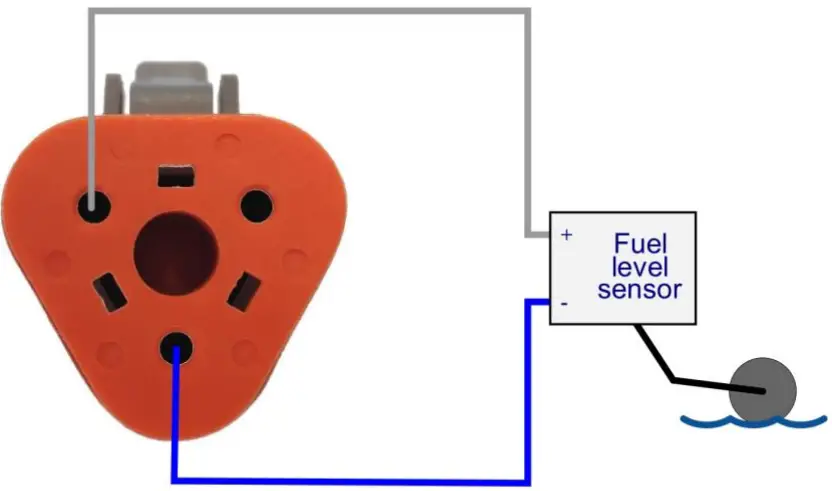
Voltage output type sensors
All three contacts are used in this configuration. V+ and V- terminals are for powering fluid level sensor and analog input measures voltage.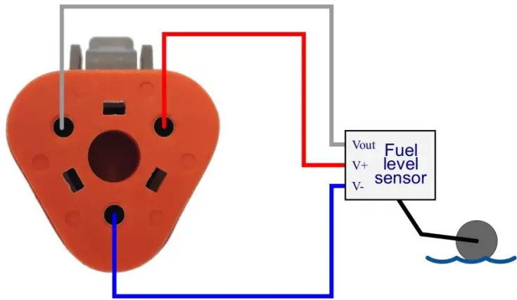
Configuration and calibration
To operate properly, FLCD must be configured prior use. Configuration can be performed via one of LXNAV compatible devices. Configuration menu is accessible under settings menu:
Settings->Network->Connected Devices->LXNAV EMU->Device setup
Configuration
Inside this page user can choose between different options for particular FLC.
Input type
User can select:
- None
- Fluid level
- Voltage reference
Fluid level sensor type
Some standard and generic available options:
- Resistive 240-33 Ohm (US)
- Resistive 3 – 180 Ohm (EU)
- Resistive 105 – 5 Ohm (Asia)
- Resistive 2 – 90 Ohm (EU)
- VDO 0.5 – 4.5 V
- Generic voltage 5 V
- Generic voltage with reference
Fluid type
Types of measured fluid:
- Fuel
- Fresh Water
- Waste Water
- Live Well
- Oil
- Black Water (Sewage)
- Fuel (Gasoline)
Tank capacity
Textbox for capacity of tank.
Calibration
When calibrating fuel level sensor it is necessary to follow some rules. At the beginning go to calibration menu that can be found under this path:
Settings->Network->Device calibration->Fluid level->Fluid level
For the first calibration fuel or any other fluid tank has to be empty. At the beginning there are already two existing calibration points added to calibration table – 0 liters, 0 % and 100 liters, 100 %. Maximum capacity value depends on selected value in configuration menu. User can add up to 10 additional calibration points which increases accuracy of indication due to non-linearity of sensor or different shapes of tanks.
Revision history
| Date | Version | Description |
| April 2020 | 1.0 | Initial release of this manual |


 Instruction Manual")


