![]() riscogroup.com
riscogroup.com
SEISMIC DETECTOR
MODEL: RK66S
INSTALLATION INSTRUCTIONS
INTRODUCTION
The RISCO Seismic Detector has used the protection against break-in attempts of vaults, safes, reinforced concrete walls, steel armored cabinets, and doors. The seismic detector monitors the vibration and temperature of a specific surface and will react to all known types of intruder attacks, such as sledgehammers, diamond head drills, explosives, hydraulic pressure tools, and thermal tools.
The detector can operate both as a regular relay detector connected to any control panel, or as a BUS accessory when connected to RISCO Group’s control panels via the RS485 BUS, empowering it with unique remote control and diagnostic capabilities.
The instructions set forth below describe the RISCO seismic detector in Stand Alone & BUS mode. For BUS installation programming, see RISCO System installation manuals
Main Features:
- Piezo sensor
- Low/High-temperature detection
- Detection range up to 5 meters (16 feet) radius
- Tamper protection
- Anti drilling shield
- Remote sensitivity control
- Analogue signal output
- Bar graph LED indicator
- Remote self-test
- Stand-alone or RISCO BUS connection
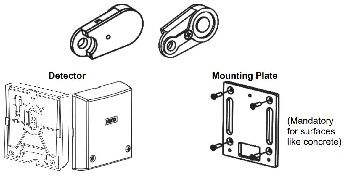
INSTALLATION KIT
Each kit includes:
Wall structure fastening sets:
![]()
Expanding plugs M6 x 16
Flathead machining screw M6 X 16
Metallic structure fastening sets:

Inner Tooth Washer M4
Pan Head Machining Screw M4 X 10
External Test Generator
PCB LAYOUT
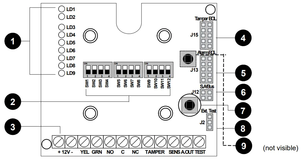
| 1 | Bar Graph LEDs | 2 | Dipswitches (default state) | 3 | Terminal Blocks |
| 4 | Tamper EOL Jumper | 5 | Alarm EOL Jumper | 6 | Stand Alone/BUS Jumper |
| 7 | Tamper (Front ) | 8 | External Test Generator Connector | Tamper (Back) |
MOUNTING THE DETECTOR
- Determine the mounting position. Potential false alarm sources must be accounted for when installing RK66S, Therefore:
- Attach the sensor to a surface as isolated as possible from extraneous vibrations, with close contact between the concrete surface and the detector. For metallic surfaces, remove residual paint from the sensor installation site. Do not use silicone grease between sensor and object!
- For maximum vibration detection, the concrete surface should be smooth. Use the mounting plate (see Figure 2) when mounting on drill-resistant steel, brick, or concrete surfaces. The plate can also be welded onto metallic surfaces.
- Adjust dipswitch settings for sensitivity; time and other parameters (see Dipswitch settings, below) for background vibration – bearing in mind the inverse relation between detection range and sensitivity and the construction material of the object to be monitored. Detectors with high sensitivity can be spaced up to 5m apart on securely protected surfaces (for example, steel), confirmed by hammer or scratch tests.
- Hinged doors, such as those on safes or ATM, and other attachments without continuous acoustic transmission paths should be protected with their own detectors.
- Remove the cover fixing screws to separate the cover from the base, see Figure 1(A) / 2(B).
- Drill holes on the mounting surface, using the detector base or mounting plate as a guide, as follows:
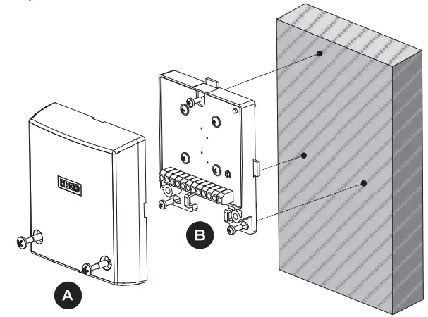
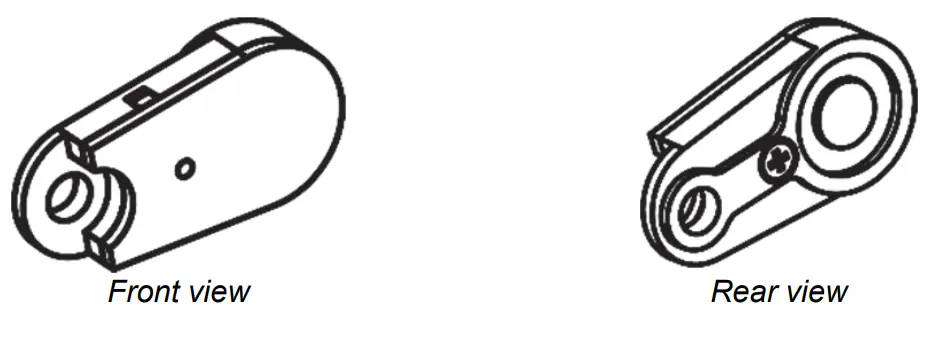
Figure 1: Mounting the detector directly onto a metallic surface
Direct mounting on a metallic surface (Figure. 1)
a. Ensure that the mounting surface is level to within 1/128” (0.1mm).
b. Use the detector base as a drilling template for the three holes (3.2 mm dia.) and tap M4 thread at least ¼” (6 mm) deep. Deburr threaded holes in metal.
c. Fit the detector using the supplied fixing screws, see Figure 1(B).
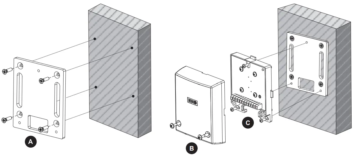
Figure 2: Mounting the detector using the mounting plate. (Note: Affix the mounting plate using fixing screws or optionally, by welding the plate to a metallic surface.) Installation using a mounting plate (Figure 2):
a. (Optional metal welding) Weld the mounting plate along the two provided vertical oblong cutout surfaces. Tap off slag and remove weld splatter from the plate surface.
b. (On concrete) : Never install the detector directly on a bare or plastered concrete surface, since bending forces may cause damage to the seismic sensor. Plaster of less than 10mm need not be removed.
i. Drill four holes for the mounting plate (8 mm dia, min 35 mm depth for an anchor; using a sintered carbide bit.
ii. Also, use the mounting plate as a drilling template for the three threaded detector holes (5 mm dia) at least 3 mm deep.
iii. Insert supplied metal plugs into the drilled hole flush with the concrete surface iv. Ensure that the mounting plate is correctly positioned. Press the mounting plate onto the surface, knock-in the screw with the plug and tighten well. The plate should not be capable of rotation. Fit the detector using the supplied fixing screws, see Figure 2(C).
c. v. (On metal):
i. Use the mounting plate as a drilling template for the four holes (5 mm dia.) and tap M6 thread at least 10 mm deep. Deburr threaded holes in metal.
ii. Also, use the mounting plate as a drilling template for the three threaded detector holes (5 mm dia) at least 3 mm deep.
iii. Affix the mounting plate with the supplied screws. The plate should not be capable of rotation iv. Fit the detector using the supplied fixing screws, see Figure 2(C).
- Connect wiring; Refer to the Terminal Blocks section.
- Set Jumpers; Refer to the Jumper Selection section.
- Set Dipswitches; Refer to the Dipswitch Settings section.
- To verify detector operation, perform:
a. A self-test (See Testing the Detector section).
b. Sensitivity calibration using an external test generator (See
External Test Generator section). - Replace the cover and tighten the cover fixing screws; See Figure 1(A) / 2(B).
TERMINAL BLOCK LAYOUT

Figure 3: Terminal Block Layout
| Terminal Block | Description |
| +12V (RED) | Power supply positive (+) input voltage |
| – (BLK) | Power supply negative (-) input voltage |
| YEL | Used for data communication with RISCO panels (only for BUS connection) |
| GRN | Used for data communication with RISCO panels (only for BUS connection) |
| NO | Alarm Normally Opened relay output, 24VDC.0.1A |
| C | Alarm Common relay output |
| NC | Alarm Normally Closed relay output, 24VDC.0.1A |
| TAMPER | N.C. Tamper Switch, 24VDC.0.1A |
| SENS | Remote sensitivity control for lowering vibration sensitivity for ATM-type dispensers when cash is being disbursed and internal vibration is generated. GND = Low sensitivity Not Connected = Regular sensitivity |
| A.OUT | Analog signal output: Connect a multimeter/scope or an analogic tester between the A.OUT and -12V terminals, to view the noise and signal voltage levels (in parallel to the LED bar representation). In the absence of vibrations, the voltage signal is 0V, and it increases as it detects vibrations. If the voltage measured (in absence of vibrations) doesn’t remain stable but continues to increase, it means that environmental noise is being captured and therefore the detector sensitivity must be reduced. |
| TEST | A short between TEST and GND activates the Remote Test (see Dipswitch Settings 8 and 9). (Not relevant for BUS mode.) |
LED DISPLAY DURING NORMAL MODE
| LED ON | Color | Severity | Description |
| LD1 | Red | Temperature alarm detection | |
| LD2 | Red |  | Vibration alarm detection: Bar graph (from LED8–2) indicating signal power. |
| LD3 | Yellow | ||
| LD4-8 | Green | ||
| LD9 | Green | Power On |
 NOTE:
NOTE:
During Test Mode, the LED displays have a different meaning. Refer to the section:
Testing the detector.
DIPSWITCH SETTINGS
STANDALONE MODE
| Dipswitch | Description (SW7 OFF) | |||||
| SW1 SW2 SW3 | Used to determine the detector’s sensitivity. Sensitivity is a function of coverage area and surface material. | |||||
| SW1 | SW2 | SW3 |  | |||
| *OFF | *OFF | *OFF | ||||
| ON | OFF | OFF | ||||
| OFF | ON | OFF | ||||
| ON | ON | OFF | ||||
| OFF | OFF | ON | ||||
| ON | OFF | ON | ||||
| OFF | ON | ON | ||||
| ON | ON | ON | ||||
| SW4 | Used to detect single and extremely brief and intense signals (including explosions and sled hammers). ON: Enable *OFF: Disable | |||||
| Dipswitch | Description (SW7 OFF) | ||||
| SW5 SW6 | Used to adjust the integration time. In combination with SW1-3 they establish a threshold value; SW5-6 establishes a cumulative alarm signal value which, when exceeding the threshold value, triggers an alarm event. | ||||
| SW5 | SW6 | Duration (in sec.) |  | ||
| *OFF | *OFF | 10 (example: vending machine) | |||
| ON | OFF | 26 | |||
| OFF | ON | 46 | |||
| ON | ON | 80 (example: bank vault) | |||
| SW7 | Used to determine Stand Alone or BUS mode (Ensure that the J12 position (as below) matches the SW7 spec. ) ON: BUS *OFF: Stand Alone | ||||
|
SW8 | Used to determine Local or Remote Test ON: Local. An internal self-test is performed every 24 hours from power-up. Test failure lights up the LEDs (see the Testing the Detector section) and the LEDs remain lit until the next self-test. *OFF: Remote. A test is activated whenever the TEST input is connected to GND. If the test passes, the alarm relay opens for three seconds. | ||||
| SW9 | External test generator ON: Enable External Test Generator *OFF: Disable (internal test) | ||||
| SW10 | Used to enable the temperature sensor (alarm temperature threshold of +85°C (+185°F)) ON: Enable *OFF: Disable (No temp. threshold is set) | ||||
| SW11 | Used to determine LEDs operation ON: Enable *OFF: Disable | ||||
| SW12 | Not used | ||||
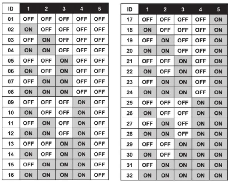
BUS MODE
| Dipswitch | Description |
| SW1-5 | BUS Address |
| SW7 | ON: BUS |
| SW6,8-12 | Not Applicable |
JUMPER SELECTION
| Jumper | Function | |
|
S.A (Stand Alone) /BUS J12 | Used to enable tamper indication during Stand Alone or BUS mode. | |
 | Stand Alone mode (Default). | |
 | BUS connection mode. (See RISCO system programming manuals). | |
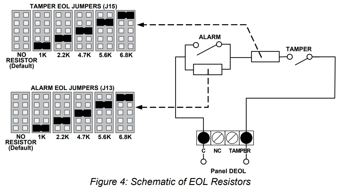
| J13: Alarm EOL J15: Tamper EOL | Jumpers J13 and J15 allow for the selection of Alarm and Tamper resistance (1K, 2.2K, 4.7K, 5.6K and 6.8K) according to the control panel. Follow the terminal block connection diagram in Figure 4 when connecting the detector to a Double End Of Line (DEOL) zone. | |
TESTING THE DETECTOR
RISCO recommends performing a self-test after installation and before final cover mounting. The test can be performed manually (locally or remotely) or automatically every 24 hours
Remote self-test (Manual Test)
This test requires that a command be given in order to be performed.
To activate the remote self-test:
- Ensure that the Dipswitch SW8 is set to OFF.
- Short the TEST terminal block to GND.
- All LEDs will turn on to indicate test commencement and sequentially turn off after each successful parameter test.
The detector unit self-test examines the following parameters:
| LED | Trouble |
| 1 | External power supply failure |
| 2 | Internal voltage faulty |
| 4 | Piezo sensor failure |
| 5 | Temperature sensor failure |
| 3, 6-9 | Not Applicable |
All LEDs will turn off at the end of a successful test, except the POWER LED (LED9) and the alarm relay opens for three seconds. If a malfunction occurs, one of the LEDs remains lit.
Local self-test (Automatic Test)
Ensure that the Dipswitch SW8 is set to ON.
The RK66S detector runs a local/automatic SELF-TEST every 24 hours from the time of initial power on. Test procedure and result presentation is as per the Remote self-test above.
Attach to the concrete surface, using the supplied mounting screw in this hole opening.
The external test generator can be used to:
- Periodically verify the proper functioning of the detector
- Observe the detector’s sensitivity during installation
To use the test generator:
- Connect the test generator to J2 on the PC board (with the polarity resulting from the red wire connected to the plug pin closest to the terminal block, in other words, the lowest)
- Switch SW9 to ON.
- Attach the test generator to the concrete surface.
- Perform the test, as follows:
a. For remote test, see the DIPSWITCH Settings section
b. For the calibration test, Switch SW8 to ON and observe the LEDs
Specifications
| Coverage | Up to 5 meters (16 feet) radius |
| Operating voltage | 9 to 16 VDC |
| Current consumption | Typically 20mA @ 12VDC |
| RFI immunity | According to EN50130-4 |
| Alarm contacts | 24VDC, 0.1A, N/C, and N/O |
| Tamper contacts | 24VDC, 0.1A |
| Alarm contact hold time | 2.5 seconds |
| Operating temperature | -40°C to +70°C (-40°F to 158°F) |
| Storage temperature | -50°C to +70°C (-58°F to 158°F) |
| Ingress protection (IP) rating | IP43 |
| Impact Rating | IK08 |
| RFI immunity | According to EN50130-4 |
| Dimensions (L x H x W) | 102 X 27.5 X 80.2 mm (4.0” X 1.1” X 3.2”) |
| Weight | 220 g ( 7.7 oz) |
In order to continue improving the product, RISCO Group reserves the right to change specifications and/or designs without prior notice.
Ordering Information
| Model | Description |
| RK66S | Seismic Detector |
NOTES
EMC Compliance Statement:
Hereby, RISCO Group declares that this equipment is in compliance with the essential requirements and other relevant provisions of Directive 2014/30/EU.
For the CE Declaration of Conformity please refer to our website: www.riscogroup.com.
Standard Limited Product Warranty
RISCO Ltd., its subsidiaries, and affiliates (“Risco”) guarantee Risco’s hardware products to be free from defects in materials and workmanship when used and stored under normal conditions and in accordance with the instructions for use supplied by Risco, for a period of (i) 24 months from the date of connection to the Risco Cloud (for cloud-connected products) or (ii) 24 months from production (for other products which are non-cloud connected), as the case may be (each, the “Product Warranty Period” respectively). Contact with customers only. This Product Warranty is solely for the benefit of the customer who purchased the product directly from Risco, or from any authorized distributor of Risco. Nothing in this Warranty obligates Risco to accept product returns directly from end-users that purchased the products for their own use from Risco’s customer or from any installer of Risco or otherwise provide warranty or other services to any such end-user. Risco customer shall handle all interactions with its end-users in connection with the Warranty, inter alia regarding the Warranty. Risco’s customer shall make no warranties, representations, guarantees, or statements to its customers or other third parties that suggest that Risco has any warranty or service obligation to, or any contractual privy with, any recipient of a product.
Return Material Authorization. In the event that a material defect in a product shall be discovered and reported during the Product Warranty Period, Risco shall, at its option, and at the customer’s expense, either: (i) accept the return of the defective Product and repair or have repaired the defective Product, or (ii) accept return of the defective Product and provide a replacement product to the customer. The customer must obtain a Return Material Authorization (“RMA”) number from Risco prior to returning any Product to Risco. The returned product must be accompanied by a detailed description of the defect discovered (“Defect Description”) and must otherwise follow Risco’s then-current RMA procedure in connection with any such return. If Risco determines in its reasonable discretion that any Product returned by the customer conforms to the applicable warranty (“Non-Defective Products”), Risco will notify the customer of such determination and will return the applicable Product to the customer at the customer’s expense. In addition, Risco may propose and assess customers a charge for testing and examination of Non-Defective Products.
Return Material Authorization. In the event that a material defect in a product shall be discovered and reported during the Product Warranty Period, Risco shall, at its option, and at the customer’s expense, either: (i) accept the return of the defective Product and repair or have repaired the defective Product, or (ii) accept return of the defective Product and provide a replacement product to the customer. The customer must obtain a Return Material Authorization (“RMA”) number from Risco prior to returning any Product to Risco. The returned product must be accompanied by a detailed description of the defect discovered (“Defect Description”) and must otherwise follow Risco’s then-current RMA procedure in connection with any such return. If Risco determines in its reasonable discretion that any Product returned by the customer conforms to the applicable warranty (“Non-Defective Products”), Risco will notify the customer of such determination and will return the applicable Product to the customer at the customer’s expense. In addition, Risco may propose and assess customers a charge for testing and examination of Non-Defective Products.
BATTERIES ARE EXPLICITLY EXCLUDED FROM THE WARRANTY AND RISCO SHALL NOT BE HELD RESPONSIBLE OR LIABLE IN RELATION THERETO, AND THE ONLY WARRANTY APPLICABLE THERETO, IF ANY, IS THE BATTERY MANUFACTURER’S WARRANTY. Risco makes no other warranty, expressed or implied, and makes no warranty of merchantability or of fitness for any particular purpose. For the sake of good order and avoidance of any doubt:
DISCLAIMER. EXCEPT FOR THE WARRANTIES SET FORTH HEREIN, RISCO AND ITS LICENSORS HEREBY DISCLAIM ALL EXPRESS, IMPLIED, OR STATUTORY, REPRESENTATIONS, WARRANTIES, GUARANTEES, AND CONDITIONS WITH REGARD TO THE PRODUCTS, INCLUDING BUT NOT LIMITED TO ANY REPRESENTATIONS, WARRANTIES, GUARANTEES, AND CONDITIONS OF MERCHANTABILITY, FITNESS FOR A PARTICULAR PURPOSE, TITLE AND LOSS OF DATA. WITHOUT LIMITING THE GENERALITY OF THE FOREGOING, RISCO AND ITS LICENSORS DO NOT REPRESENT OR WARRANT THAT: (I) THE OPERATION OR USE OF THE PRODUCT WILL BE TIMELY, SECURE, UNINTERRUPTED OR ERROR-FREE; (ii) THAT ANY FILES, CONTENT OR INFORMATION OF ANY KIND THAT MAY BE ACCESSED THROUGH THE PRODUCT BY CUSTOMER OR END USER SHALL REMAIN SECURED OR NON DAMAGED. THE CUSTOMER ACKNOWLEDGES THAT NEITHER RISCO NOR ITS LICENSORS CONTROL THE TRANSFER OF DATA OVER COMMUNICATIONS FACILITIES, INCLUDING THE INTERNET, GSM, OR OTHER MEANS OF COMMUNICATIONS AND THAT RISCO’S PRODUCTS, MAY BE SUBJECT TO LIMITATIONS, DELAYS, AND OTHER PROBLEMS INHERENT IN THE USE OF SUCH MEANS OF COMMUNICATIONS. RISCO IS NOT RESPONSIBLE FOR ANY DELAYS, DELIVERY FAILURES, OR OTHER DAMAGE RESULTING FROM SUCH PROBLEMS. RISCO WARRANTS THAT ITS PRODUCTS DO NOT, TO THE BEST OF ITS KNOWLEDGE, INFRINGE UPON ANY PATENT, COPYRIGHT, TRADEMARK, TRADE SECRET, OR OTHER INTELLECTUAL PROPERTY RIGHT
IN ANY EVENT, RISCO SHALL NOT BE LIABLE FOR ANY AMOUNTS REPRESENTING LOST REVENUES OR PROFITS, PUNITIVE DAMAGES, OR FOR ANY OTHER INDIRECT, SPECIAL, INCIDENTAL, OR CONSEQUENTIAL DAMAGES, EVEN IF THEY WERE FORESEEABLE OR RISCO HAS BEEN INFORMED OF THEIR POTENTIAL.
Risco does not install or integrate the product in the end-user security system and is therefore not responsible for and cannot guarantee the performance of the end-user security system which uses the product. Risco does not guarantee that the product will prevent any personal injury or property loss by burglary, robbery, fire, or otherwise; or that the product will in all cases provide adequate warning or protection. The customer understands that a correctly installed and maintained alarm may only reduce the risk of burglary, robbery, or fire without warning, but is not an assurance or a guarantee that such an event will not occur or that there will be no personal injury or property loss as a result thereof. Consequently, Risco shall have no liability for any personal injury, property damage or loss based on a claim that the product fails to give a warning. No employee or representative of Risco is authorized to change this warranty in any way or grant any other warranty.
Contacting RISCO Group
RISCO Group is committed to customer service and product support. You can contact us through our website (www.riscogroup.com) or at the following telephone and fax numbers:
United Kingdom
Tel: +44-(0)-161-655-5500
[email protected]
USA
Tel: +1-631-719-4400
[email protected]

(NOTE: Only RK66S000000A is certified with INCERT)
All rights reserved.
No part of this document may be reproduced in any form without prior written permission from the publisher.
© RISCO Group 10/2018 5IN1393 K


