![]() ZT-25 Series ZigBee Wireless 8-ch Thermistor Input Module
ZT-25 Series ZigBee Wireless 8-ch Thermistor Input Module
User Manual
ZT-25 Series ZigBee Wireless 8-ch Thermistor Input Module
Warranty
All products manufactured by ICP DAS are under warranty regarding defective materials for a period of one year, beginning from the date of delivery to the original purchaser.
Warning
ICP DAS assumes no liability for any damage resulting from the use of this product. ICP DAS reserves the right to change this manual at any time without notice. The information furnished by ICP DAS is believed to be accurate and reliable. However, no responsibility is assumed by ICP DAS for its use, nor for any infringements of patents or other rights of third parties resulting from its use.
Copyright
Copyright © 2013 by ICP DAS. All rights are reserved.
Trademarks
Names are used for identification purpose only and may be registered trademarks of their respective companies.
Technology Support
If you have any problems, please feel free to contact us via email at [email protected]
What’s in the shipping package?
The shipping package includes the following items:
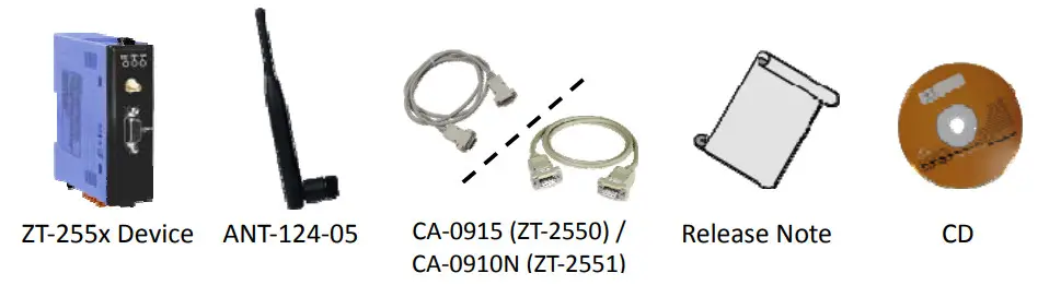
If any of these items are missing or damaged, please contact your local distributor for more information. Save the shipping materials and cartons in case you want to ship the module in the future.
More Information
- Documentation:
CD: \Napdos\ZigBee\ZT_Series\Document
http://ftp.icpdas.com/pub/cd/usbcd/napdos/zigbee/zt_series/document - Software:
CD: \Napdos\ZigBee\ZT_Series\Utility
http://ftp.icpdas.com/pub/cd/usbcd/napdos/zigbee/zt_series/utility
Introduction to ZigBee
ZigBee is a specification for a suite of high-level communication protocols using small, low-power digital radios based on the IEEE 802.15.4 standard for personal area networks. ZigBee devices are often used in mesh network form to transmit data over longer distances, passing data through intermediate devices to reach more distant ones. This allows ZigBee networks to be formed ad-hoc, with no centralized control or high-power transmitter/receiver able to reach all of the devices. Any ZigBee device can be tasked with running the network.
ZigBee is targeted at applications that require a low data rate, long battery life, and secure networking. ZigBee has a defined rate of 250 kbit/s, best suited for periodic or intermittent data or a single signal transmission from a sensor or input device. Applications include wireless light switches, electrical meters with in-home-displays, traffic management systems, and other consumer and industrial equipment that requires short-range wireless transfer of data at relatively low rates. The technology defined by the ZigBee specification is intended to be simpler and less expensive than other WPANs.
Introduction to the ZT‐255x Module
The Basis of ZT-255x Series Product
The ZT-2550 and ZT-2551 series modules are small-sized wireless ZigBee converters based on the IEEE802.15.4 standard that allow RS-232, RS-485 interface to be converted to a personal area ZigBee network. The typical transmission of ICP DAS ZT series ZigBee products is 700 meters (LOS, line of sight), with a transmission frequency range of between 2.405 GHz and 2.48 GHz, separated into 5 MHz sectors, providing 16 channels and 16384 PAN IDs. ZT-2000 series is not only a long distance wireless converter but also can act a ZigBee router to extend the transmission range and improve the quality of wireless signal.
ZT-2000 series products are specification for a suite of high level communication protocols using small, low-power digital radios module, which are fitted the ZigBee 2007 (ZigBee Pro) of ZigBee Alliance. In the ZigBee network, it is only allowed one ZigBee Host and called “ZigBee Coordinator”, ZT-2550 series products, are used to initialize and manager the routing. In ddition, One ZigBee network are able to manager 255 ZigBee router and responsible for receiving or bypassing data from parent or child node.
The Benefits of ZT-255x Series Product A Windows compatible GUI configuration utility is available. The utility allows users to set different configurations based on the type of application, together with several of required ZigBee variables such as Pan ID. The friendly user interface is also helping user be familiar with ZT-2000 series.
For more information, please refer to the relevant documents for these devices, which can be found at following link:
http://ftp.icpdas.com/pub/cd/usbcd/napdos/zigbee/zt_series/document
Hardware Information
3.1 Specifications
| Part Number | ZT-2550 (Coordinator) | ZT-2551 (Router) | |
| Hardware | |||
| MCU Module | 8-bit microprocessor | ||
| Temporary Buffer Size | 256 Bytes | ||
| LED | Green | ZigBee Net | |
| Yellow | ZigBee RxD | ||
| Red | ZigBee Power | ||
| Communication Interface (COMO) | |||
| COMO | RS-232 | RS-232 (TxD, RxD and GND); | |
| D-Sub 9 Female, Non-isolated | D-Sub 9 Male, Non-isolated | ||
| RS-485 | RS-485 (DATA+, DATA-; internal ASIC self-tuner); Non-isolated | ||
| Data Format | N81, N82, 071, 081, E71, E81, S71, S81, M71, M81 | ||
| Power | |||
| Protection | Power Reverse Polarity Protection | ||
| EMS Protection | ESD, Surge, EFT | ||
| Required Supply Voltage | +10 Voc — +30 Vc,c | ||
| Power Consumption | 1 W(Max.) | ||
| Mechanism | |||
| Casing | Plastic | ||
| Flammability | UL 94V-0 materials | ||
| Dimensions | 33 mm x 78 mm x 107 mm (W x L x H) | ||
| Installation | DIN-Rail | ||
| Environment | |
| Operating Temperature Storage Temperature | -25°C – +75°C -40°C – +80°C |
| Relative Humidity | 5 – 95% RH (non-condensing) |
| Wireless | |
| RF Channels | 16 |
| RF Transmit Power | 11 dBm |
| Antenna (2.4GHz) | 5 dBi Omni-directional antenna |
| Transmit Range (LOS) | 700 m (Typical) |
| Max. Slaves Supported | 255 |
| EMI Certification | CE/FCC, FCC ID |
WARNING!![]() Installation Requirements Before to Use
Installation Requirements Before to Use
In compliance with the EN 60950-1 declaration, ZT-2000 series modules are NOT portable devices and should be DIN-Rail mounted. The ZT-2000 series is NOT designed for the general public. Please check the ZT-2000 series is set ready and well mounted before operating, beware of the hot part or surface when maintaining or reinstalling.
3.2 ZT‐255x Front View
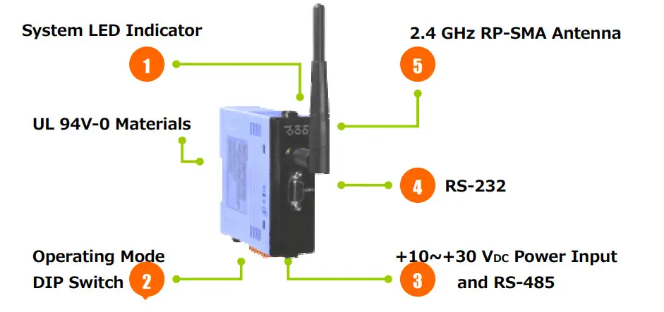
- LED Indicator Status
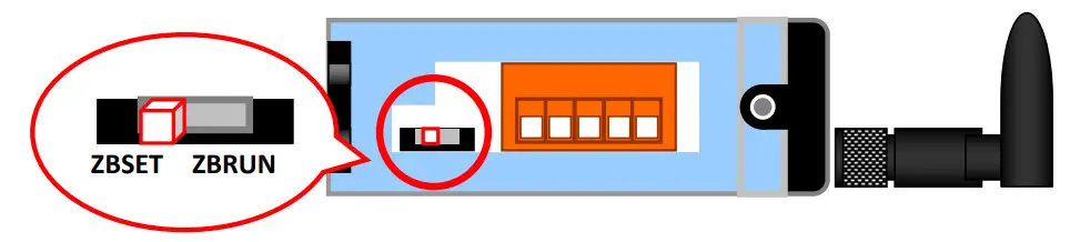
LED Indicator LED Color Explain ZigBee Net Green The status of ZigBee network. ZigBee RxD Yellow The status of ZigBee communication ZigBee PWR Red The status of module board - Operating Mode DIP Switch
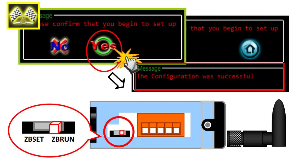
→ ZBSET: Configuration mode is able to use ZT Configuration Utility to configure via the RS-232 or RS-485 interface.
→ ZBRUN: Transmit mode is used to transmit data to the remote device. - RS-485 and +10 VDC ~+30 VDC Power Input
→ The RS-485 and RS-232 are communicable via the same UART.
→ The ZigBee PWR indicator will be steady light if correct power input. - RS-232
→ The RS-485 and RS-232 are communicable via the same UART. - 2.4 GHz RP-SMA Omni-directional Antenna
→ If there is any requirement for extension cable, it must be a connector with the type RPSMA and resistance 50 Ohm. Ex. 3S001-1, 3S003-1…etc
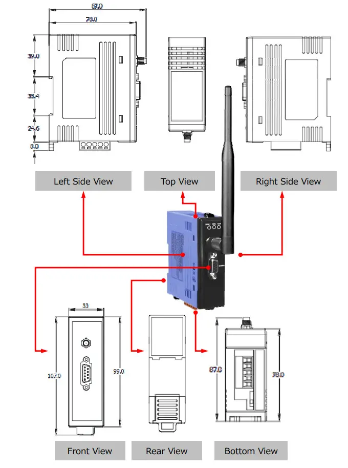
3.3 Dimensions (Units: mm)
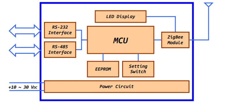
3.4 Block Diagram
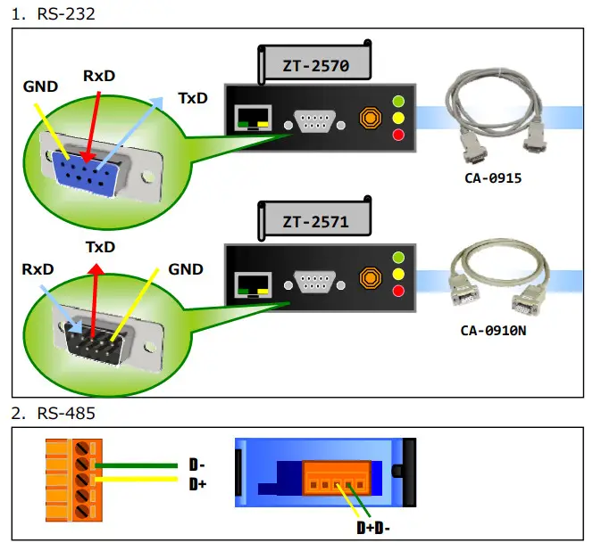
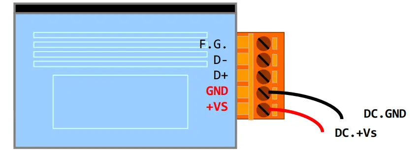
3.5 Wire Connections
Setting up the ZT‐255x module
4.1 Introduction of configurations
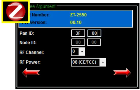
- “Pan ID” is the group identity of a ZigBee network, and must be the same if they are in the same ZigBee network. (Valid values range from 0x0000 to 0x3FFF)
- “Node ID” is the identity of the ZigBee module.
The identity number must be unique if it is in the same ZigBee network as other ZigBee module. (Valid values range from 0x0001 to 0xFFF7 for a ZigBee Router, but is fixed to 0x0000 for a ZigBee Coordinator) - “RF Channel” indicates the radio frequency channel, and must be set to the same channel if the module is in the same ZigBee network as other ZigBee modules.
| Channel | 0x00 | 0x01 | …… | 0x0F |
Use application tools or analyzers to detect the wireless signal, chose a RF Channel which has not been occupied. E.g. Wifi Analyzer
As below the screenshot shown, there were several WLANs over the channel 1, 6 and 11. Referring to the channel table of WiFi and ZigBee, the channels of ZigBee 4, 9, E and F are not overlap with WLAN. So, the RF Channel 4, 9, E and F of ZigBee are recommended in this case. 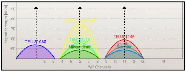
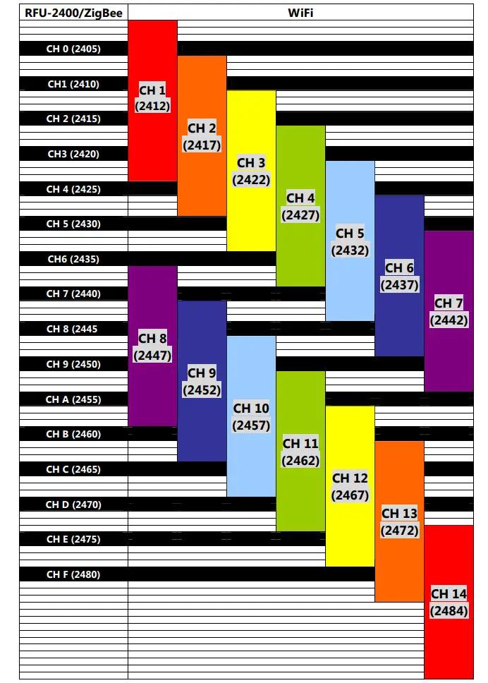
- RF Channel Table to ZigBee(802.15.4) and WLAN(IEEE 802.11b/IEEE 802.11g)
“RF Power” denotes the wireless transmit power value.
| Code | Note |
| 0x0F | Typical Maximum |
| 0x08 | Fit the CE/FCC certification |
| 0x00 | Typical Minimum |
※ The parameter adjustment purely personal behavior, ICP DAS can not guarantee to pass CE/FCC certification if adjusting this parameter, nor assume any liability because of the adjustment parameters derived from the RF Power.
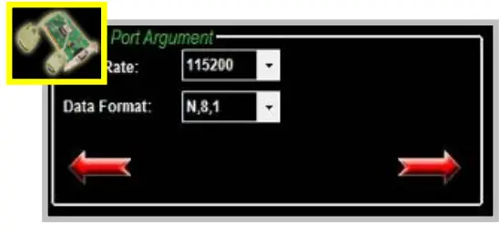
“Baud rate & Data Format” values are based on the configuration of the serial port.
| Item | Specification |
| Parity | None, Odd, Even, Space and Mark |
| Data Bit | 7, 8 |
| Stop Bit | 1, 2 |
| Baud rate | 1200 to 115200 bps |
Communication
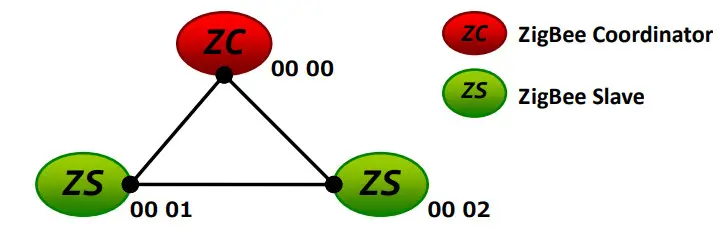
Speed (The Interval Time of Sending Broadcast Frame):
The data payload of ZT-2000 series modules is 79 bytes. Once the data is more than 79 bytes, it will be divided into several packets. This parameter is used to decide the interval time of sending broadcast frame in order to prevent the network crashes. Please fill in the number of ZT-2000 slaves nearby the ZigBee Coordinator.
Example: 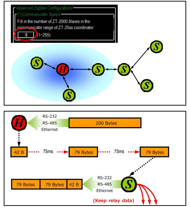
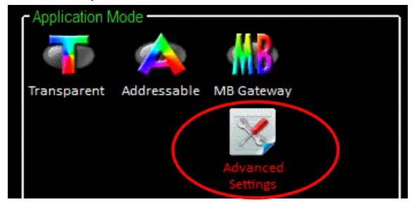
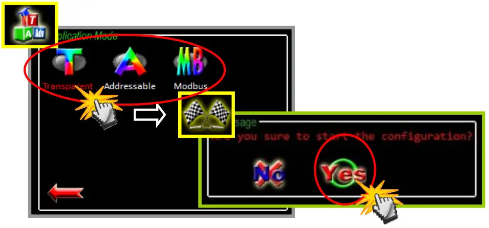
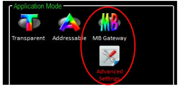
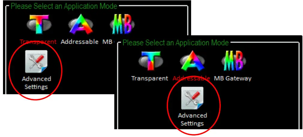
Application Mode can be changed and used for certain specific purpose.
The above schematic diagram is showing what the difference of using different application modes.
a. Transparent Mode is the default application mode, and always transmits data to the remote device via broadcasting. Unless there are specific purposes, the application mode can be retained as default.
The mode always bypasses data to remote side via broadcasting. If there is no particular purpose, user only keeps this application mode.
| Module | Frame Type | Note |
| ZT-2550 | Broadcast | Data will be sent to all ZigBee slaves |
| ZT-2551 | Unicast | Data will only be sent to the coordinator |
[Eg1] When ZT-2550 ZigBee Host sends “DATA_01” via broadcasting frame, → Both of the ZigBee slave 0x0001 and 0x0002 will receive the DATA_01.
※Broadcasting type frame, data will be sent to every ZigBee slaves in the same ZigBee network
[Eg2] When the ZigBee slave 0x0001 sends “DATA_02” via unicast frame, → Only ZT-2550 receives DATA_02.
※Unicast type frame, data will only be sent to the ZigBee host 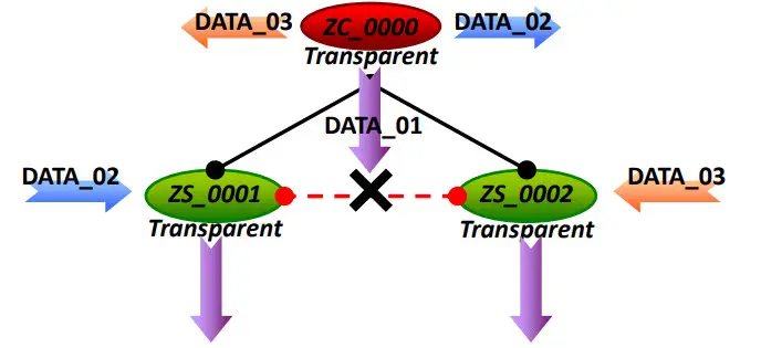
※ There is an “Advanced Settings” for some specific user, please refer the section 7.3 ”Non-addressable Device Communication” to user manual for more information.
b. Addressable Mode is an advanced application mode and it is used to send data to specific ZigBee nodes. It is not only used to transmit data to specific ZigBee slaves from host but also transmit data between ZigBee slaves. A 5-byte ASCII code should be added as an index before the data.
| Module | Frame Type | Note |
| ZT-2550 ZT-2551 | Unicast | Data will be sent to a specific ZigBee slave. Format: “:AAAA” + Data |
[Eg1] When ZT-2550 ZigBee Host sends “:0001DATA_01” via unicast frame, →Only the ZigBee Slave 0x0001 receives DATA_01.
※Unicast type frame, data will be only sent to the specific ZigBee node
[Eg2] When ZigBee slave 0x0001 sends “:0002DATA_02” via unicast frame
→Only the ZigBee Slave 0x0002 receives DATA_02.
※Unicast type frame, data will be only sent to the specific ZigBee node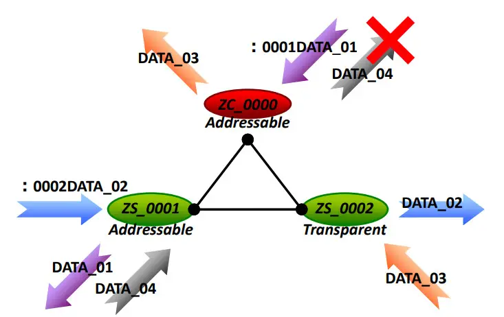
※ There is an “Advanced Settings” for some specific user, please refer the section 7.3 ”Non-addressable Device Communication” to user manual for more information.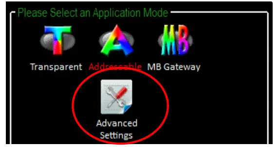
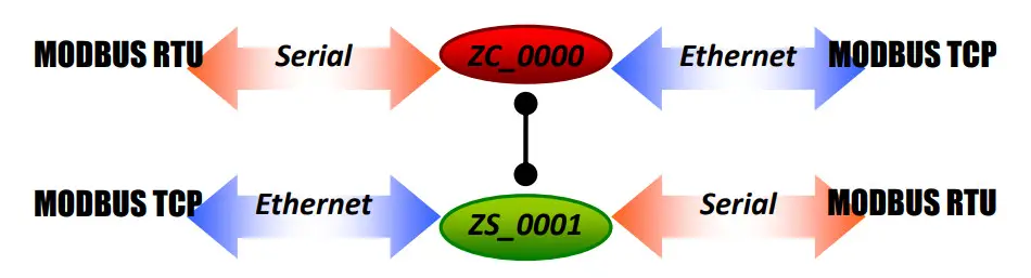
c. Gateway Mode is an advanced application mode and it is used to convert the Modbus protocol. But there is only RS-232 and RS-485 interface supported in the ZT-255x device, so the data is always regarded as Modbus RTU format transmission.
| Module | Frame Type | Note |
| ZT-2550 | Broadcast (Default) | Data is sent to all of ZigBee slaves |
| Unicast (Advanced) | Data will be sent to a specific ZigBee slave. The Address of DCON/Modbus command is regarded as destination ZigBee address | |
| ZT-2551 | Unicast | Data only be sent to coordinator |
[Eg1] When ZT-2550/ZT-2570 receives data “MRTU_CMD_01” from serial port, →ZT-2551 will output the data “MRTU_CMD_01” to serial port directly.
[Eg2] When ZT-2570 receives data “MTCP_CMD_02” from Ethernet, →ZT-2551 will convert protocol then output “MRTU_CMD_01” to serial port.
[Eg3] When ZT-2551 transmits the acknowledgement “MRTU_ACK_03”,
→ZT-2550/ZT-2570 will response the acknowledgement “MRTU_ACK_03” to serial port directly.
→ZT-2570 will convert protocol then output “MTCP_CMD_01” to Ethernet.
※Unicast type frame, data will only be sent to the ZigBee host
※ There is an “Advanced Settings” to the Gateway Mode for some specific user, please refer the section 7.2 “DCON/Modbus Device Communication” for more information.
4.2 Connecting the Power and Host PC
- Confirm that the DIP switch is set to the “ZBSET” position.

- Connect the DC.GND and DC.+Vs pins with 10 to 30V power supply.
 SAFTY INSTRUCTION NOTES
Before connecting the power source to the power input pins, ensure that both the installation of the unit in the completed system, and the DC power source (SELV, Limited Power Source) that is intended to be connected to the power input pins (DC.+Vs / DC.GND) comply with the requirements of EN 60950-1. - Connect either the RS-232 or RS-485 interface to configure the ZT-255x.
→ RS-232:
- Enable the power. It means that the ZT-255x start-up procedure has been completed. If the red LED has changed from blinking to a steady light.
 SAFTY INSTRUCTION NOTES
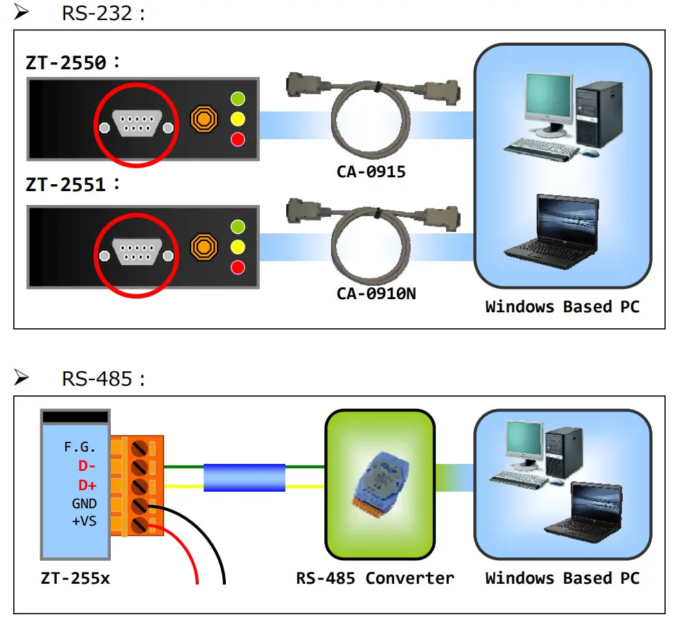
4.3 Configuring ZigBee Setting
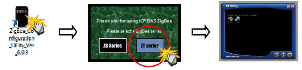
- Launch the “ZT Configuration Utility” and click the [ZT Series] button.

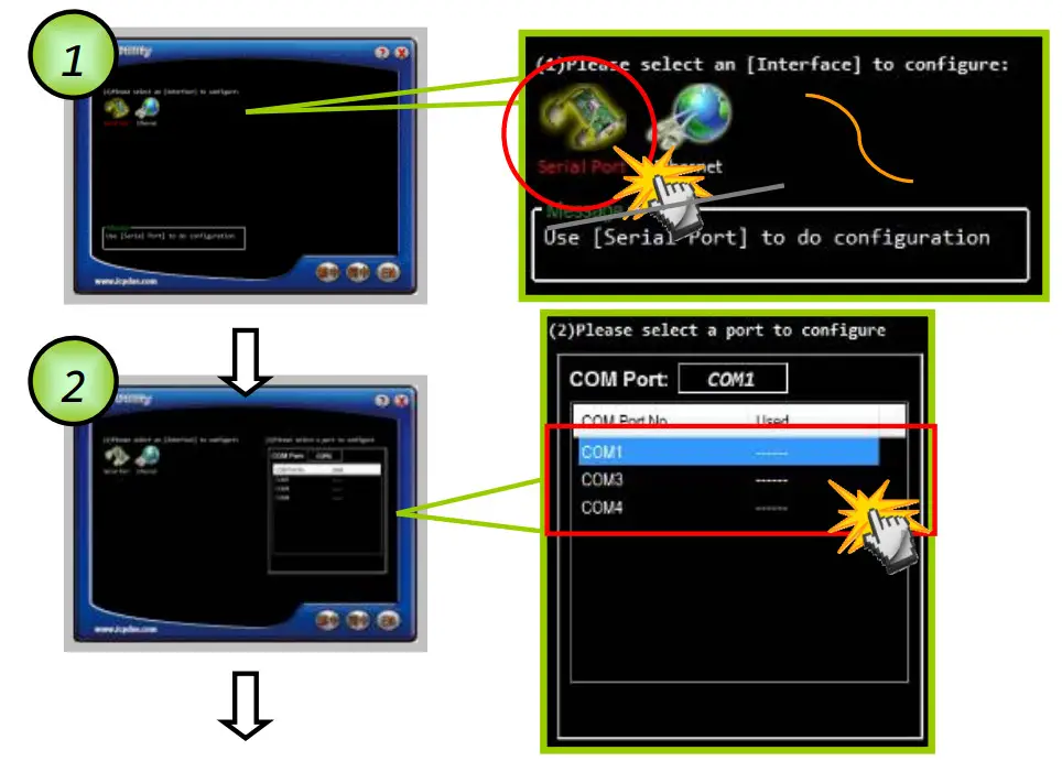
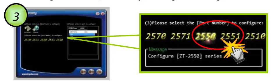
- Click the [Serial Port] icon and then select the COM Port number.

- After selecting the COM Port number, a list of model numbers will be displayed. Select the name of the module that you want to configure. After clicking the button, the utility will begin checking the connection.

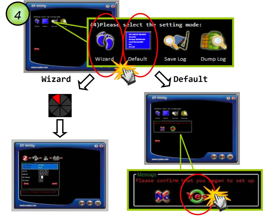
- Once a connection is established, select either the [Default] or the [Wizard] function from the settings mode page.

- Whether you select either the [Default] or the [Wizard] option for performing configuration, both are used to configure the Pan ID, Node ID, RF Channel, RF Power, Baud rate, Data Format, Application Mode and so the relevant parameters.

- Pan ID/Node ID/RF Channel/RF Power For more details, please see section 4.1.

- Baud Rate and Data Format

- Application Mode
For more details, please see section 4.1.
- Once the module configuration has been completed, the message “The Configuration was successful” will be displayed. Return the DIP switch to the “ZBRUN” position and reboot the ZT-255x device.


4.4 Test Communications Method (1)
Connect both the ZT-2550 and ZT-2551 to the Host PC via the RS-232 port. You may need to use two serial port tools to simulate the data transmission. 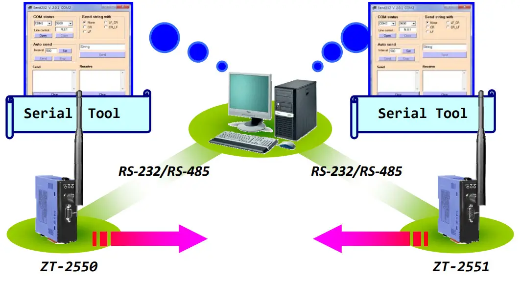
Method (2):
Use the DCON Utility on the Host PC to search for ZT-2000 series I/O modules.
If there any devices are found, it means that the configuration is correct. 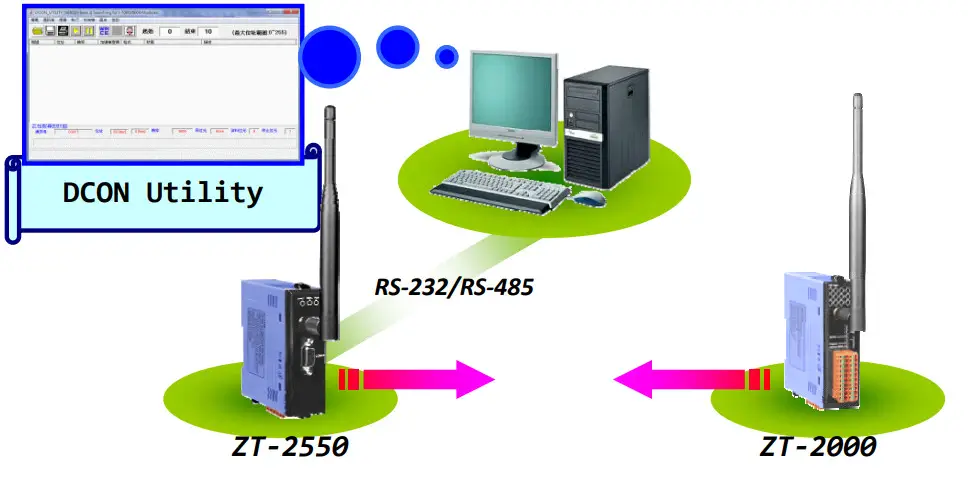
Applications
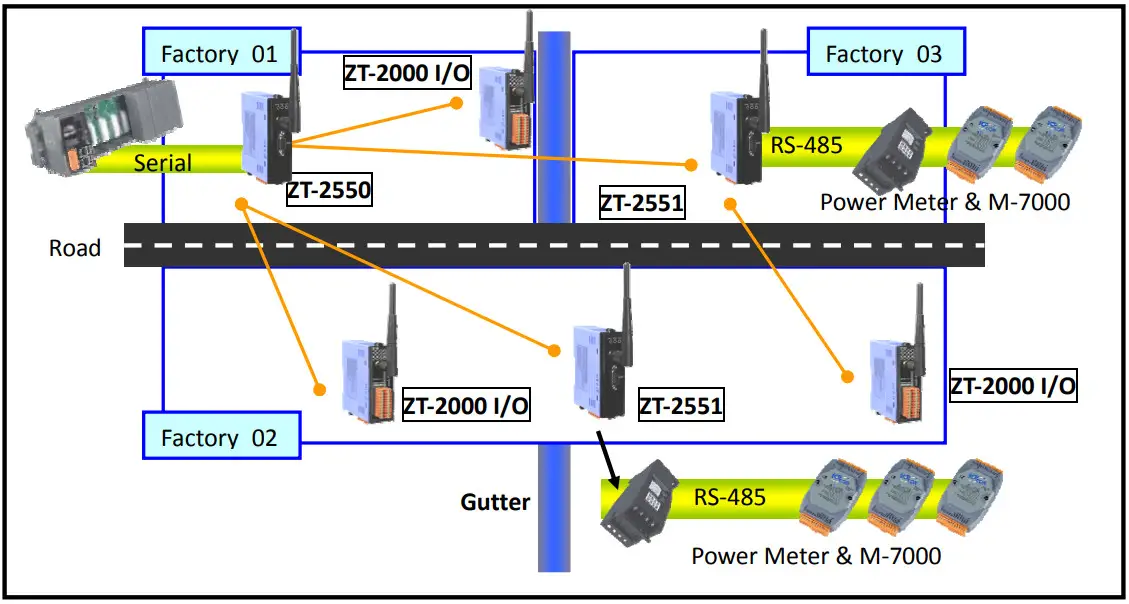
- The ZT-255x is suitable for using in which is wiring difficult and low data rate environment.
Eg. The I/O nodes are across the road, building or gutter….
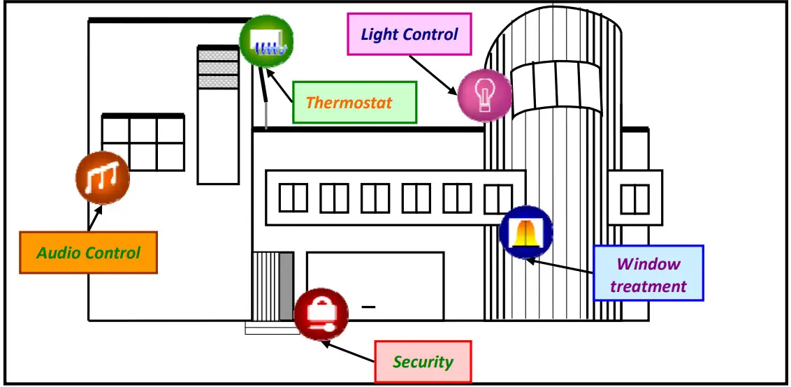
- ZT-255x is suitable to use in monitoring and controlling.
Eg. Smart energy, Home automation…
Troubleshooting
6.1 Technical Support
If you have any difficulties using your ZT-255x series module, please send a description of the problem to [email protected]
Include the following items in your email:
- A description to the communication protocol for more information.
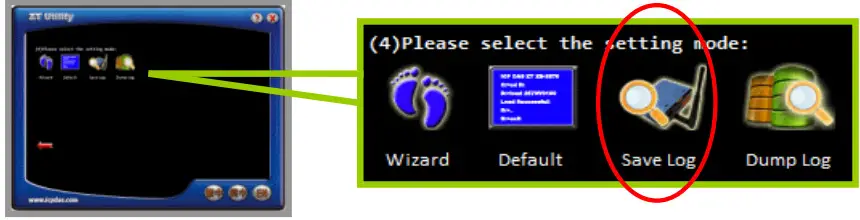
- A copy of the configuration file for the ZT-255x module. This file can be obtained using the procedure outlined below and should be attached to your email. a. Set
the DIP switch of the ZT-255x device to the [ZBSET] position then reboot the device. Launch the ZT Configuration Utility and select [Save Log] icon to save the configuration of the ZT-255x as a file. b. After clicking the [Save Log] icon, enter the “File Name” and the “File Path” in the Windows “Save” dialog box. Once the configuration has been successfully saved, the following message will be displayed.
 b. After clicking the [Save Log] icon, enter the “File Name” and the “File Path” in the Windows “Save” dialog box. Once the configuration has been successfully saved, the following message will be displayed.
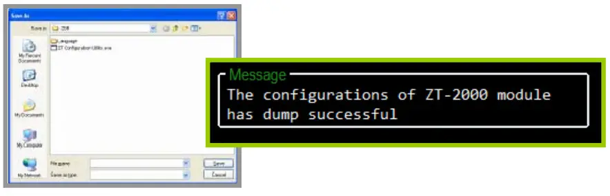
Appendixes
7.1 LED Indicator Status
| LED Indicator | Status | Introduction |
| ZigBee Net (Green LED) | ZigBee Coordinator (Host) | |
| Steady Lit | ZigBee network is Establish | |
| Blink to Steady Lit | Rejoin ZigBee Network or It has Occupied | |
| ZigBee Router (Slave) | ||
| Steady Lit | The Signal is Strong | |
| Blinking (500 ms) | The Signal is Available | |
| Blinking (1s) | The Signal is Weak | |
| Blinking (2s) | The Signal is Unstable or There is no Available | |
| ZigBee RxD (Yellow LED) | The status of ZigBee communication | |
| Blinking | Receiving ZigBee Data | |
| Steady Unlit | No ZigBee Data Received | |
| ZigBee PWR (Red LED) | The status of module board | |
| Steady Lit | Power ON | |
| Blinking (200ms) | Module Initialization Failure | |
| Blinking (500ms) | Configuration Mode | |
| Blinking (1s) | Watchdog Enabled | |
| Steady Unlit | Power OFF | |
7.2 DCON/MODBUS Module Communication
ZigBee is defined as a low-power and low data rate wireless transmission protocol. In order to prevent excessive transmission loading to the ZigBee network, there is an advanced setting to the Gateway Mode to set the wireless frame type, which is used to select either the Broadcast Frame or Unicast Frame to transmit data. 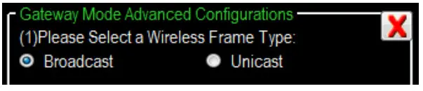
Once the Unicast Frame is selected, the Address of DCON or Modbus instructions will be regarded as the destination address to the ZigBee. So, the DCON/Modbus devices should be connected to corresponding address of ZigBee module. 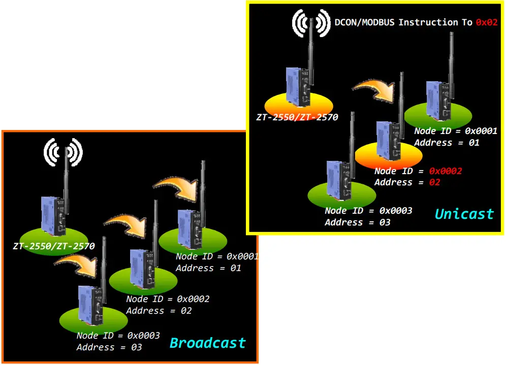
For some applications, there are several DCON or Modbus devices should be connected to the same ZT-2551 modules. 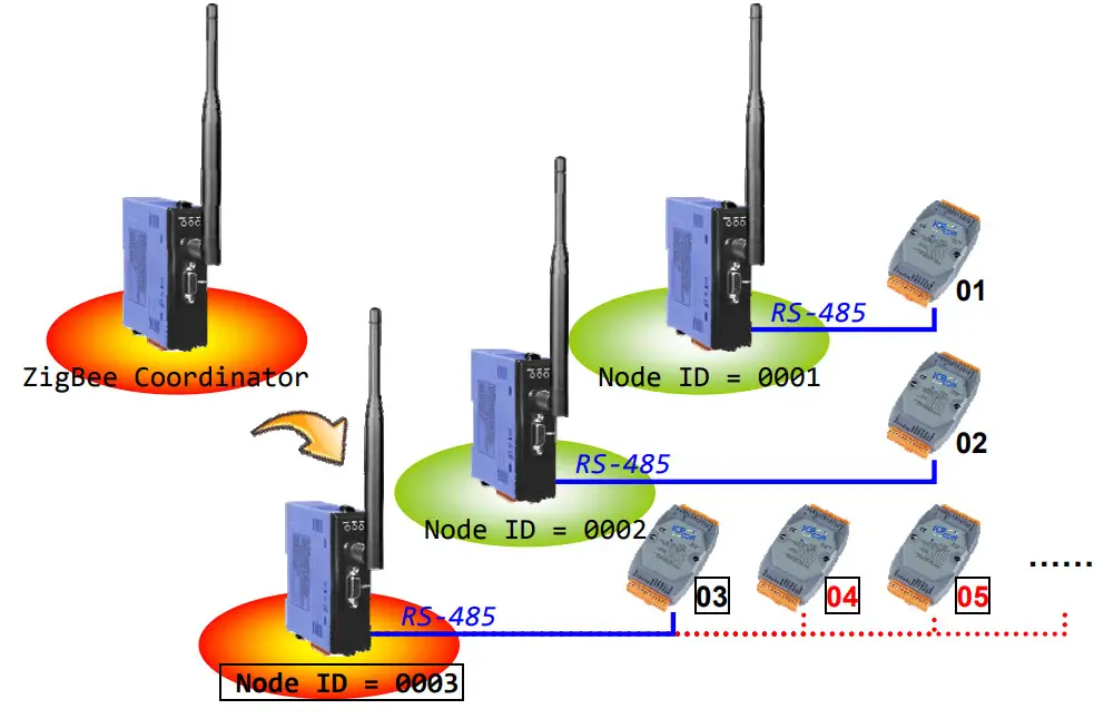
Although the addresses of these additional DCON and Modbus devices are not corresponding to the relative ZigBee module, but there is an Address Mapping function supported for redirection to the correct destination address of ZigBee module. User only fills in the relationship of address mapping for redirection via the ZT-2000 Configuration Utility. 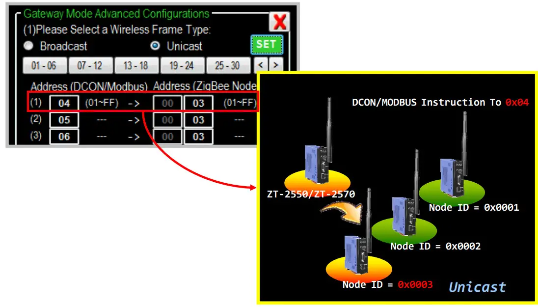
7.3 Non‐addressable Device Communication
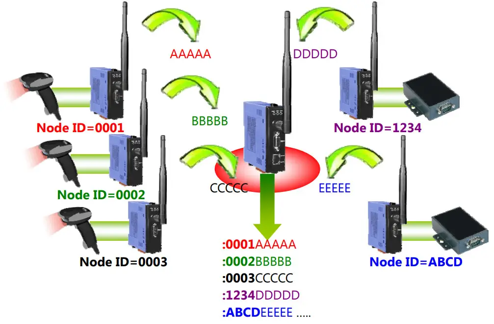
In some applications, there are some devices can not be addressable and they even take the initiative to reply data. Once these non-addressable devices send data to the user’s controller via ZigBee, the user program can not identify which device sends this data.
For example, there are several barcode readers and RS-232 device connected to the ZT-2551. Once these devices are triggered to reply data, the controller will not be able to identify which end device sends the data. 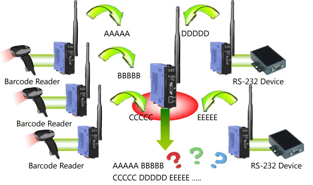
In order to provide a solution for the similar application using non-address device, there is an advanced setting to the Transparent Mode and Addressable Mode to show the Node ID of the remote ZigBee device which is connected to the userʼs end-device.
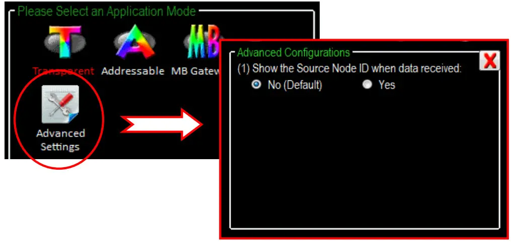
When the advanced function is enabled, the Node ID will be added in the “:AAAA” format in front of the original data and then be output once receiving remote data.
ICP DAS, ZT‐2550/ZT‐2551 User Manual, Version 1.3 Page 30
Copyright @ 2013 by ICP DAS Co., Ltd. All Rights Reserved.


