VTS5000D Control and Modbus Communication
Description
| Index Number | Description | Sanyu Customized Model |
| 1-2-1208-5024 | FC 0,75kW 3PH 3~400V VFD | VTS5000D-0R7G-4 |
| 1-2-1208-5025 | FC 1,5kW 3PH 3~400V VFD | VTS5000D-1R5G-4 |
| 1-2-1208-5026 | FC 2,2kW 3PH 3~400V VFD | VTS5000D-2R2G-4 |
| 1-2-1208-5033 | 0,75kW 1PH 1~230V VFD_S2 | VTS5000D-0R7G-S2 |
| 1-2-1208-5034 | 1,5kW 1PH 1~230V VFD_S2 | VTS5000D-1R5G-S2 |
| 1-2-1208-5035 | 2,2kW 1PH 1~230V VFD_S2 | VTS5000D-2R2G-S2 |
THE FOLLOWING MANUAL ASSUMES GOOD KNOWLEDGE OF TECHNICAL DOCUMENTATION INCLUDED WITH THE AIR HANDLING UNIT (AHU). THIS MANUAL CONSIDERS ONLY THE CONTROL AND COMMUNICATION CIRCUITS. THE INSTALLATION OF THE FREQUENCY CONVERTER AND INSTALLATION OF MAINS AND MOTOR CABLES SHOULD BE DONE ACCORDING TO THE VTS5000D MANUAL.
FOR ALL CONFIGURATIONS SET THE COMMON PARAMETER LIST
| Parameter | Code | Value | Comments |
| Maximum frequency | P105 | 100 | |
| Acceleration Time 1 | P107 | 45 | recommended 45 sec. |
| Deceleration Time | P108 | 45 | recommended 45 sec. |
| Rated motor voltage | P209 | 380 | 0-500V |
| Rated motor current | P210 | * | Scale: 0.1 A |
| Motor rated speed | P212 | * | |
| Number of motor poles | P213 | * | |
| Rated motor slip | P214 | ** | 0.1HZ |
| Rated motor frequency | P215 | 50 | |
Motor overload protection selection | P816 | 1 | 0: Prohibit |
CONFIGURATIONS WITHOUT VTS CONTROLS
Local control using integrated control panel
Set additional parameters:
| Parameter | Code | Value | Comments |
| Main frequency source X selection | P101 | 3 | Local keypad potentiometer setting mode |
| Start signal selection | F102 | 0 | 0: Operation panel (FWD/REV/STOP) 1: I/O terminal 2:Communication(RS485) |
| Maximum frequency | P105 | 100 | |
| Minimum frequency | P106 | 20 | |
| Switch AI jumper to I to choose analog current input | |||
| AI minimum voltage input | P300 | 0V | 0.00V~P301 |
| AI maximum voltage input | P301 | 10V | |
Use the RUN and STOP/RST buttons to control the drive Use buttons to set frequency
Remote control with three speeds
Set additional parameters:
| Parameter | Code | Value | Comments |
| Main frequency source X selection | P101 | 6 | Multi-speed |
| Start signal selection | F102 | 1 | 0: Operation panel (FWD/REV/STOP) 1: I/O terminal 2:Communication(RS485) |
| SET multi function terminal REV | P316 | 9 | Multi -speed 1 |
| SET multi function terminal S1 | P317 | 10 | Multi -speed 2 |
| SET multi function terminal S2 | P318 | 11 | Multi -speed 3 |
| Multi speed 1 (speed I) | P503 | * | 20 – 100Hz |
| Multi speed 2 (speed II) | P504 | * | 20 – 100Hz |
| Multi speed 3 (speed III) | P505 | * | 20 – 100Hz |
| RA,RC | P325 | 3 | 3:Alarm (stop) |
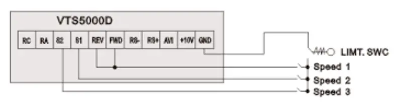
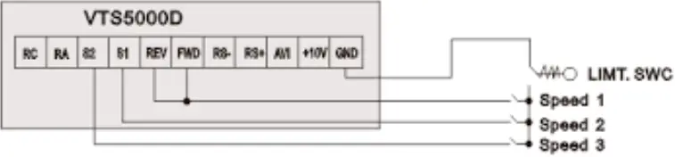
Wire the I/O terminal of the VTS5000D inverter according to the Figure 1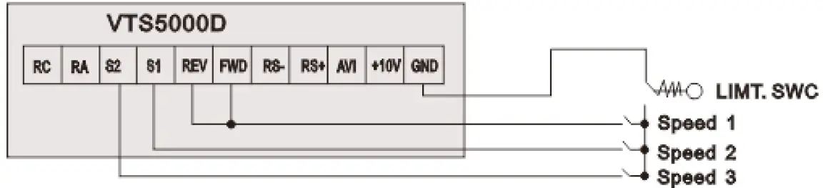 Use FWD/REV/S1/S2 inputs to set desired drive function (1=on,0=off)
| 0000 = STOP | |
| 1100 = START, 1ST SPEED | Value is P503 |
| 1110 = START, 2ND SPEED | Value is P503+P504 |
| 1111 = START, 3RD SPEED | Value is P503+P504+P505 |
EXHAUST UNIT WITH VTS CONTROL SYSTEM
| Parameter | Code | Value | Comments |
| Main frequency source X selection | P101 | 6 | Multi-speed |
| Start signal selection | F102 | 1 | 0: Operation panel (FWD/REV/STOP) 1: I/O terminal 2:Communication(RS485) |
| SET multi function terminal REV | P316 | 9 | Multi -speed 1 |
| SET multi function terminal S1 | P317 | 10 | Multi -speed 2 |
| SET multi function terminal S2 | P318 | 11 | Multi -speed 3 |
| Multi speed 1 (speed I) | P503 | * | 20 – 100Hz |
| Multi speed 2 (speed II) | P504 | * | 20 – 100Hz |
| Multi speed 3 (speed III) | P505 | * | 20 – 100Hz |
| RA,RC | P325 | 3 | 3:Alarm (stop) |
Wire the I/O terminal and the terminal X3 of the control box CG according to the Figure 2a
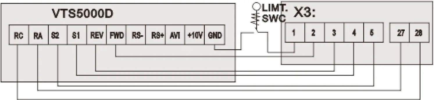 Use FWD/REV/S1/S2 inputs to set desired drive function (1=on,0=off)
| 0000 = STOP | |
| 1100 = START, 1ST SPEED | Value is P503 |
| 1110 = START, 2ND SPEED | Value is P503+P504 |
| 1111 = START, 3RD SPEED | Value is P503+P504+P505 |
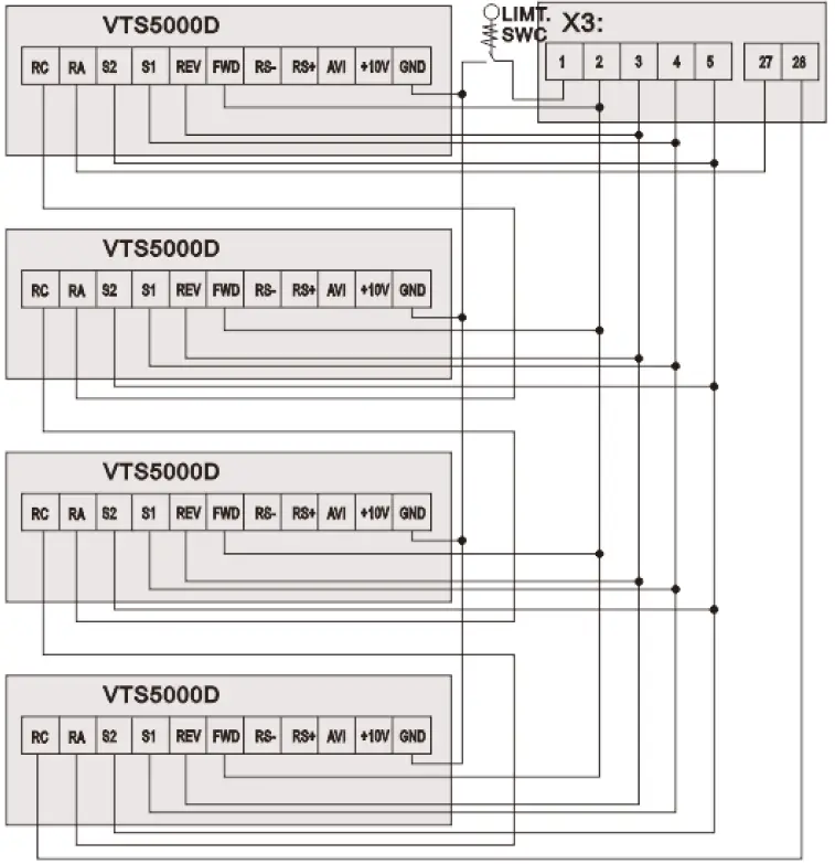
NOTE! If the AHU is equipped with more than 1 fan, follow Figure 2b for proper cabling.
 AHU WITH VTS CONTROLS TYPE: VS … CG ACX36 EVO … or VS … CG uPC …
Set additional parameters
| Parameter | Code | Value | Comments |
| Main frequency source X selection | P101 | 5 | 5: RS485 communication frequency setting |
| Start signal selection | F102 | 2 | 2:Communication(RS485) |
| Converter’s address in Modbus Network | P702 | 2 | Air-supply fan |
| 3 | Air-exhaust fan | ||
| 5 | Air-supply fan No.2 / redundant | ||
| 7 | Air-supply fan No.3 | ||
| 9 | Air-supply fan No.4 | ||
| 6 | Air-exhaust fan No.2/ redundant | ||
| 8 | Air-exhaust fan No.3 | ||
| 10 | Air-exhaust fan No.4 | ||
| Action of RS485 communication error | P703 | 2 | 0: No warning 1: Warning, display Co 2: Display Co and stop |
Communication parameters as below: Modbus RS-485, 9600 8N1,
Wire the communication terminal of the VTS5000D inverter according to the 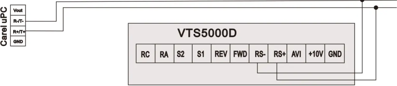 CAUTION: It is recommended to apply an automatic procedure for the converters’ configuration, which is available in advanced options of the HMI Advanced panel.
NOTE: To restore VTS5000D to default settings set P117 = 8 and switch off the power supply.


