LINOVISION IOT-R75W Industrial 5G Router User Guide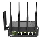
Welcome
Thank you for choosing Linovision R75 industrial cellular router.
This guide describes how to install the R75 and how to log in the Web GUI to configure the device. Once you complete the installation, refer to the Linovision R75 User Guide for instructions on how to perform configurations on the device.
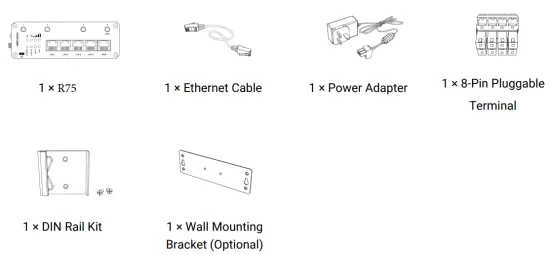
Packing List
Before you begin to install the R75 router, please check the package contents to verify that you have received the items below.
R75-5G Antennas: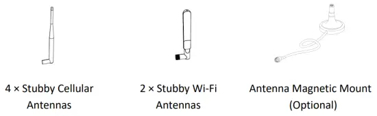
If any of the above items is missing or damaged, please contact your sales representative.
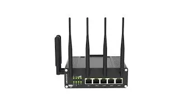
Hardware Introduction
Overview
A. Front Panel of R75-5G
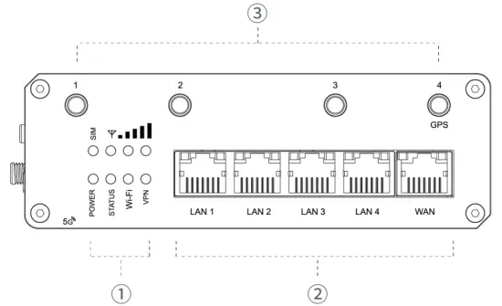
- LED Indicator Area
POWER: Power Indicator
SYSTEM: Status Indicator
Wi-Fi: Wi-Fi Indicator
VPN: VPN Indicator
SIM : SIM Status Indicator : Signal Strength Indicator
 - Ethernet Ports & Indicators
- Cellular Antenna Connectors (Connector 4 is for both GPS and cellular)
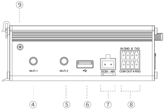
C. Left Side Panel
- Wi-Fi Antenna Connector 1
- Wi-Fi Antenna Connector 2
- USB Port (Reserved)
- Power Connector
- Serial Port & I/O Ports
- Grounding Stud
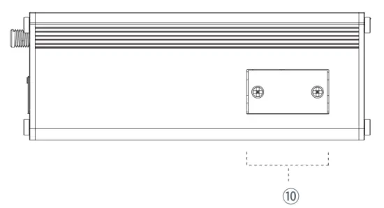
D. Right Side Panel
- SIM and Reset Button Holder
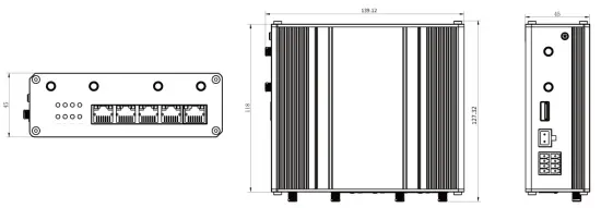
Dimensions (mm)
Connectors
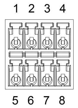
Serial Port&I/O Ports
| PIN | RS232 | RS485 | DI | DO | Description |
| 1 | — | — | IN | — | Digital Input |
| 2 | GND | — | GND | — | Ground |
| 3 | — | B | — | — | Data – |
| 4 | TXD | — | — | — | Transmit Data |
| 5 | — | — | — | COM | Common Ground |
| 6 | — | — | — | OUT | Digital Output |
| 7 | — | A | — | — | Data + |
| 8 | RXD | — | — | — | Receive Data |
Note: For -RS485 model, RXD—>A, TXD—>B.
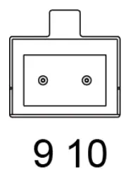
Power Connector
| PIN | Description | Wire Color |
| 9 | Positive | Red |
| 10 | Negative | Black |
LED Indicators
| LED | Indication | Status | Description |
| POWER | Power Status | Off | The power is switched off |
| On | The power is switched on | ||
| SYSTEM | System Status | Green Light | Static: Start-up |
| Blinking slowly: the system is running properly | |||
| Red Light | The system goes wrong | ||
| VPN | VPN Status | Off | VPN is disconnected |
| Green Light | VPN is connected | ||
| Wi-Fi | Wi-Fi Status | Off | Wi-Fi is disabled |
| Green Light | Static: Wi-Fi is enabled | ||
| Blinking slowly: sending or receiving data via Wi-Fi | |||
| SIM | SIM Card Status | Off | SIM1 or SIM2 is registering or fails to register (or there are no SIM cards inserted) |
| Green Light | Blinking slowly: SIM1 (as primary SIM) has been registered and is ready for dial-up | ||
| Blinking rapidly: SIM1(as primary SIM) has been registered and is dialing up now | |||
| Static: SIM1 (as primary SIM) has been registered and dialed up successfully | |||
| Orange Light | Blinking slowly: SIM2 (as primary SIM) has been registered and is ready for dial-up | ||
| Blinking rapidly: SIM2 (as primary SIM) has been registered and is dialing up now | |||
| Static: SIM2 (as primary SIM) has been registered and dialed up successfully | |||
| Signal Strength | Signal 1/2/3 | Off | No signal |
| Green Light | Static/Off/Off: weak signals with 1-10 ASU (please check if the antenna is installed correctly, or move the antenna to a suitable location to get better signal) | ||
| Static/Static/Off: normal signals with 11-20 ASU (average signal strength) | |||
| Static/Static/Static: strong signals with 21-31 ASU (signal is good) |
Reset Button
Reset button is under the SIM slots.
| Function | Description | |
| SYSTEM LED | Action | |
| Reset | Blinking | Press and hold the reset button for more than 5 seconds. |
| Static Green → Rapidly Blinking | Release the button and wait. | |
| Off → Blinking | The router is now reset to factory defaults. | |
Ethernet Port Indicator
| Indicator | Status | Description |
| Link Indicator (Orange) | On | Connected |
| Blinking | Transmitting data | |
| Off | Disconnected |
Hardware Installation
Environmental Requirements
- Power Input: 9-48 VDC (48 VDC is needed for PoE output)
- Power Consumption: ≤ 7.9W (In Non-PoE mode)
- Operating Temperature: -40°C to 70°C (-40°F -158°F)
- Relative Humidity: 0% to 95% (non-condensing) at 25°C/77°F
SIM Card/Micro SD Card Installation
R75 do not support hot-plug. Please cut off the power before insert or take off cards.
A. Unscrew the holder of the SIM card.”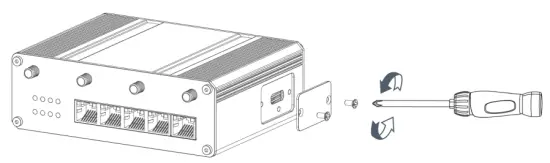
B. Insert the SIM card(s) into the device following the triangle location of SIM card(s).
C. Put SIM card into the slot and screw it up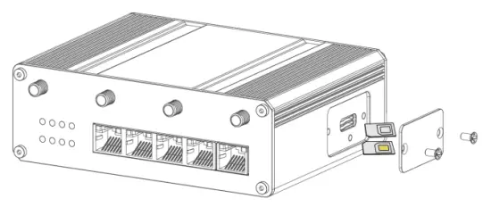
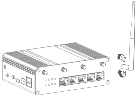
Antenna Installation
Rotate the antenna into the antenna connector accordingly.
The external antenna should be installed vertically always on a site with a good signal.
Router Installation
The router can be placed on a desktop or mounted to a wall or a DIN rail.
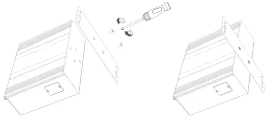
Wall Mounting (Measured in mm
Use 2 pcs of M3 × 6 flat head Phillips screws to fix the wall mounting kit to the router, and then use 2 pcs of M3 drywall screws to mount the router associated with the wall mounting kit on the wall.
Recommended torque for mounting is 1.0 N·m, and the maximum allowed is 1.2 N·m.
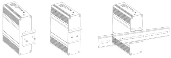
DIN Rail Mounting (Measured in mm)
Use 2 pcs of M3 × 6 flat head Phillips screws to fix the DIN rail to the router, and then hang the DIN rail on the mounting bracket. It is necessary to choose a standard bracket.
Recommended torque for mounting is 1.0 N·m, and the maximum allowed is 1.2 N·m.
Protective Grounding Installation
A. Remove the grounding nut.
B. Connect the grounding ring of the cabinet’s grounding wire onto the grounding stud and screw up the grounding nut.
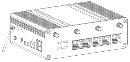
The router must be grounded when deployed. According to operating environment, the ground wires should be connected with grounding stud of router.
Log in the Web GUI of Router
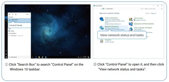
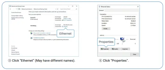
PC Configuration
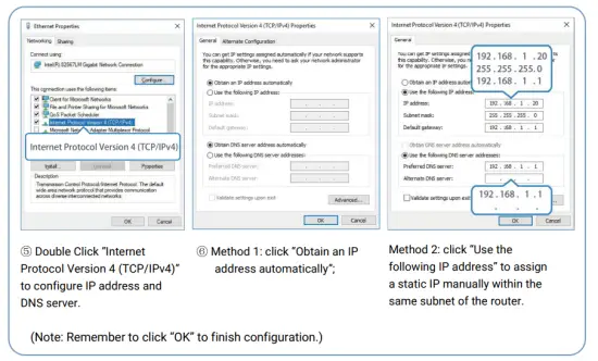
Please connect PC to any port among LAN1-LAN4 of R75 router. PC can obtain an IP address, or you can configure a static IP address manually. The following steps are based on Windows 10 operating system for your reference.
(Note: As remote access is disabled by default, you can’t access to the router’s Web GUI if you connect
PC to WAN port of the router. But it will function properly if you enable it on Web GUI.
Log in the Router
If this is the first time you configure the router, please use the default settings below:
IP Address: 192.168.1.1
Username: admin
Password: password
A. Start a Web browser on your PC (Chrome is recommended), type in the IP address, and press Enter on your keyboard.
B. Enter the username and password, click “Login”.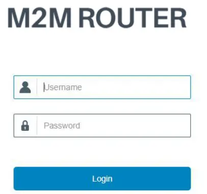
If you enter the username or password incorrectly more than 5 times, the login page will be locked for 10 minutes.
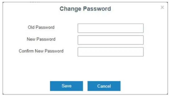
C. When you log in with the default username and password, you will be asked to modify the password. It’s suggested that you change the password for the sake of security. Click “Cancel” button if you want to modify it later.
D. After you log in the Web GUI, you can view system information and perform configuration on the router.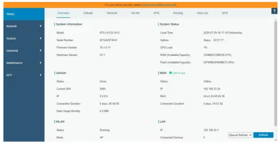
Network Configuration
This chapter explains how to connect R75 to network via WAN connection or cellular.
Ethernet WAN Configuration
A. Go to “Network > Interface > WAN” to configure WAN parameters. Take static IP configuration as an example. DHCP client and PPPoE type are optional according to your requirements.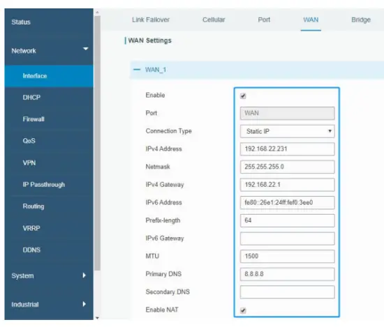
Click “Save & Apply” button to make the changes take effect.
B. Connect WAN port to another router or modem.
C. Log in R75 web GUI via WAN port IP address and go to “Status > Network” to check if status is “up”.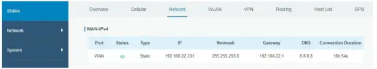
D. Go to “Network > Interface > Link Failover” to rise the WAN priority to 1.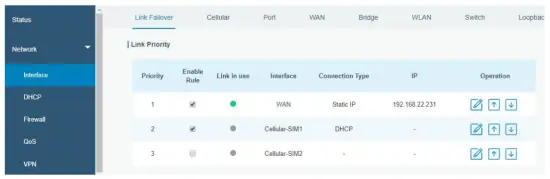
E. Open your preferred browser on PC, then type any available web address into address bar and see if it is able to visit Internet via R75 router.
Cellular Connection Configuration
Take inserting SIM card into SIM1 slot as an example; please refer to the following detailed operations.
A. Click “Network > Interface > Cellular > Cellular Setting” to configure the cellular info, like APN and network type.
B. Click “Save” and “Apply” for configuration to take effect.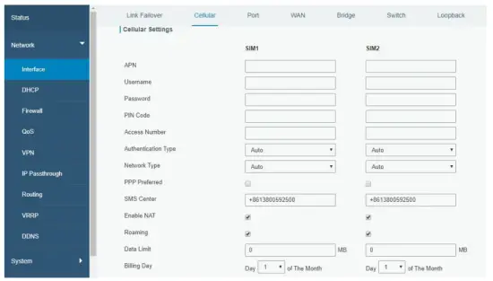
If you select “Auto”, the router will obtain ISP information from SIM card to set APN, Username, and Password automatically. This option will only be taken effect when the SIM card is issued from a well-known ISP.
C. Go to “Network > Interface > Link Failover” to enable SIM1 and rise link priority of SIM1.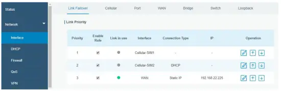
D. Click ![]() to configure ICMP ping detection information.
to configure ICMP ping detection information.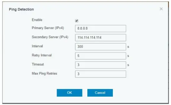
E. Click “Status > Cellular” to view the status of the cellular connection. If it shows “Connected”, it means SIM1 has dialed up successfully. On the other hand, you can check the status of SIM indicator. If it keeps on green light statically, it means SIM1 has dialed up successfully.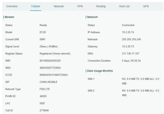
F. Open your preferred browser on PC, then type any available web address into address bar and see if it is able to visit Internet via R75 router.
Related Documents
This Start Guide only explains the installation of Linovision R75 router. For more functionality and advanced settings, please refer to the relevant documents as below.
| Document | Description |
| R75 Datasheet | Datasheet for R75 industrial cellular router. |
| R75 User Guide | Users could refer to the guide for instruction on how to log in the web GUI, and how to configure all the settings. |
The related documents are available on Linovision website: https://www.linovision.com/
Declaration of Conformity
R75 are in conformity with the essential requirements and other relevant provisions of the CE, FCC, and RoHS.

© 2007-2021 Linovision Co., Ltd.
All rights reserved.
All information in this guide is protected by copyright law. Whereby, no organization or individual shall copy or reproduce the whole or part of this user guide by any means without written authorization from Hangzhou Linovision Co., Ltd
Get Help
For assistance, please contact
Linovision support:
Email: [email protected]
Tel: 86-571-86708175
Revision History
| Date | Doc Version | Description |
| Aug. 4, 2020 | V 1.0 | Initial version |
| Nov. 20, 2020 | V 2.0 | Layout replace |


