![]()
99 Washington Street
Melrose, MA 02176
Phone 781-665-1400
Toll Free 1-800-517-8431
Visit us at www.TestEquipmentDepot.com
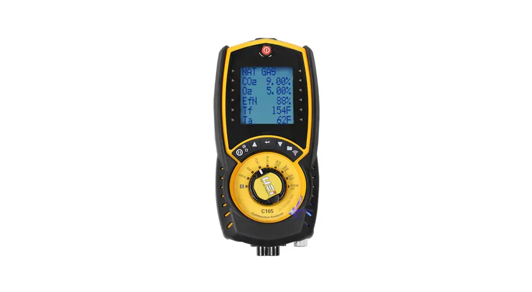
C165 QUICK START GUIDE
GETTING STARTED
Press ![]() “Power” in the fresh air and allow to countdown for Fresh Air purge.
“Power” in the fresh air and allow to countdown for Fresh Air purge.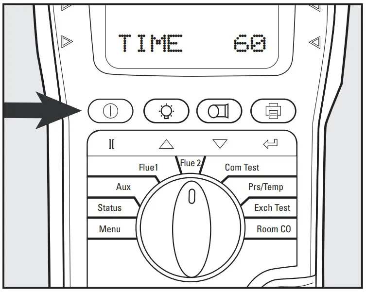
Rotate selector dial to Flue 1. In fresh air, the O2 reading should be 20.9% ±0.3%.
Rotate selector dial to Flue 2. In fresh air, the CO reading should be zero (0).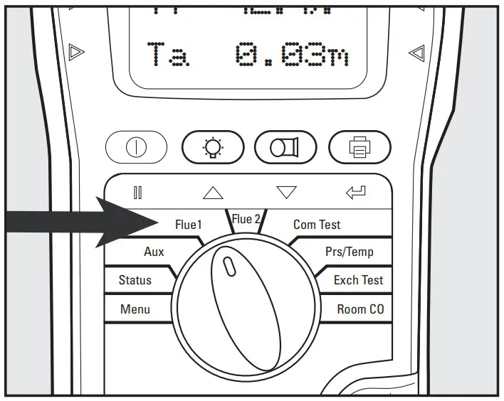
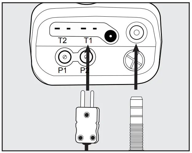
Connect the flue probe thermocouple connector to T1.
Connect flue probe to the water trap.
Connect the optional probe to T2.
BASIC CO/COMBUSTION ANALYSIS
Insert Flue probe into the stack. Adjust cone so the end of the probe is approximately at the center of the stack.
NOTE: You will have to drill a hole at least 3/8″. Use appropriate sealing method after testing.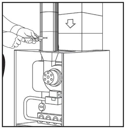 Rotate selector dial to Flue 1 for CO2, O2, Gross efficiency, Flue temperature, Inlet temperature. Fuel type can be changed via MENU or STATUS setting
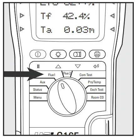 Rotate selector dial to Flue 2 for CO (ppm), Losses calculated, Excess air %, pressure reading Fuel type can be changed via
MENU or STATUS setting. Make any adjustments as needed for proper combustion and wait for the analyzer to display changes in readings. (Repeat as necessary).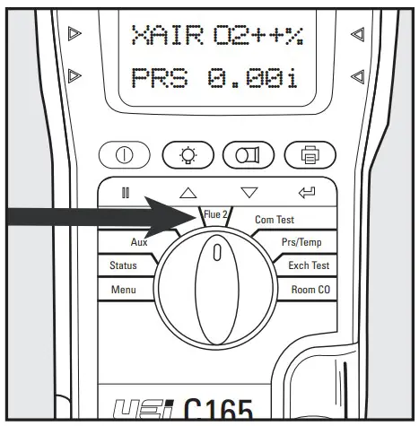
Once complete, remove the probe from the stack, allow the analyzer to purge in fresh air until CO sensor readings return to ZERO (0) and O2 readings reading return to 0% to 21%. Continue to the next test or power analyzer off by pressing On/Off, if finished.
NOTE: Print and store functions may be used at any time during testing.
DIFFERENTIAL TEMPERATURE TEST
Rotate the selector dial to
Pressure/Temperature.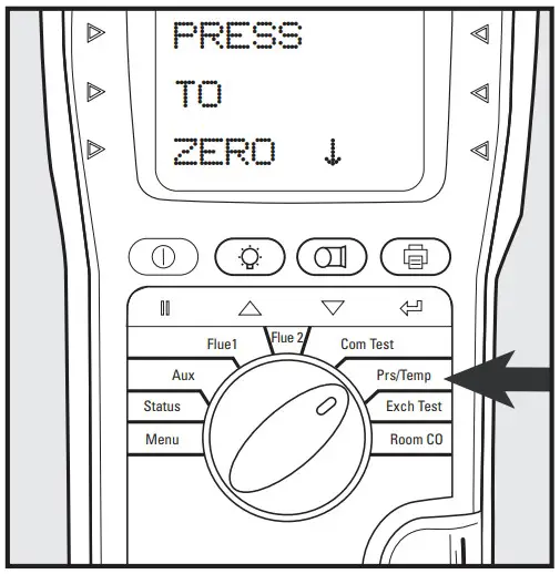 Press
Press ![]() “Pump” to ZERO (0) pressure sensor.
“Pump” to ZERO (0) pressure sensor.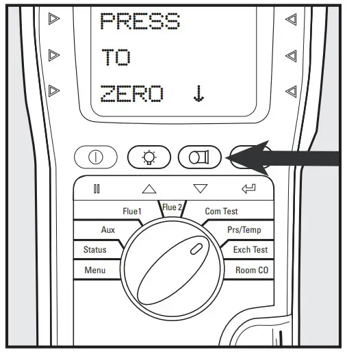 Connect the probe to T1. Connect the probe to T2. Compatible with any K-Type thermocouple probe or clamp.
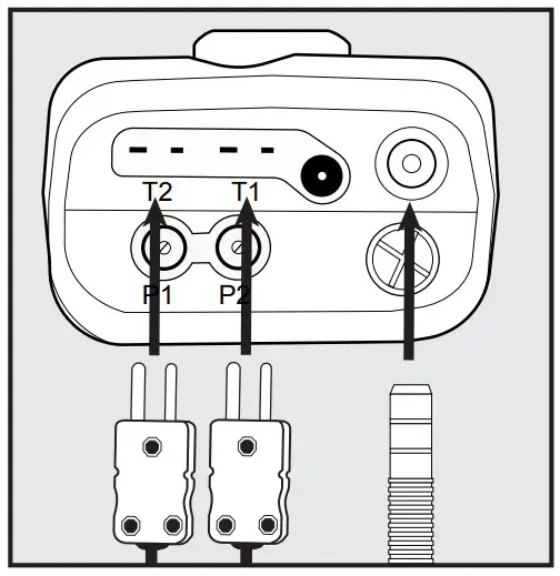 Connect thermocouples in test location to start testing
Observe T1, T2, and differential (Delta T).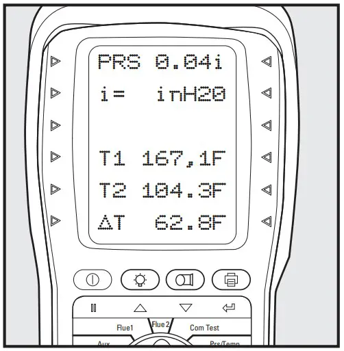
Press ![]() “Print” to print results. Press and Hold results.
“Print” to print results. Press and Hold results.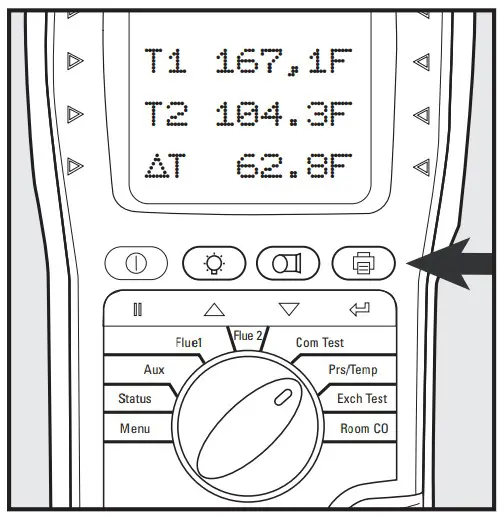
DRAFT & STATIC PRESSURE TEST
Rotate the selector dial to Pressure/Temperature.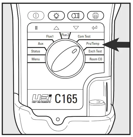 Press
Press ![]() “Pump” to ZERO (0) pressure sensor.
“Pump” to ZERO (0) pressure sensor.
Connect a true draft hose to PI. Connect to P2 for differential. Place probe tip in the stack to measure draft.
Connect static pressure hose to measure differential pressure.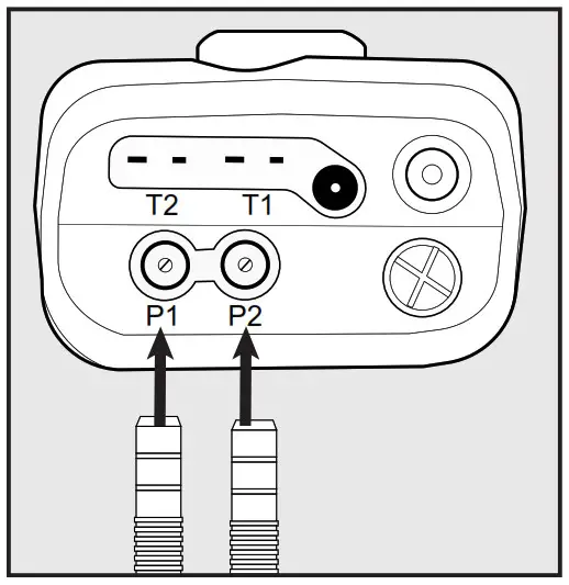
Place true draft probe tip in the flue to measure draft.
You can also use the combustion probe for measuring pressure.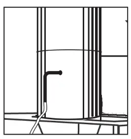
Press ![]() “Print” to print results.
“Print” to print results.
Press and Hold ![]() results.
results.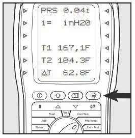
HEAT EXCHANGER TEST
There are many methods to test heat exchanger integrity. One of these is to observe Excess Air, O2, AND CO readings both before and after the blower turn on. If the heat exchanger is sealed your O2 and CO readings should remain fairly stable. A breach in the heat exchanger may allow fresh air to be forced into the flue after the blower turns on due to a pressure increase in the plenum. The result may be a rise in the measured O2 in the stack gas and an increase in the Excess Air. In some sealed systems the fresh air drawn in the breach may reduce the combustion available leading to an increase in the CO reading. If either of these situations is present it is probable that there is a problem with the Heat Exchanger which may require additional testing and inspection.
NOTE: Many cracks are invisible to borescopes or the naked eye and only open or separate from pressure or temperature during operation.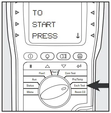 Confirm the Fuel Type. Scroll
 ![]() or
or ![]() switch a different fuel type.
switch a different fuel type.
Press ![]() to select fuel type.
to select fuel type.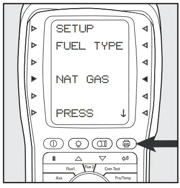
NOTE: The analyzer will perform a fresh air purge if it did not perform one on startup. Otherwise, it will skip past the zeroing step to the Blower Offscreen. See manual for details. ![]() Press to continue.
Press to continue.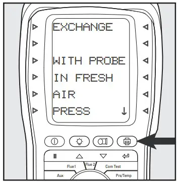 Ensure the analyzer is in fresh air during the countdown. The screen will automatically advance when complete.
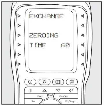
Call for heat.
Observe and wait for O2 readings to stabilize. after the blower turns on, press the button to start the Post-Blower test.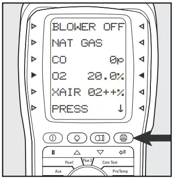 The analyzer will wait for 60 seconds and then record the
Post-Blower values for CO,02, and Excess Air.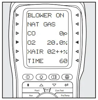
Test results will automatic-cally be stored to exchange reports. The report includes both Pre and post Blower test segments.
Press ![]() to start printing. See the REPORTS section in this guide.
to start printing. See the REPORTS section in this guide.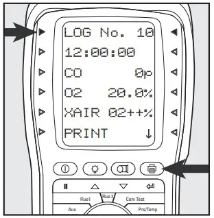
CO ROOM TEST
Great for checking ambient CO and back drafting situations
No probes or hose connections are required for this test.
Rotate selector dial to ROOM CO. ![]() Press “Print” to start the GENERAL test.
Press “Print” to start the GENERAL test.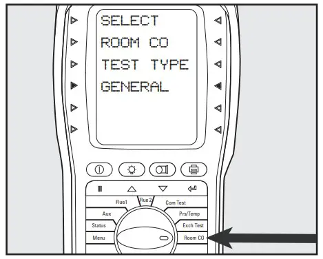
Press ![]() Flue 2 to start the test.
Flue 2 to start the test.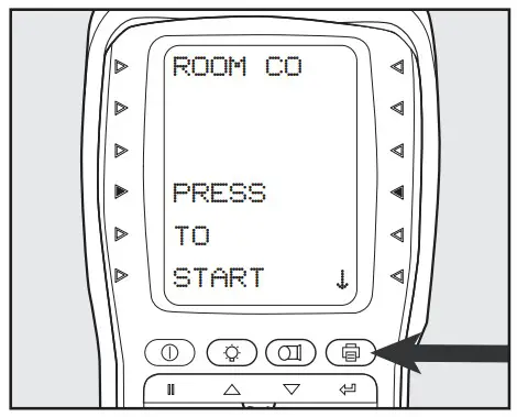
CO readings will be logged every 2 minutes for a 30-minute time span.
Readings will be stored once the 30-minute test is completed.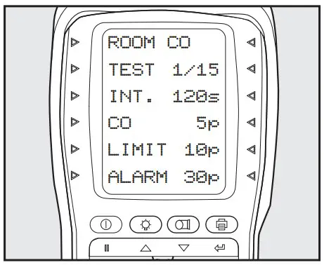
Press ![]() to print results.
to print results.
Test results will automatically be stored in ROOM CO reports. See the REPORTS section in this guide.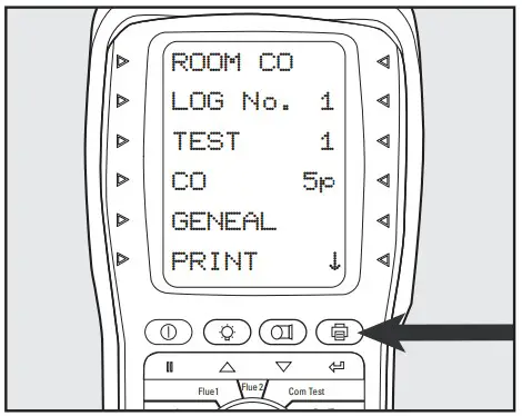
AUX SETTING
Programmable Auxiliary screen allows for Tech selectable test parameters to be chosen.
Rotate selector dial to Menu. Scroll or ![]() to
to ![]() Screen. Press “Print” to select.
Screen. Press “Print” to select.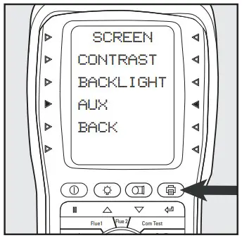 Scroll
 ![]() or
or![]() customize any Line. Press
customize any Line. Press ![]() to select. [Line 5 shown]
to select. [Line 5 shown]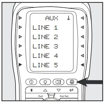 Scroll
![]() or
or![]() select the parameter for this line. Press
select the parameter for this line. Press ![]() to select. [Pressure shown]
to select. [Pressure shown]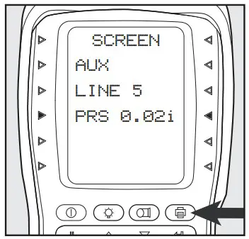
Rotate selector dial to AUX to view.
Custom selections will now display in AUX mode.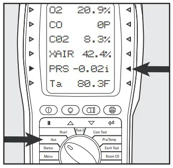 REPORTS: PRINTING & VIEWING
Print and Log easily from the following test screens: Aux, Flue 1, Flue 2, Commission Test, Pressure/Temperature, Exchange Test, and Room CO
Press ![]() “Print” to start printouts of results from any test screen. Press
“Print” to start printouts of results from any test screen. Press ![]() during printing to cancel.
during printing to cancel.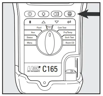 Press and hold to
![]() log current readings. Align printer above Analyzer.
log current readings. Align printer above Analyzer.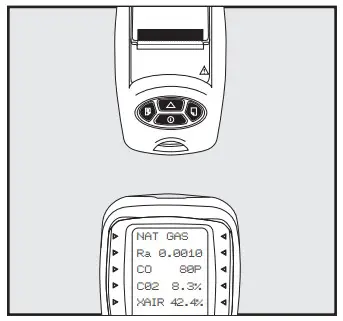 To view test results, rotate the dial to Menu. Scroll
 ![]() or
or![]() to Report Press
to Report Press![]() to select.
to select.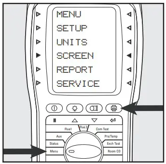
Scroll ![]() or
or ![]() type of test wanted. Press to select. [Exchange shown] Press
type of test wanted. Press to select. [Exchange shown] Press ![]() to select View.
to select View.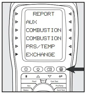 Press
Press![]() to select report log number. When indicator lights blink, use
to select report log number. When indicator lights blink, use ![]() or
or ![]() scroll through logged reports. Press
scroll through logged reports. Press ![]() to view a selected report log.
to view a selected report log.
HIGH CO ALERT
At 1000 ppm CO the screen will display HIGH CO and an indicator light will flash and the analyzer will beep several times. Above 2000 ppm the purge pump starts.
MAIN MENU | SUBMENU | OPTIONS / COMMENTS |
| SETUP | LANGUAGE | English |
| SET TIME | HH:MM: SS format e.g. 7 am = 07:00:00, 7 pm =19:00:00 | |
| SET DATE | MM/DD/YY format | |
| PRINTER | KM IRP KANE IRP•2 WIRELESS lif installed) SERIAL | |
| PASSKEY | 1111(wait 5 secs after entering the last digit) | |
| BACK | ||
| UNITS | FUEL TYPE | NAT GAS, TOWN GAS, COKE GAS, PROPANE, BUTANE, LPG, LIGHT OIL, BIO-OIL. WOOD PELLETS, BIOGAS, USER 1 to 5 |
| FUEL ORIGIN | UK, FRANCE, SPAIN, N AMERICA, BELGIUM, NETHERLAND | |
| EFFICIENCY | GROSS. NET. GROSS COND. NET COND | |
| PRESSURE | FILTER: OFF = normal response. ON = slower (damped) response | |
| RESOLUTION: LOW = e.g. 0.00i inH20 resolution. HIGH = displays roan extra decimal place | ||
| UNITS: mbar, Pa, PSI, mmHg, hPa, inH20, mmH20, kPa, psi | ||
| TIME: Test units not available in North American market | ||
| BACK: | ||
| GAS | PPm. PPal(n), mg/m3, mg/m3(n), mg/kWh, mg/kWh(n) | |
| TEMP | C. F | |
| 02 REF | Up/down to set value (3% default) | |
| NOx CALC | Up/down to set value 15% default) | |
| BACK | ||
| SCREEN | CONTRAST | The factory setting is 14 |
| BACKLIGHT | 0 to 300 secs | |
| AUX | Enables users to customize the parameters on the AUX display: LINE 1, LINE 2, LINE 3. LINE 4, LINE 5, LINE 6, BACK | |
| BACK | ||
| REPORT | AUX | Stored AUX tests VIEW, DEL ALL, BACK |
| COMBUSTION | Stored combustion tests: VIEW, DEL ALL, BACK | |
| COMMISSION | Stored commission tests: VIEW, DEL ALL, BACK | |
| PRS/TEMP | Stored pressure tests: VIEW, DEL ALL, BACK | |
| EXCH | Stored exchange tests: VIEW, DEL ALL, BACK | |
| ROOM CO | Stored room CO tests: VIEW, DEL ALL, BACK | |
| HEADER | LINE 1 LINE 2 BACK | |
| BACK | ||
| SERVICE | CODE | Password protected for authorized service agents only. Leave set to 000000. |
L466 0119Test Equipment Depot – 800.517.8431 – 99 Washington Street Melrose, MA 02176
TestEquipmentDepot.com
Copyright © 2019 Kane USA, Inc. All Rights Reserved


