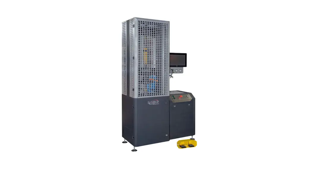
![]() MS1000+ Test Bench
MS1000+ Test Bench
User Manual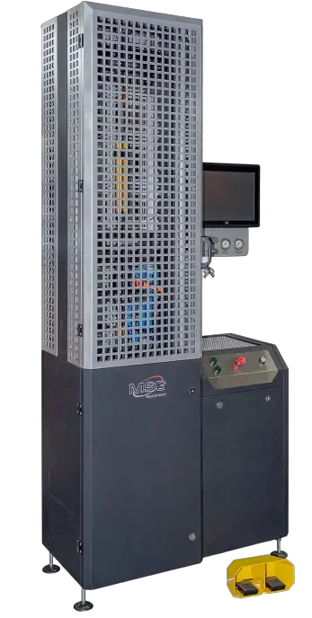 MS1000+
TEST BENCH FOR DIAGNOSTICS OF SHOCK ABSORBERS
USER MANUAL
INTRODUCTION
Thank you for choosing the product by ТМ MSG equipment.
The actual User Manual contains information on application, technical characteristics, package contents, design of MS1000+ and all the important details regarding its operation.
It is strongly recommended to learn carefully the actual User Manual before putting MS1000+ (hereinafter, “the test bench”) in operation, take special training at the equipment manufacturing facility if necessary.
Due to the continual improvement of the test bench structure and configuration as well as firmware upgrade, some changes might not be reflected in this User Manual. The test bench firmware will require update. Later, firmware support and maintenance can be discontinued without prior notice to users.![]() WARNING! The actual user manual does not contain information on how to diagnose shock absorbers with the test bench. Follow the link MS1000+ MANUAL FOR DIAGNOSING SHOCK ABSORBERS to find this information.
WARNING! The actual user manual does not contain information on how to diagnose shock absorbers with the test bench. Follow the link MS1000+ MANUAL FOR DIAGNOSING SHOCK ABSORBERS to find this information.
PURPOSE
The test bench is designed to assess technical condition of shock absorbers in passenger cars through taking their force-displacement and force-velocity characteristics.
The test bench for shock absorbers is used to do the following:
- establish whether a faulty unit should be repaired or replaced;
- check on the quality of repair;
- assess the conformity of shock absorber performance to its technical specifications;
- conduct prolonged tests.
A shock absorber can be tested on the test bench both in manual and automatic modes.
The test bench functionality enables the following:
- test all types of passenger car shock absorbers having dumping force up to 1000 kg and equipped with different mounting mechanisms;
- save test-results;
- compare test results with reference data (before and after repair);
- generate test reports and print them on an external printer.
TECHNICAL CHARACTERSISTICS
Main features | ||
| Supply voltage, V | 400 | |
| Supply type | Three-phase | |
| Drive power, kW | 3.7 | |
| Dimensions (L×W×H), mm | 970×480×2500 | |
| Weight, kg | 350 | |
| Clamp control | Pneumatic | |
| Test bench pneumatic system power pressure, bar | 6 | |
| Operating modes | Manual/Automatic | |
Shock absorber testing | ||
| Size of tested shock absorber | maximum, mm | 780 |
| minimum, mm | 250 | |
| Height adjustment of shock absorber fixing | Manual | |
| Shock absorber shaft stroke, mm | Adjustable, from 50 to 150 | |
| Shock absorber shaft stroke adjustment | Manual | |
| Bound/rebound maximum load, kg | 1000 | |
| Frequency of shock absorber vibrations | Maximum, min-1 | 180 |
| Minimum, min-1 | 10 | |
| Shock absorber piston speed (at 50 mm travel) | Maximum, m/s | 0.477 |
| Minimum, m/s | 0.026 | |
| Shock absorber temperature measuring | Yes | |
Additional features | |
| Data printout | Yes |
| Software update | Yes |
| Connection to the Internet | Wi-Fi (802.11 a/b/g/ac) |
| Connection of external devices | 2 x USB 2.0 |
EQUIPMENT SET
The equipment set includes:
| Item name | Number of pcs |
| Test bench MS1000+ | 1 |
| Pneumatic clamp foot control | 1 |
| Handle for fixing pneumatic clamp lock nuts | 2 |
| 2-piece set of changeable fittings for shock absorber | 3 |
| Universal prism for fixing shock absorbers with rod end | 2 |
| Universal prism for fixing shock absorbers with uncalibrated holes (for shock absorbers with irregular shafts) | 1 |
| Temperature sensor strip | 1 |
| Vibration-absorbing pads | 4 |
| Wi-Fi module | 1 |
| Stylus | 1 |
| Bench door keys | 2 |
| Socket 400V | 1 |
| User Manual (card with QR code) | 1 |
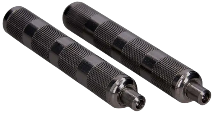 Figure 1. Handles for fixing pneumatic clamp lock nuts
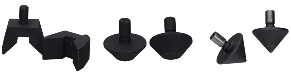 Figure 2. Shock absorber changeable fittings for lower pneumatic clamp (for various types of shock absorber mounting mechanisms)
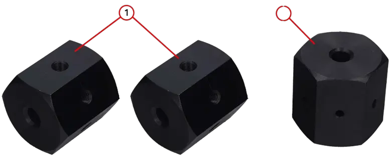 Figure 3. Universal prisms for fixing shock absorbers:
- universal prisms for fixing shock absorbers with rod ends;
- universal prism for fixing shock absorbers with uncalibrated holes (for shock absorbers with irregular shafts). The prism is a rough work piece which is to be processed (through tapping) into a special shock absorber lock.
TEST BENCH DESCRIPTION
The test bench consists of the following main components (Fig.4): 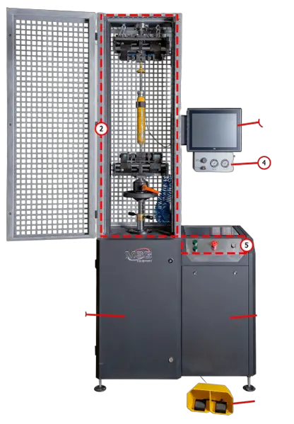 Figure 4. Main components of the test bench
- mechanical unit;
- test compartment where a shock absorber is located during diagnostics;
- display for diagnostic data output and test bench control;
- shock absorber nitrogen filling block;
- control panel with ON/OFF switch, emergency button, and pneumatic clamp control buttons;
- electrical unit;
- pneumatic clamp foot control performing the same functions as the respective buttons on the control panel.
All the operations with the tested shock absorber are carried out in the test compartment (Fig.5) equipped as follows: 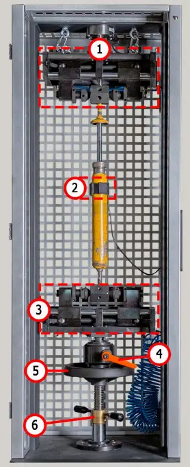 Figure 5. Test compartment
- upper pneumatic clamp;
- temperature sensor and strip for fastening it to a shock absorber;
- lower pneumatic clamp;
- lower clamp lock;
- rotation wheel for lower clamp height adjustment;
- retainer for lower clamp height adjustment.
A shock absorber is secured inside the test compartment with pneumatic clamps consisting of the components shown in Fig. 6 and 7.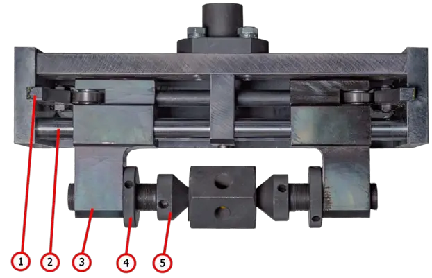 Figure 6. Components of upper pneumatic clamp:
- linear cam;
- guide slide block;
- slide block;
- lock nut;
- push rod.
The lower pneumatic clamp is equipped with changeable fittings (Fig.7) for securing shock absorbers with different mounting mechanisms.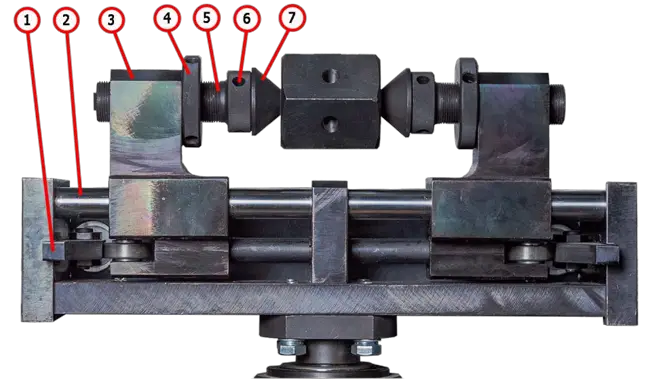 Figure 7. Components of lower pneumatic clamp:
- linear cam;
- guide slide block;
- slide block;
- lock nut;
- push rod;
- socket set screw;
- mechanism for shock absorber fixing.
Control panel buttons (Fig.8): 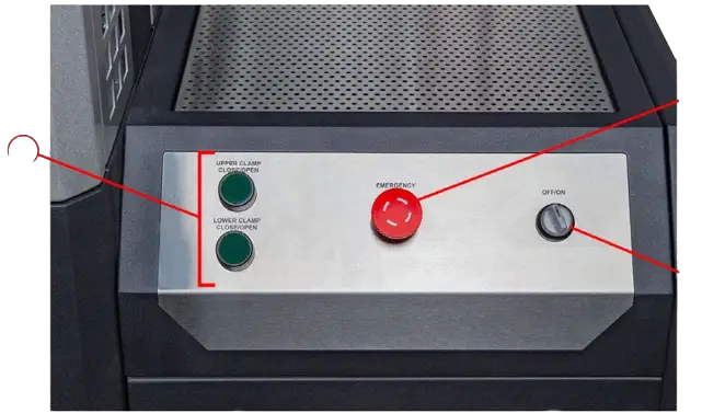 Figure 8. Control panel
- pneumatic clamp control buttons;
- EMERGENCY STOP button for emergency power cutoff;
- OFF/ON switch for test bench activation/deactivation. OFF/ON switch is inoperative when EMERGENCY STOP button is pressed.
The rear panel of the screen (Fig.9) contains the following: one LAN network connector for connection of the test bench to the Ethernet, two USB ports that can be used for connection of either a Wi-Fi adapter or external printer.  Figure 9. LAN and USB ports
Shock absorber nitrogen filling block consists of the following components (Fig.10):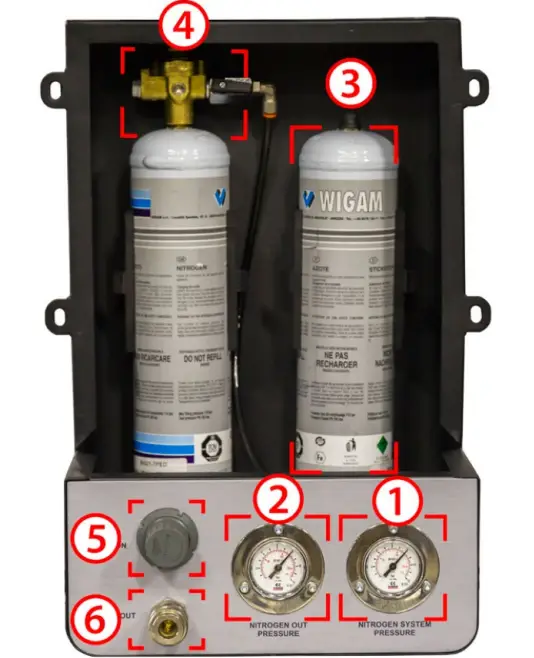 Figure 10. Components of nitrogen filling block:
- cylinder nitrogen pressure indicator;
- supply line pressure indicator
- nitrogen cylinders;
- gear;
- filling coupling nitrogen pressure control;
- filling coupling.
![]() WARNING! Cylinders with nitrogen and gear are not included in the equipment set.
WARNING! Cylinders with nitrogen and gear are not included in the equipment set.
In the bottom of the test bench rear panel there is a port for a compressed air supply hose (Fig.11, n.1) and power cord (Fig.11, n.2).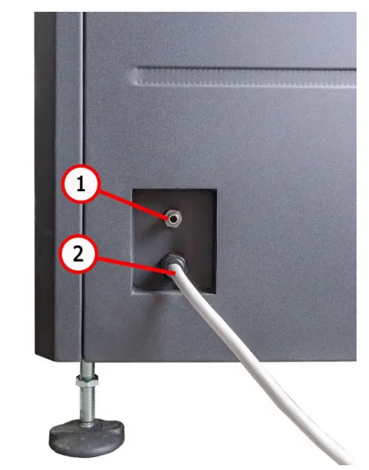 Figure 11. Port for connection of supply hose for compressed air
Shock absorber stroke adjustment along with some other maintenance operations are carried out in the mechanical unit of the test bench (Fig.12). The unit includes the following components:
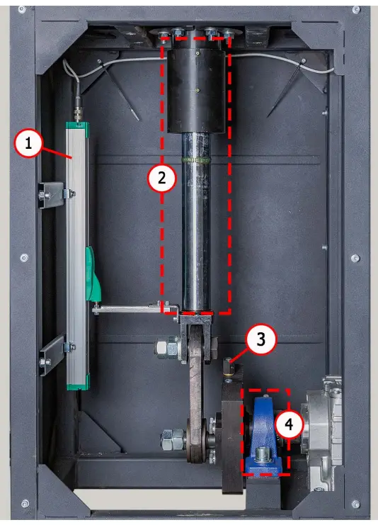
Figure 12. Mechanical unit
- position sensor;
- puller shaft;
- puller stroke adjustment mechanism;
- bearing.
APPROPRIATE USE
- The bench is used only for its intended purpose (see sect. 1).
- In the test area, it is prohibited to carry out any repair work on the shock absorber. This may lead to the breakdown of the bench.
- The shock absorber mounts securely in the pneumatic clamp. Do not allow any backlash between the shock absorber and pneumatic clamps. This will result in unreliable diagnostic data and a breakdown of the bench.
- It is prohibited to test a knowingly defective shock absorber and shock absorber with a spring.
- The bench shutdown should be performed through the interface of the service program, by clicking on the «Turn off the bench». After the monitor goes out, you can turn the «ON/OFF» button into the «OFF» position.
- Use the button «EMERGENCY STOP» only if necessary to stop the diagnostic process in an emergency.
- The touch screen saving uses the stylus (supplied as a set).
- The bench operating is prohibited in a defective condition and not connected to the ground.
- To avoid damage or failure of the bench, it is not allowed to make changes to the bench at one’s discretion. The bench cannot change by anyone other than the official manufacturer.
- Computer equipment and software use not designed to work with this bench voids warranty obligations (even if the software and equipment were subsequently deleted). Only the original MSG equipment software can be installed on this hardware.
- In the case of a breakdown in the operation of the bench, it should be stopped further and contact the manufacturer or the sales representative.
5.1. Safety regulations
- Only trained and authorized personnel is qualified to operate certain test bench types.
- It is strictly prohibited to activate the test bench when the doors of mechanical and electrical units are open. DO NOT open the doors before the expiry of 10 minutes after power off.
- Avoid dropping a shock absorber during its mounting/dismounting on the test bench.
- Keep your work space clean, well-illuminated, and spacious.
- Before testing, make sure the test bench is earthed and in good order. Otherwise the operation of the test bench is strictly forbidden.
- Disconnect the test bench from the power supply before starting any maintenance work.
5.2. Test bench mounting and setup
The test bench is delivered in packaging. Unpack the test bench and make sure it has no damages. Packaging materials are fully recyclable and should be wasted separately from domestic garbage. Position the test bench upright (use a leveling gauge) on the level floor. When moving the test bench, do not hold it by its movable or perforated parts. Put vibration-absorbing pads under the test bench legs.
Keep the distance of at least 0.5 meters between the test bench and the room walls or any other objects. The test bench ensures safe operation in the temperature range between +10 °С and +40 °С and relative humidity of 10-90% (without water condensation).
Before launching the test bench, connect it as follows:
– to 400V power supply line;
– to compressed air source.
TEST BENCH MAINTENANCE
Test bench is intended for long-lasting operation under twenty-four-hour schedule. However, for trouble-free enduring operation it is essential to inspect the test bench and observe preventive measures described below with recommended intervals. Inspection and preventive measures should be carried out by a qualified specialist.
Special attention should be paid to the following aspects of daily inspection:
- Appropriate operation of the motor (no unusual sounds, vibration, etc.).
- Appropriate ambient conditions for the test bench use (temperature, humidity, air pollution, vibration, etc.)
- Correspondence of supply voltage range to the test bench operation requirements. Weekly inspection of the test bench must include the following:
- Visual inspection of the bearing unit and puller shaft for traces of oil leaks.
- Check the moving parts of the upper and lower pneumatic clamps for sufficient lubrication.
![]() WARNING! Improper fixing of shock absorbers in pneumatic clamps is the most common cause of the test bench malfunction.
WARNING! Improper fixing of shock absorbers in pneumatic clamps is the most common cause of the test bench malfunction.
6.1. Pneumatic clamps oiling
Once a month check the lubrication of wear surfaces of linear cams (n.1, Fig. 6, 7) and glide slide blocks (n.2, Fig. 6, 7). Litol-24 is a commonly used grease. Other lithium-based greases are also usable.
Remove visible residue of old grease with a waste cloth before oiling pneumatic clamps. Move the clamps several times.
6.2. Bearing unit oiling
As the lubricating grease picks up dirt and loses its qualities with time, it should be refreshed every once in a while. The intervals at which the lubrication should be replaced or refreshed depend on the severity of use. However, the maximum interval shouldn’t exceed two years. During the first two times, lubrication can be refreshed. Subsequently, it must be replaced. Litol-24 is a commonly used lubricant. Other lithium-based greases are also usable.
To replenish the lubricating oil, use the nipple on the bearing unit (Fig.13) and a special syringe. 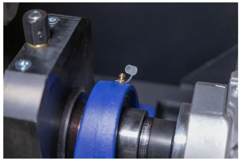
Figure 13. Nipple on the bearing unit
Follow the instruction below to oil the bearing unit:
- Disconnect the test bench form a supply line and wait for 10 minutes.
- Open the door of the mechanical unit.
- Remove the cap from the nipple, having it and the adjoining surfaces previously cleaned from dirt and dust.
- Use a special syringe to inject grease into the nipple. Continue to pump until you see grease squeezing out from the bearing.
- Upon finishing, remove the remaining grease with a cleaning cloth.
6.3. Puller shaft oiling
The lubricant type as well as grease replenishment and changing schedule are similar to the ones used for bearing unit maintenance (Section 6.1).
Follow the instruction below to oil the puller shaft:
- Disconnect the test bench form a supply line and wait for 10 minutes.
- Open the door of the mechanical unit.
- Clean the grease nipples (Fig.14) and adjoining surfaces from dust and dirt.
- Screw off one of the grease nipples.
- Use a special syringe to inject grease into the nipple. Continue to pump until you see grease squeezing out from the bearing.
- Upon finishing, remove the remaining grease with a cleaning cloth. Screw in the grease nipple
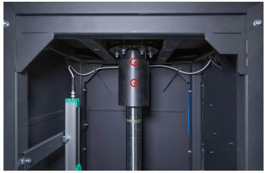 Figure14. Grease nipples on the puller shaft.
6.4 Gear motor inspection and maintenance
Perform the following maintenance procedures:
Every 500 hours of work or every month:
- Inspect the gear motor visually for possible oil leakage.
- Remove dust with a vacuum cleaner – the layer of dust accumulated on the gear motor cannot exceed 5mm thick.
Every 5 years:
Replace synthetic oil.
6.5 Cleaning and care
Use soft tissues or waste cloth to clean the test bench surfaces. Clean the touch screen with a special fibrous tissue and spray for display screens. Do not use any abrasive materials or solvents to avoid damage to the screen or corrosion.
TROUBLESHOOTING GUIDE
Below you will find the table with the possible problems and the solutions on their elimination.
| Problem | Causes | Solutions |
| 1. When you switch the test bench on, a three- pole circuit-breaker is actuated. | Test bench wiring is damaged | Contact sales representative |
| Too much dust inside the test bench | Clean the test bench | |
| 2. Unrealistic dynamogram indication. | Loose lock nut of force sensor fixation (pressure sensor) | Check force sensor fixation. Adjust if necessary |
| Loose fixation of position sensor | Check position sensor fixation. Adjust if necessary | |
| 3. Excessive steady noise emanates from electrical unit in the process of test bench operation. | Damage of gear motor bearings | Replace bearings |
| Foreign particles in oil | Check oil quality. Change oil if necessary | |
| 4. Motor is on – a gear input shaft rotates, while an output shaft does not | No engagement in gear | Contact sales representative |
| 5. Oil leak through gear cover. | Loss of tightness of rubber gasket under gear cover | Tighten bolts of gear cover fitting. If leakage continues, turn to sales representative |
| 6. Test bench diagnostic program load failure. | Test bench operating system failure | Contact sales representative |
| 7. Pneumatic clamps are out of work. | No pressure in pneumatic line | Check connection of compressed air supply |
| Condensed water in filter-dryer of air preparation unit | Remove filter-dryer plug and drain condensed water into prepared container |
| 8. Asynchronous operation of left and right pneumatic clamp pullers. | Different speed of pneumatic cylinders filling | Adjust speed of filling by air exhaust and air supply throttles |
| 9. Test mode activation failure. | EMERGENCY button on control panel is stuck | Check EMERGENCY button – it must be in neutral position |
| 10. Test turnaround failure. | Loose fixation of position sensor | Check position sensor fixation. Adjust if necessary |
| 11. Motor doesn’t start. | Short circuit of either cable or motor windings to ground | Clear a fault. Restart test bench |
| Low power supply voltage | Make sure there are no high- power consumers of high starting current nearby the test bench | |
| 12. Excessive vibration in the process of shock absorber diagnostics. | Poor fixing of shock absorber in pneumatic clamp | Check fixing: lock nuts of pneumatic clamps should be safely tightened |
| One of the two bearings in upper/lower pneumatic clamp is faulty | Check bearing inner and outer races for integrity. Replace bearing in case of deformation | |
| 13. Test bench is out of operation | No power supply | Check 400V power supply |
| Automatic cutout is off | Check automatic cutout | |
| Test bench power supply unit failure | Contact sales representative | |
| 14. No display respond to operator’s touch. | Touch screen is damaged | Contact sales representative |
| 15. Test bench operating system load failure. | Test bench operating system failure | Contact sales representative |
EQUIPMENT DISPOSAL
European Directive 2202/96/EC [WEEE (Waste Electrical and electronic Equipment)] applies to the Test Bench disposal.
Obsolete electronic equipment and electric appliances, including cables, fittings and batteries should be wasted separately from domestic garbage.
Use existing collection and recycling systems for waste disposal.
Proper waste disposal saves environment and personal health.
MSG equipment
HEADQUARTERS AND PRODUCTION
18 Biolohichna st.,
61030 Kharkiv
Ukraine
+38 057 728 49 64
+38 063 745 19 68![]() E-mail: [email protected]
E-mail: [email protected]
Website: servicems.eu
REPRESENTATIVE OFFICE IN POLAND
STS Sp. z o.o.
ul. Modlińska, 209,
Warszawa 03-120
+48 833 13 19 70
+48 886 89 30 56![]() E-mail: [email protected]
E-mail: [email protected]
Website: msgequipment.pl
TECHNICAL SUPPORT
+38 067 434 42 94![]() E-mail: [email protected]
E-mail: [email protected]![]()
![]()


