![]()
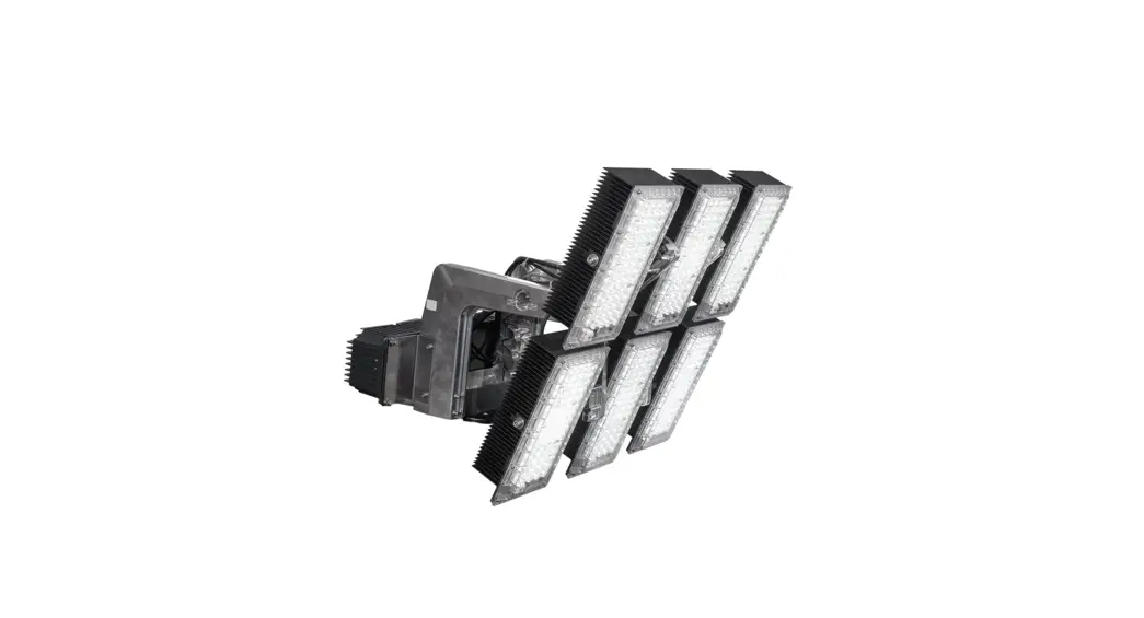
Eco blast 3 LED Solution for Sports Lightning
Instruction Manual
INSTALLATION INSTRUCTIONS

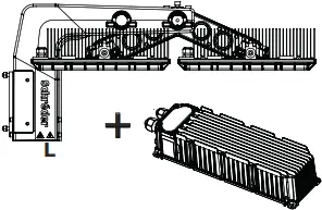
PRODUCT OVERVIEW
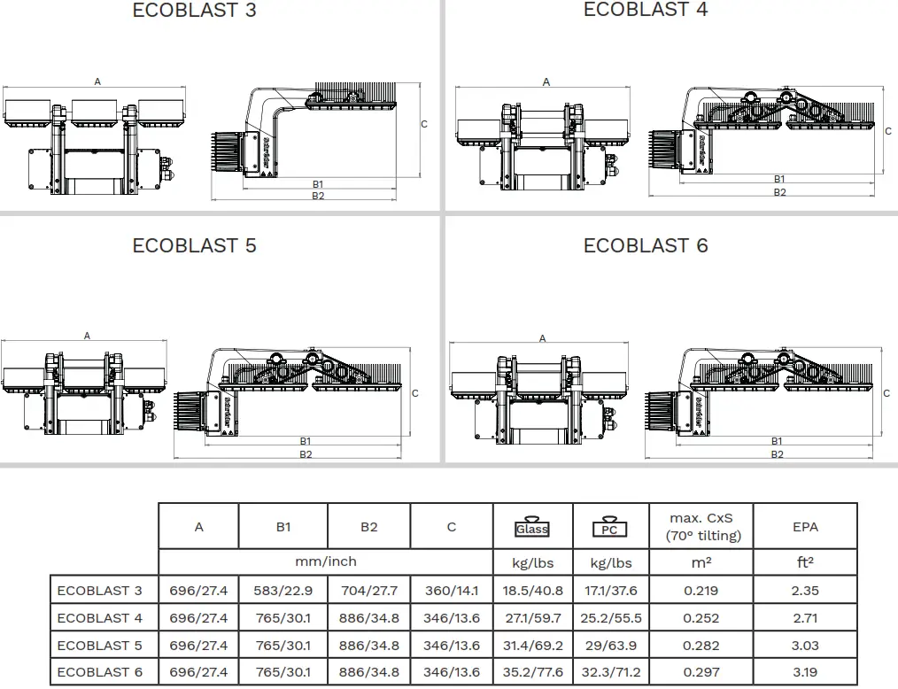
* Weights correspond to remote driver installation, with QPD connector for ECO BLAST 3-4, with Junction box for ECO BLAST 5-6. Attached driver means an additional 7.1kg (15.7 lbs) for ECO BLAST 3-4, an additional 7.5kg (16.5 lbs) for ECO BLAST 5-6 (including driver holder plates). Tolerance on weight values is +/-5%.
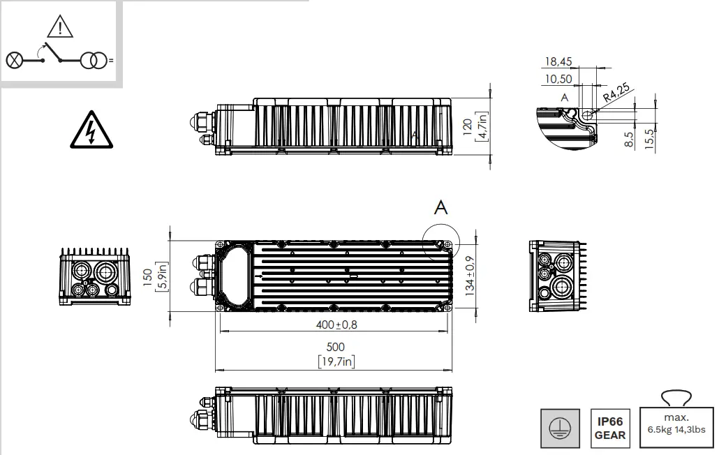
GEARBLAST – DRIVER OVERVIEW

LAYOUT AND MOUNTING
ECOBLAST 3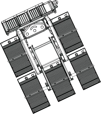
ECOBLAST 4-5-6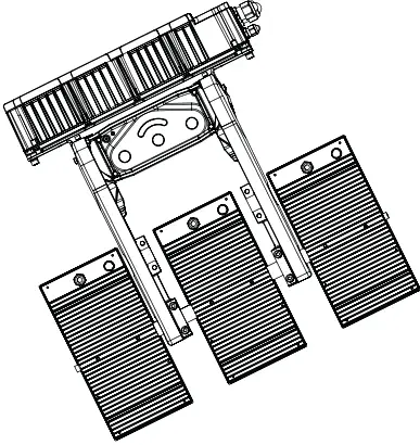 SAFETY CABLE
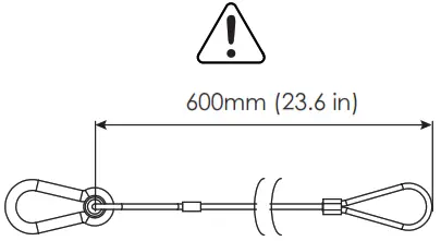
- For installations over 3 meters in height:
the secondary safety system application is mandatory, which is appropriated for the luminaire load (for example steel safety cable) - 600mm safety cable can be optionally ordered with the luminaire
Minimum screw requirement:
| Vibration standard | IEC 0.5g / ANSI 1.5g | ANSI 3g |
| Minimum fastener requirement | 1x M20 8.8 or A2-70 DIN9021 large plain washer | 1x M20 8.8 or A2-70 + 1x M10 8.8 or A2-70 DIN125 plain washers |
| Tightening torques | M20: 150-175 Nm | M20: 150-175 Nm M10: 35-40 Nm |
Recommended using an anti-seizing agent (Tikal Tef-Gel®)!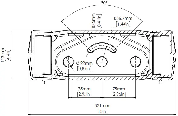 Fasteners not included in the package!
 ![]()
The relevant CSS and weight values can be found in this document.
DRIVER CONNECTION-DRIVER MOUNTED ON FORK

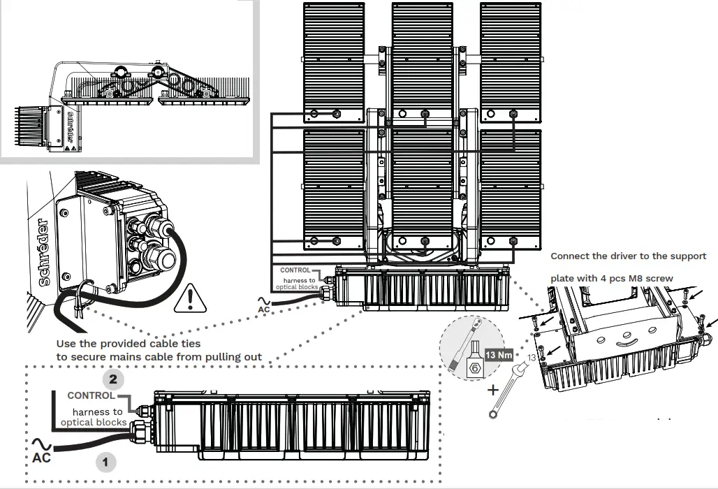
![]() AC and CONTROL cables must be connected by the installer
AC and CONTROL cables must be connected by the installer
 |  |
 REMOVE SCREWS REMOVE SCREWS | 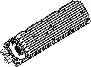 CONNECT THE AC, CONTROL, AND LED MODULE WIRES CONNECT THE AC, CONTROL, AND LED MODULE WIRES |
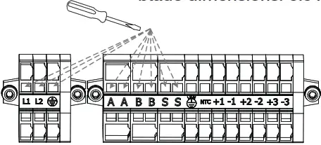 MAKE THE ELECTRICAL CONNECTION MAKE THE ELECTRICAL CONNECTIONblade dimensions: 3.5 x 0.5 mm | 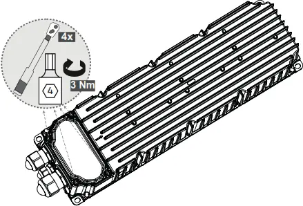 TIGHTEN THE DRIVER COVER TIGHTEN THE DRIVER COVER |
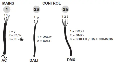
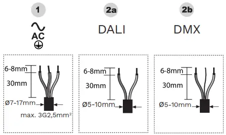
MAINS CONNECTION

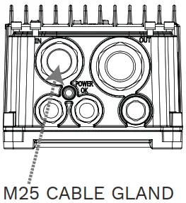
CLAMPING RANGE: 10-17MM![]()
In case of using a smaller outer diameter cable, please replace the cable gland’s internal gasket with the one attached in the packaging.
Modified clamping range: 7-13 mm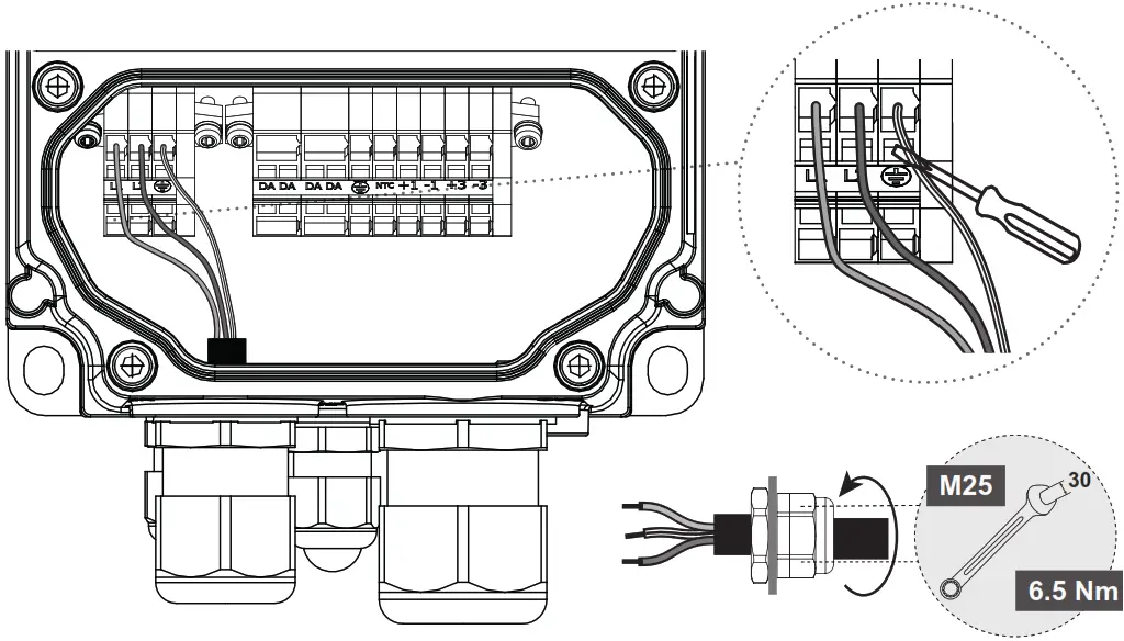
DALI

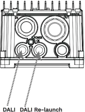
2X M16 CABLE GLAND
CLAMPING RANGE: 5-10MM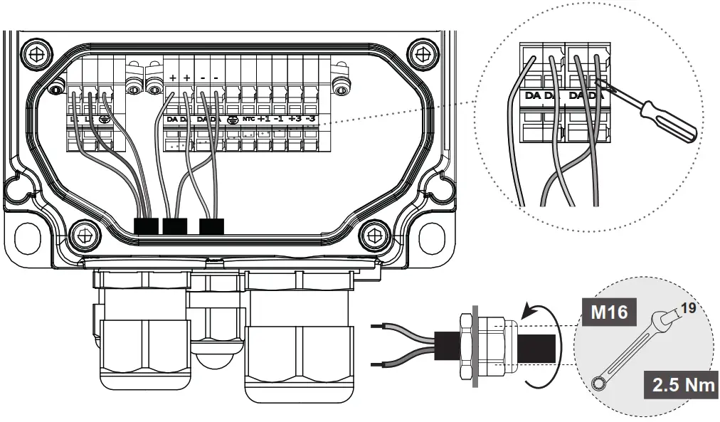
DMX

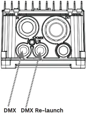
2X M16 CABLE GLAND
CLAMPING RANGE: 5-10MM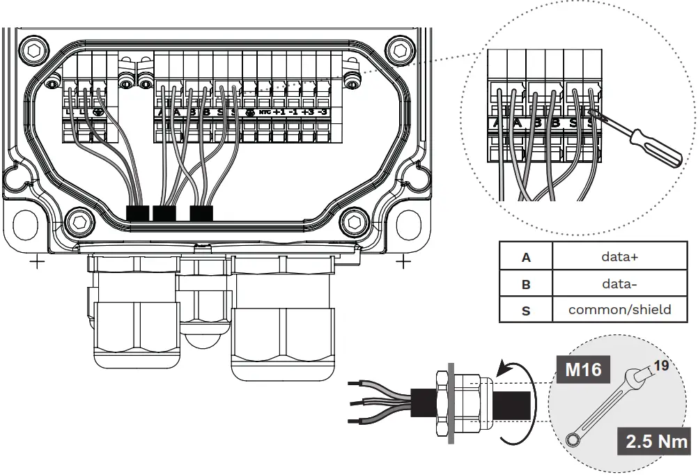
OPTICAL BLOCK

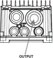
M32 CABLE GLAND
CLAMPING RANGE: 13-21MM![]() In case of using a smaller outer diameter cable, please replace the cable gland’s internal gasket with the one attached in the packaging.
In case of using a smaller outer diameter cable, please replace the cable gland’s internal gasket with the one attached in the packaging.
Modified clamping range: 8-14 mm
2 channels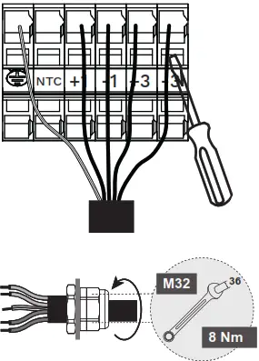
| CONNECTOR ID | CABLE ID EU | CABLE ID US |
| GND | Yellow/Green | Green |
| +1 | 1 / Brown | 1 / Pink |
| -1 | 2 / Blue | 2 / White |
| +3 | 3 / Black | 3 / Black |
| -3 | 4 / Grey | 4 /White-Black |
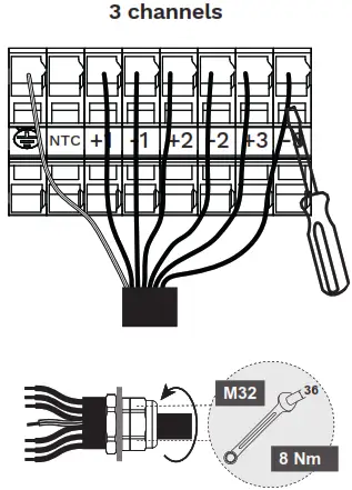
| CONNECTOR ID | CABLE ID EU | CABLE ID US |
| GND | Yellow/Green | Green |
| +1 | 1 | 1 / Pink |
| -1 | 2 | 2 / White |
| +2 | 3 | 3 / Black |
| -2 | 4 | 4 / White-Black |
| +3 | 5 | 5 / Blue |
| -3 | 6 | 6 / Orange |
DRIVER CONNECTION – REMOTE DRIVER INSTALLATION
 L<100m WIRE SIZE 1,5mm2 L<100m WIRE SIZE 1,5mm2100<L<200m WIRE SIZE 2,5mm2 MAX REMOTE DISTANCE 200M! | 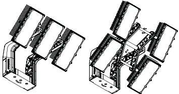 3 + 4 MODULE TYPES 3 + 4 MODULE TYPESAVAILABLE WITH QPD CONNECTOR | 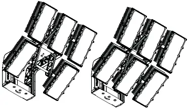 5 + 6 MODULE TYPES 5 + 6 MODULE TYPESAVAILABLE WITH JUNCTION BOX |
| QPD CONNECTOR TYPE (5-CORE WIRE) THE INTERCONNECTION CABLE IS NOT INCLUDED IN THE PACKAGE! 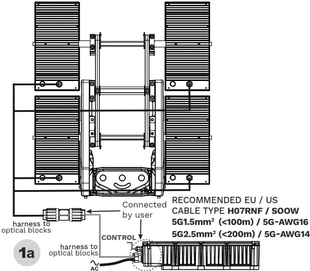 | JUNCTION BOX TYPE (7-CORE WIRE) THE INTERCONNECTION CABLE IS NOT INCLUDED IN THE PACKAGE! 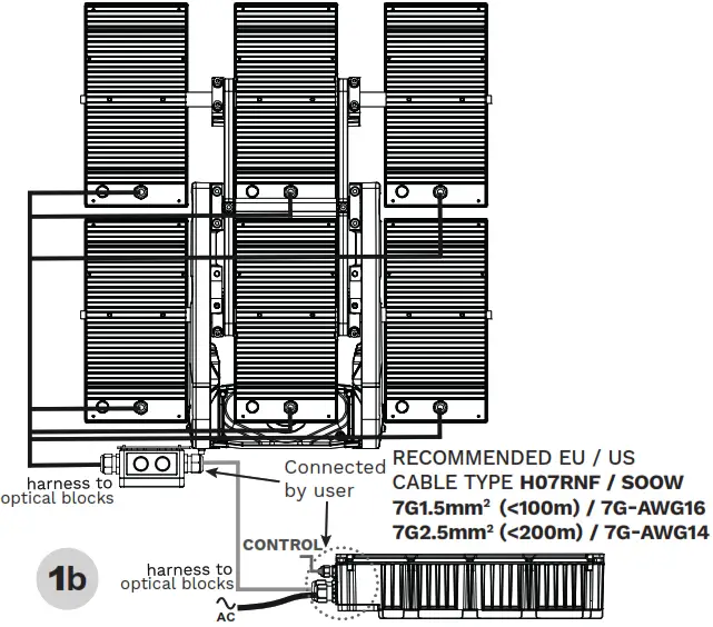 |
DRIVER CONNECTION ACCORDING TO PAGES 3-4-5
1a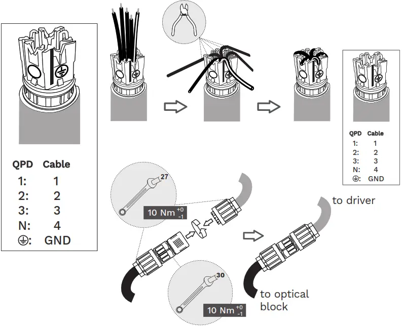
![]()
| DRIVER TERMINAL | QPD ID |
| GND | |
| 1 | 1 |
| -1 | 2 |
| 3 | 3 |
| -3 | 4 |
CLAMPING RANGE:
Ø9-16mm 5G1.5mm2 – 5G2.5mm2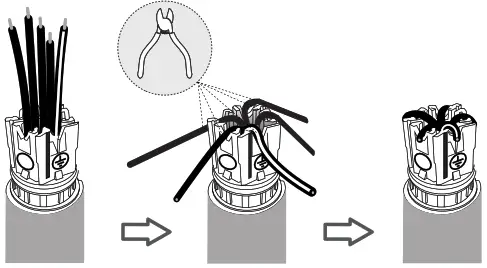
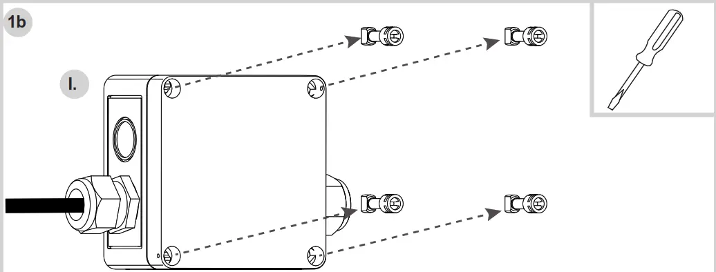
Remove screws from the junction box cover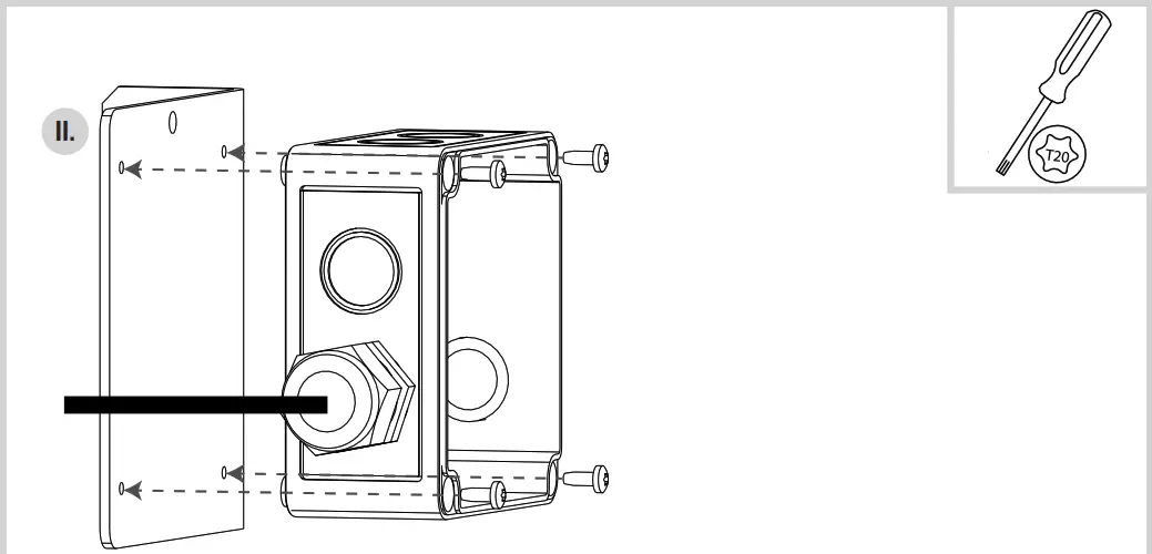
Connect the junction box to the junction box support plate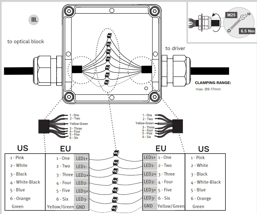
Make the electrical connection with WAGO terminal blocks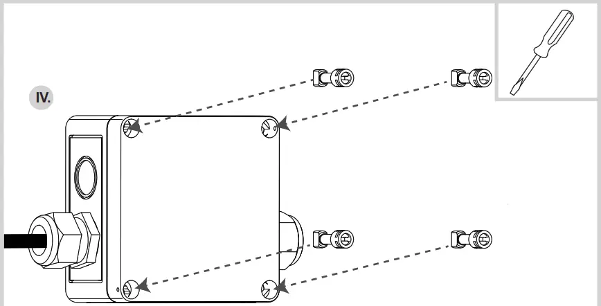
Tighten the junction box cover
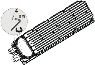
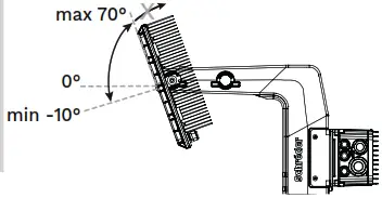
ANGLE ADJUSTMENT
ECOBLAST 3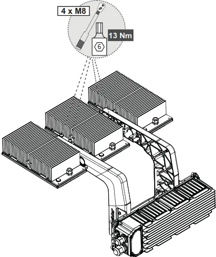
ALLOWED tilt angle is between -10° to 70° ![]()
STEPS
- Loosen the clamp screws (4xM8)
- Adjust the tilting angle
- Tighten the clamp screws with 13Nm
ANGLE LIMITATIONS
 |  |
| Direct installation | Suspended installation |
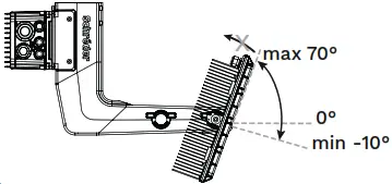
ECOBLAST 4-5-6
The swing arm inclination is adjustable in 5-degree increments relative to fork base
Separate scale sheet for adjusting optical block angles relative to the swing arm The inclination angle of the swing arm and the optical blocks can be adjusted separately![]() ALLOWED tilt angle is between -10° to 70°
ALLOWED tilt angle is between -10° to 70°
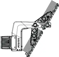
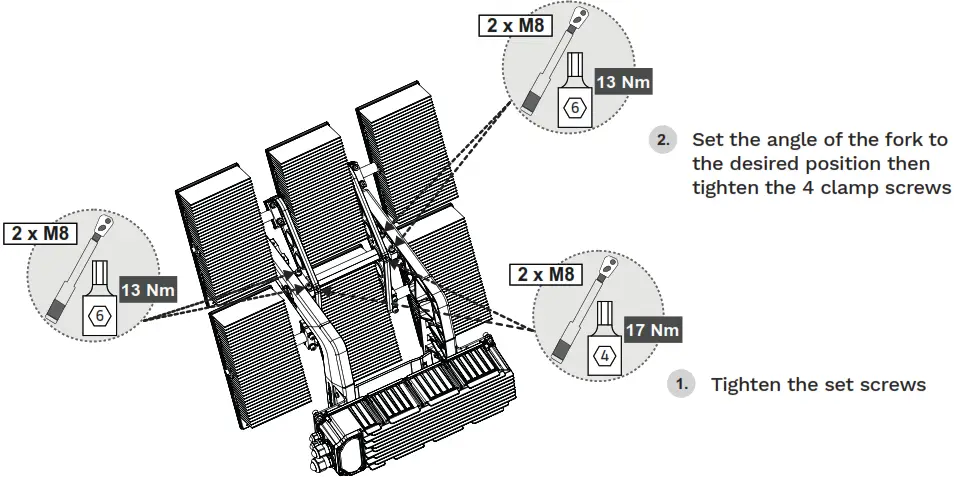
OFFSET LAYOUT INSTALLATION

REASSEMBLY STEPS
| Lay the complete luminaire with all optical block front faces touching the ground | 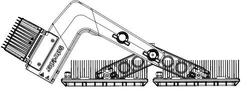 |
| Loosen the screws of the 2 main clamps and the 2 set screws of the brackets | 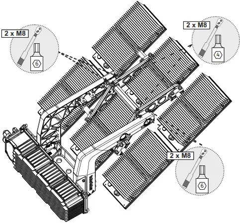 |
| Remove the shaft by rotating and pulling it in one direction | 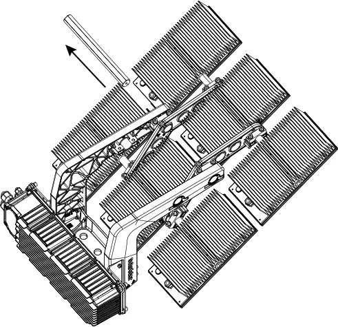 |
| Remove the 2 main clamps, 4 screws, nuts, washers, and anti-rotation clips from the initial position | 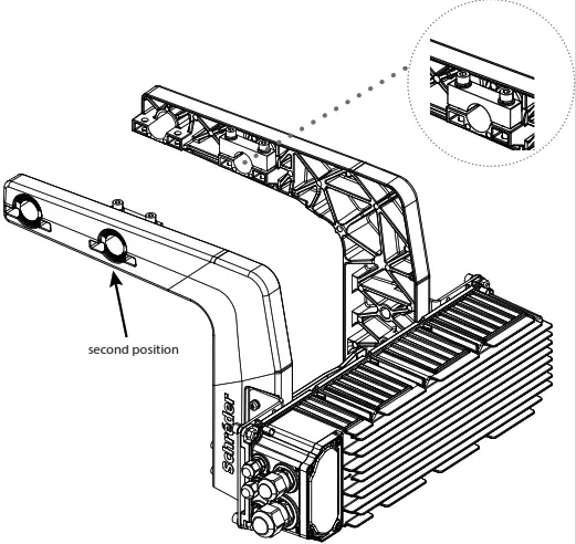 |
| Remove the 2 main clamps, 4 screws, nuts, washers, and anti-rotation clips from the initial position | 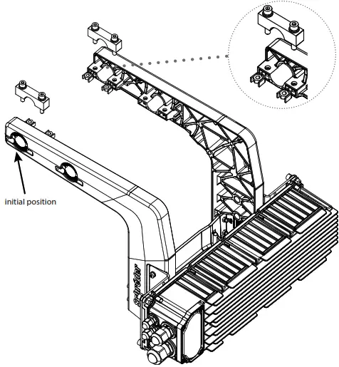 |
| Align the fork to the brackets with the 2nd position hole | 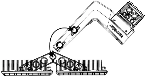 |
| Insert and rotate the shaft until the flat surface is toward the set screws in the brackets | 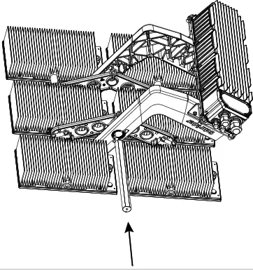 |
 |
OFFSET LAYOUT LIMITATIONS

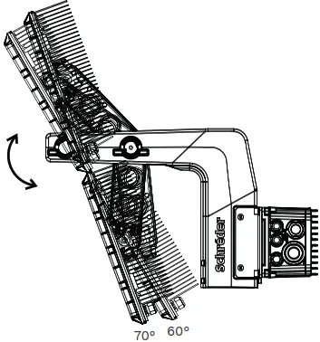
In the case of the standard mounting option, the angle of inclination can only be between 60° and 70° without any collision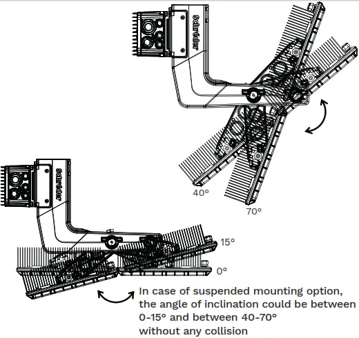
INRUSH DATA AND LUMINAIRES PER CIRCUIT BREAKER
The maximum number of LED drivers connectable to a single MCB is reported in the following table for each nominal input voltage. a maximum number of LED drivers connectable to a single MCB is reported in the following table for each nominal input voltage. Due to the different kinds of circuit breakers available on the market, this table just for reference. to the different kinds of circuit breakers available on the market, this table is just for reference.
1200 W
| VIN | Inrush Current Data | Drivers For Each Circuit Breaker | |||||||||||||||
| Nominal [VAC] | I peak [A] | Half Value Time [its] | Type B | Type C | Type D | ||||||||||||
| 10A | 16A | 20A | 25A | 32A | 10A | 16A | 20A | 25A | 32A | 10A | 16A | 20A | 25A | 32A | |||
| 220/240 | 26 | 6400 | 1 | 2 | 2 | 3 | 4 | 1 | 2 | 2 | 3 | 4 | 1 | 2 | 2 | 3 | 4 |
| 400 | 14 | 4700 | 2 | 3 | 4 | 5 | 6 | 2 | 3 | 4 | 5 | 6 | 2 | 3 | 4 | 5 | 6 |
1800 W
| VIN | Inrush Current Data | Drivers For Each Circuit Breaker | |||||||||||||||
| Nominal [VAC] | I peak [A] | Half Value Time [µs] | Type B | Type C | Type D | ||||||||||||
| 10A | 16A | 20A | 25A | 32A | 10A | 16A | 20A | 25A | 32A | 10A | 16A | 20A | 25A | 32A | |||
| 220/240 | 26 | 6400 | 1 | 1 | 2 | 2 | 3 | 1 | 1 | 2 | 2 | 3 | 1 | 1 | 2 | 2 | 3 |
| 400 | 20 | 1500 | 1 | 2 | 2 | 3 | 4 | 1 | 2 | 2 | 3 | 4 | 1 | 2 | 2 | 3 | 4 |
SAFETY INSTRUCTIONS
The light source contained in this luminaire shall only be replaced by the manufacturer or his service agent or a similarly qualified person. Always switch off the power prior to installation, maintenance, or repair activities.
RISK GROUP 2 – CAUTION! Hazardous optical radiation may be emitted from this product. Do not stare at the luminaire when operating as it may be harmful to the eyes. The luminaire should be positioned so that prolonged staring at the luminaire at a distance of fewer than 0.2m is not expected. This product contains a light source of an energy efficiency class G or higher. In the case of PVC insulated mains cable, the installer MUST ensure that the WHOLE cable is protected against climatic conditions, especially UV rays and rain, by making sure that the cable is contained inside the luminaire and pole
Y-connection: In case of damage to the wire, it has to be replaced only by the manufacturer, distributor, or an expert, to avoid risks.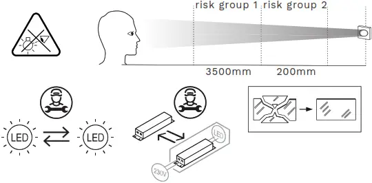
01-85-943 | DOC-0018707 rev J | 12-2021
www.schreder.com


