![]()
 Quick Start Guide
MMX2-4×1-H20
Important Safety Instructions
Please read the supplied safety instruction document before using the product and keep it available for future reference.
Introduction
Lightware’s MMX2 switcher series enhances and extends the possibilities of a meeting room and allows meeting participants to easily use their own devices such as laptops. MMX2-H20 series models offer 4K signal switching with numerous control interfaces (secure Ethernet, OCS sensor, GPIO, Audio, and RS-232 options). The device is the right choice for customers who need cost-effective 4×3 and 4×1 HDMI-only switchers with audio de-embedding, GPIO, Ethernet, and RS-232 but without USB transmission.MMX2-4×3-H20.
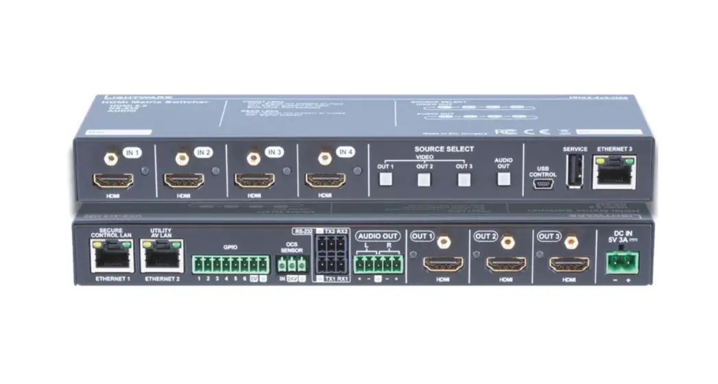
Front View (MMX2-4×3-H20)
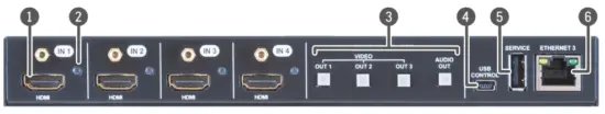
- HDMI input port for sources.
The applied cable shall not be longer than 5m (22AWG) when signal resolution is 4K.
Use cables certified for HDMI 2.0 (3x6Gbps) applications. - Input status
LED on: there is a valid signal on the port blink (once): the port is selected by a button press off: there is no valid signal on the port - Front panel buttons
For more details about the buttons see the Button Functionality section. When LEDs blink green three times after pressing the button, they show that the front panel lock is enabled. - USB mini-B port
Reserved for service functions. - USB-A port
Reserved for future developments. - Configurable
Ethernet port RJ45 connector for configurable 100 Base-T Ethernet communication.
Front View (MMX2-4×3-H20)
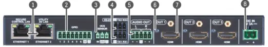
| 1. Ethernet ports | RJ45 connectors for 100Base-T Ethernet ommunication. | 5 Analog audio port | Audio output port (5-pole Phoenix) for the balanced analog audio output signal. The signal is de-embedded from the selected video signal. |
| 2 GPIO port | 8-pole Phoenix ® connector for configurable general purpose. Max. input/output voltage is 5V, see the details on the next page | 6 Output status LED | on: video signal is present off: video signal is not present or muted |
| 3 OCS sensor | 3-pole Phoenix ® connector (male) for connecting an occupancy sensor. The port provides 24V output voltage (50mA). | 7 HDMI output port | HDMI output ports for connecting to the sink devices. |
| 4 RS-232 port | 3-pole Phoenix ® connector for bi-directional RS-232 communication. | 8 DC input | The device can be powered by an external 5V power supply. Connect the output to the 2-pole hoenix® connector. |
MMX2-4×1-H20
Use IN1, IN2, IN3, or IN4 button for selecting the video source to the HDMI output.
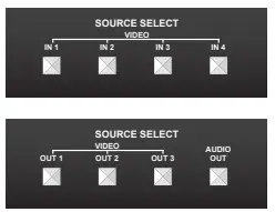
MMX2-4×3-H20
Use the OUT1, OUT2, or OUT3 button for selecting the video source for the specific output. Push OUT1 to select the video input for the HDMI OUT1 port (OUT2 for HDMI OUT2 and OUT3 for HDMI OUT3). The sequence of each output button is the following: OUT 1
Use the AUDIO OUT button for switching the audio source to the analog audio output. The sequence is the same as above. Setting a Dynamic IP Address (DHCP)

- Keep the button on the right (AUDIO OUT on MMX2-4×3-H20; IN4 on MMX2-4×1-H20 model) button pressed for 5 seconds; all front panel LEDs start to blink.
- Release the button, then press it 3 times quickly. DHCP is now enabled.
Restore the Factory Default Settings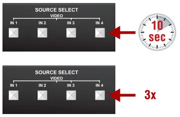
- Keep the button on the right (AUDIO OUT on MMX2-4×3-H20; IN4 on MMX2-4×1-H20 model) pressed for 10 seconds.
- If the LEDs blink fast, release the button, press it again 3 times quickly, then the device restores the factory default settings and reboots.
Lock/Unlock Buttons
Press the left and right buttons together (within 100 ms) (IN1 and IN4 buttons in MMX2-4×1-H20 model, OUT1 and AUDIO OUT on MMX2-4×3-H20 model) to disable/ enable front panel buttons; front panel LEDs blink 4 times when locking/ unlocking.
Software Control – Using Lightware Device Controller (LDC)
The device can be controlled from a computer using the Lightware Device Controller software. The application is available at www.lightware.com, install it on a Windows PC or a macOS and connect to the device via LAN. 
Firmware Update
Lightware Device Updater v2 (LDU2) is an easy and comfortable way to keep your device up-to-date. Establish the connection via Ethernet. Download and install LDU2 software from www.lightware.com where you can find the latest firmware package as well.
Box Contents
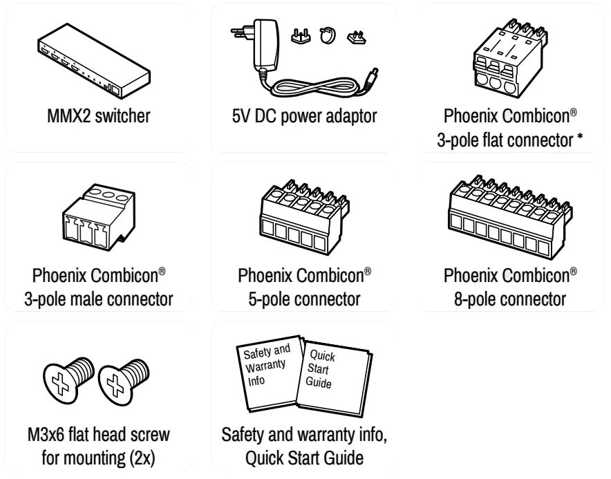
* 2 pcs. for MMX2-4×3-H20 and 1 pc. for MMX2-4×1-H20 model (for RS-232 port)
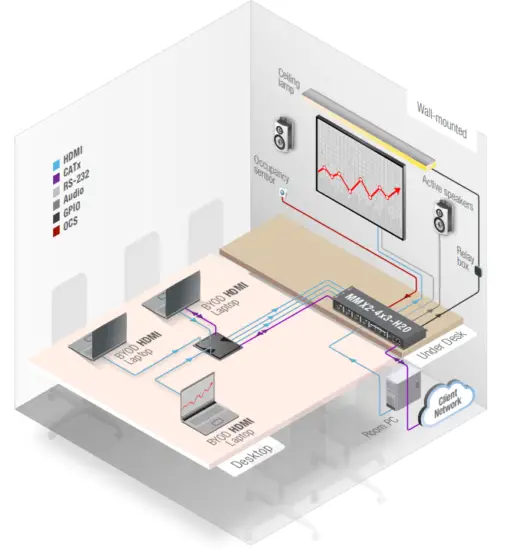
Connecting Steps (example for MMX2-4×3-H20)
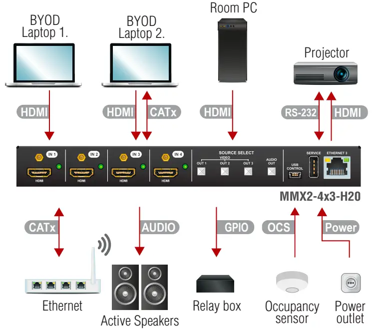
| HDMI | Connect an HDMI source (e.g. BYOD laptop or room PC) to the HDMI input port. |
| CATx | Connect the Ethernet port to a Local Network Switch to provide an Ethernet connection for device configuration and/or for a source device (only on MMX2-4×3-H20). |
| CATx | Connect the switcher to an Ethernet Ethernet port to access the local network. |
| HDMI | Connect an HDMI sink (e.g projector) to the HDMI output port. |
| RS-232 | Optionally connect a controller/controlled device (e.g. projector) to the RS-232 port. |
| Audio | Optionally connect an audio device (e.g. active speakers) to the analog audio output port by an audio cable. |
| GPIO | Optionally connect a device (e.g. Relay box ) to the GPIO port. |
| OCS | Optionally connect an occupancy sensor to the OCS port. |
| Power | Connect the external power supply to the AC power socket and then to the switcher unit. |
![]() Powering the device is recommended as the final step.
Powering the device is recommended as the final step.
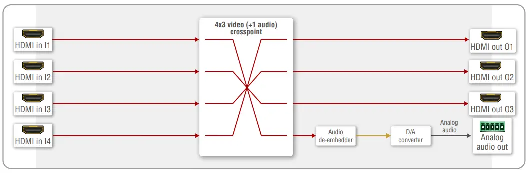
Port Diagram (MMX2-4×3-H20)
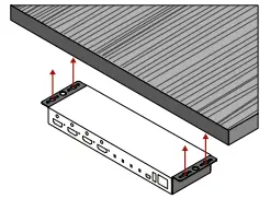
Mounting the Device (with optionally available accessory)
The below example demonstrates the application of the UD Kit double accessory (to order mounting accessories please contact [email protected]):
![]() Using different (e.g. longer) screws may cause damage to the device.
Using different (e.g. longer) screws may cause damage to the device.![]() The transmitter is half-rack-sized.
The transmitter is half-rack-sized.
Factory Default Settings
The settings can be restored by front panel buttons as written on the previous page or by software tools. The factory default values are the following:
| IP address | Dynamic (DHCP is enabled) |
| Hostname | FlightAware-<serialno> |
| Video Crosspoint (MMX2-4×3-H20) | I1@O1, I2@O2, I3@O3 |
| Video Crosspoint (MMX2-4×1-H20) | I1@O1 |
| HDCP mode (output) | Auto |
| Signal type | Auto |
| Emulated EDID | F47 – (Universal HDMI with PCM audio) |
| Analog audio output | I1 is selected |
| Analog audio output levels | Volume (dB): 0.00; Balance: 0 (center) |
| Audio Autoselect | Follow video O1 |
| RS-232 port setting | 9600 BAUD, 8, N, 1 |
| RS-232 serial over IP | Enabled |
| HTTP, HTTPS | Enabled |
| HTTP, HTTPS authentication | Disabled |
OCS (Occupancy) Sensor
The switcher is supplied with a 3-pole Phoenix® connector (male) for connecting an OCS sensor.
Connector Pin Assignment
| Pin nr | Function |
| 1 | input with logic low/high level |
| 2 | 24V (max 50mA) |
| 3 | ground |
Signal Levels
| The signal levels for the Pin 1 | Input voltage (V) | Max. current (mA) |
| Logic low level | 0 – 0.8 | 30 |
| Logic high level | 5-Feb | 18 |
 The occupancy sensor connector and GPIO port are not compatible with each other because of the voltage level difference, please do not connect them directly.
GPIO (General Purpose Input/Output Ports)
The device has seven GPIO pins which operate at TTL digital signal levels and can be set to high or low levels (Push-Pull). The direction of the pins can be input or output (adjustable).
Connector Pin Assignment
| Pin nr | Function |
| 6-Jan | configurable |
| 7 | 5V (max. 500mA) |
| 8 | ground |
Signal Levels
| Input voltage (V) | Output voltage (V) | Max. current (mA) | |
| Logic low level | 0 – 0.8 | 0 – 0.5 | 30 |
| Logic high level | 5-Feb | 4.5 – 5 | 18 |
Plug pin assignment 1-6: Configurable, 7: 5V (max. 500 mA); 8: Ground
The recommended cable for the connectors is the AWG24 (0.2 mm2 diameters) or the generally used ‘alarm cable’ with 4×0.22 mm2 wires.
![]() The maximum total current for the six GPIO pins is 180 mA, the max. supported input/output voltage is 5V.
The maximum total current for the six GPIO pins is 180 mA, the max. supported input/output voltage is 5V.
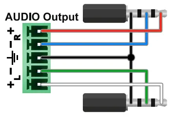
Audio Cable Wiring Guide
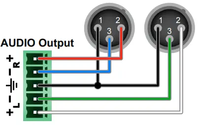
The device is built with 5-pole Phoenix output connectors. See below a few examples of the most common assembling cases.
| Balanced output to balanced input Phoenix – 2×6.3 (1/4”) TRS | Balanced output to balanced input Phoenix cable – 2x XLR plugs |
 |  |
| Balanced output to an unbalanced input Phoenix – 2x RCA | Balanced output to an unbalanced input Phoenix – 2x 6.3 (1/4”) TS |
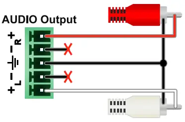 | 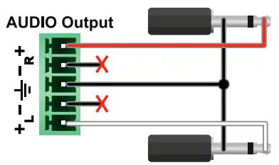 |
RS-232 Port
The switcher provides a 3-pole Phoenix connector for bi-directional serial communication.
Connector Pin Assignment The switcher provides a 3-pole Phoenix connector for bi-directional serial communication.
Connector Pin Assignment
| Pin nr. | Function |
| 1 | ground |
| 2 | TX data |
| 3 | RX data |
Signal Levels
| Output voltage (V) | |
| Logic low level | 15-Mar |
| Logic high level | -18 |
Typical Application Diagram
Further Information
The document is valid with the following firmware version: 1.3.0 The User’s manual for this appliance is available on www.lightware.com. See the Downloads section on the dedicated product page.
Contact Us
[email protected]
+36 1 255 3800
[email protected]
+36 1 255 3810
![]() Lightware Visual Engineering LLC.
Lightware Visual Engineering LLC.
Peterdy 15, Budapest H-1071, Hungary
Doc. ver.: 1.2
19200188


