
HALL RESEARCH SW-HD-4A 4×1 HDMI Switch
Introduction
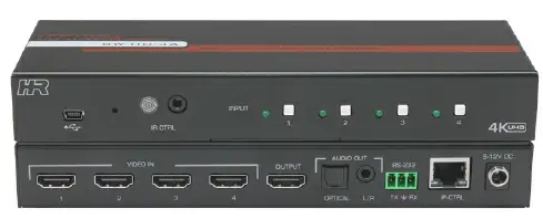
The SW-HD-4A is a 4 input HDMI Switch with advanced switching technology enabling fast switching of four HDMI sources to a single HDMI output.
The switcher supports resolutions up to 4K60 4:4:4 (UHD), 3D, and 36-bit deep color video. Switching can be controlled via front panel buttons, IR remote control, RS-232, Telnet, or a built-in Web GUI. EDID management is provided, whereby you can select the EDID table for all the inputs from a list of standard EDID’s or copy the EDID from the connected display to all inputs. This can be done using the Web GUI or by sending RS-232 commands. The SW-HD-4A provides a mini-USB port on the front for firmware upgrades. This USB connector also provides 500 mA of power and can be used to power external devices such as Google™ Chromecast or Amazon™ Fire TV.
Features
- Fast switching technology reduces switching time.
- Front panel LED indicators for status monitoring
- Supports resolutions up to 4K60 4:4:4
- Supports 3D, HDR and deep color
- Control via front panel, IR, RS-232, Telnet and Web GUI
- Includes IR remote control
- Plug and play installation
- HDMI 2.0, HDCP 2.2 and below, and DVI 1.0 compliant
- High-definition audio pass-through
- Analog Stereo and Digital multi-channel audio extraction
- EDID emulation or pass-through
- USB port can power external devices such as video players

Package Contents
- Qty (1) Model SW-HD-4A
- Qty (1) Locking 12V DC Universal Power Supply
- Qty (2) Mounting brackets
- Qty (4) Rubber Feet with adhesive
- Qty (1) IR Remote Control
- Qty (1) IR Remote Detector cable
- Qty (1) User’s Manual Card
*All packages are carefully inspected prior to shipment. However, if you think that you are missing an accessory, please contact Hall Research Support for further assistance.
Installation
The following diagram illustrates a typical system setup.

4×1 4K60 HDMI Switch with Control and Audio Extraction
Configuration
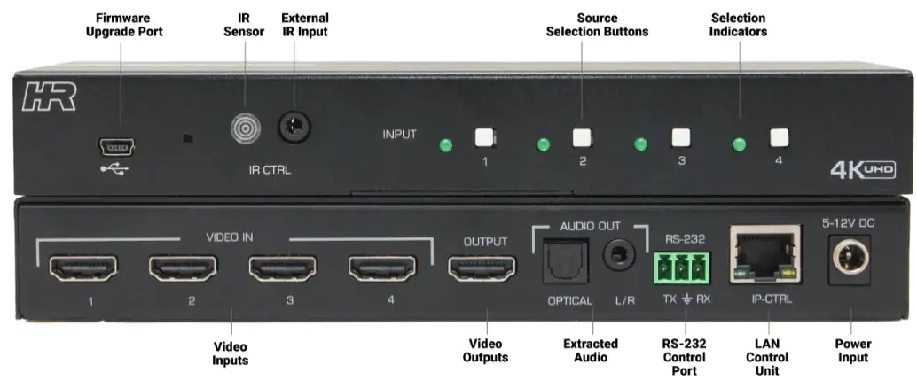
- Connect all video sources to the VIDEO IN connectors
- Connect the display device to the OUTPUT connector
- Connect the Power Supply to the power input
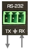
- Connect any external controller or PC to the RS-232 terminal block, if required.
- Connect IP-CTRL port to compatible LAN network, if required.
- Connect IR detector to external IR CTRL port, if required.
Operation
The unit can be controlled via front panel and via external control options like IR remote control, RS-232, Telnet and/or the Web GUI.
- Press the desired INPUT button switch to display the available video on the HDMI output.
- The illuminated LED shows which input is directed to the OUTPUT connector.
- Press and hold INPUT button #1 for 7 seconds, then release to factory reset the unit to default settings.
- Press and hold INPUT button #4 for 7 seconds to start cycling through each input at a 1-minute rate
- Press and hold INPUT button #4 for 11 seconds to stop cycling through each input.
- The USB port can be used for firmware upgrades or powering external devices.
- The IR remote control supplied with the unit can be used to select the desired HDMI INPUT, MUTE the HDMI OUTPUT audio or turn the system on or off (Unit will always be ON after a power cycle).

RS-232 and Telnet Commands
- 115200 baud, No Parity, 1 Stop Bit
- Telnet operation is via port # 6324 of the IP address setting
- All commands are in ASCII format
- Commands are NOT case sensitive.
- Each command must be terminated by a single character <CR> (0x0D)
- Unknown commands respond with “INVALID COMMAND”
- All responses are terminated with <CR><LF> (0x0D, 0x0A)
| Command | Response | Function | ||||
| DN | Query Device Name | SW-HD-4A | ||||
| SWn
Where: n = HDMI Input[1 to 4] | Switch to HDMI source | SWn
Where: N = HDMI Input[1 to 4] | ||||
| SW? | Query switch state | SWn
Where: N = HDMI Input[1 to 4] | ||||
| EMn
Where: |
Set EDID Mode | EMn
Where: | ||||
| n | Mode | n | Mode | |||
| 0 | Pass-through | 0 | Pass-through | |||
| 1 | Static | 1 | Static | |||
|
EM? |
Query EDID Mode | EMn
Where: | ||||
| n | Mode | |||||
| 0 | Pass-through | |||||
| 1 | Static | |||||
| EDn
Where: |
Select Static EDID.
NOTE: Static EDID is served to all the inputs when EDID Mode is EM1. | EDn
Where: | ||||
| n | EDID | n | EDID | |||
| 0 | 4K2K@60 2 CH | 0 | 4K2K@60 2 CH | |||
| 1 | 4K2K@60 AC3 | 1 | 4K2K@60 AC3 | |||
| 2 | 4K2K@60 4:2:0 2 CH | 2 | 4K2K@60 4:2:0 2 CH | |||
| 3 | 4K2K@60 4:2:0 AC3 | 3 | 4K2K@60 4:2:0 AC3 | |||
| 4 | 1080P@60 2 CH | 4 | 1080P@60 2 CH | |||
| 5 | 1080P@60 AC3 | 5 | 1080P@60 AC3 | |||
| 6 | 720P@60 2 CH | 6 | 720P@60 2 CH | |||
| 7 | 720P@60 AC3 | 7 | 720P@60 AC3 | |||
|
ED? |
Query Static EDID Index. | EDn
Where: | ||||
| n | EDID | |||||
| 0 | 4K2K@60 2 CH | |||||
| 1 | 4K2K@60 AC3 | |||||
| 2 | 4K2K@60 4:2:0 2 CH | |||||
| 3 | 4K2K@60 4:2:0 AC3 | |||||
| 4 | 1080P@60 2 CH | |||||
| 5 | 1080P@60 AC3 | |||||
| 6 | 720P@60 2 CH | |||||
| 7 | 720P@60 AC3 | |||||
4×1 4K60 HDMI Switch with Control and Audio Extraction
| Command | Response | Function | ||||||
|
HDI? |
Query HDMI Input Status
THIS COMMAND NOT AVAILABLE IN TELNET SESSION | HDIn,m
Where: n = HDMI Input [1 to 4]
m = HDMI State | ||||||
| m | State | |||||||
| 0 | Source not Connected | |||||||
| ? | State Unknown | |||||||
| 1 | Source Connected | |||||||
| 2 | HDCP1.4 Encrypted | |||||||
| 3 | HDCP2.2 Encrypted | |||||||
|
HDO? |
Query HDMI Output Status | HDOm
Where: | ||||||
| m | State | |||||||
| 0 | Sink not Connected | |||||||
| ? | State Unknown | |||||||
| 1 | Sink Connected | |||||||
| 2 | HDCP1.4 Encrypted | |||||||
| 3 | HDCP2.2 Encrypted | |||||||
| AUn Where: | Set HDMI Output Audio state
NOTE THIS IS ONLY THE HDMI OUTPUT AUDIO.
THE 3.5 mm Extracted Audio is ALWAYS ON from the currently selected Input | AUn Where: | ||||||
| n | Mode | n | Mode | |||||
| 0 | Mute OFF | 0 | Mute OFF | |||||
| 1 | Mute ON | 1 | Mute ON | |||||
|
AU? |
Query HDMI Output audio state | AUn
Where: | ||||||
| n | Mode | |||||||
| 0 | Mute OFF | |||||||
| 1 | Mute ON | |||||||
| LKn
Where: |
Lock Front Panel | LKn
Where: | ||||||
| n | Mode | n | Mode | |||||
| 0 | Lock OFF | 0 | Lock OFF | |||||
| 1 | Lock ON | 1 | Lock ON | |||||
|
LK? |
Lock Status Query | LKn
Where: | ||||||
| n | Mode | |||||||
| 0 | Lock OFF | |||||||
| 1 | Lock ON | |||||||
|
IPCONFIG | Show current IP, Subnet Mask and Gateway addresses
THIS COMMAND NOT AVAILABLE IN TELNET SESSION | IP : xxx.xxx.xxx.xxx MASK : xxx.xxx.xxx.xxx GATEWAY: xxx.xxx.xxx.xxx | ||||||
SW-HD-4A
| Command | Response | Function |
| IP [IPv4 Address] | Set IP Address | xxx.xxx.xxx.xxx [IPv4 Address] |
| IP? | Query IP Address | xxx.xxx.xxx.xxx [IPv4 Address] |
| SN [IPv4 Address] | Set Subnet | xxx.xxx.xxx.xxx [IPv4 Address] |
| SN? | Query subnet | xxx.xxx.xxx.xxx [IPv4 Address] |
| GW [IPv4 Address] | Set Gateway | xxx.xxx.xxx.xxx [IPv4 Address] |
| GW? | Query Gateway | xxx.xxx.xxx.xxx [IPv4 Address] |
| FW | Query Firmware Version | V1.0 |
| FD | Factory Default | Factory Default SW-HD-4A V1.0 |
| REBOOT | Reboots the unit | REBOOT SW-HD-4A V1.0 |
| PWn
Where: n = 0 = Output Blanked, all LEDs off n = 1 = Output On, Selected input active | Simulates a power condition | PWn
Where: n = 0 = Output Blanked, all LEDs off n = 1 = Output On, Selected input active |
4×1 4K60 HDMI Switch with Control and Audio Extraction
Web GUI Operation
As shipped from the factory (or after factory default reset), the SW-HD-4A IP address is set for a static IP address of 192.168.0.88 and a static GW (Gateway) address of 192.168.0.1. Use RS-232 terminal software to find the currently assigned IP and GW addresses (and to also set them as desired).
SW-HD-4A internal Web pages (Web GUI)
- Access the SW-HD-4A Webpage with any compatible browser at the IP address found above. The browser will open with the devices Switch Info tab displayed. Click the tabs at the top of the screen to access the other tabs.
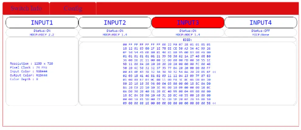
- Switch Info Tab

- INPUT 1 thru INPUT 4
- Shows the currently selected HDMI input.
- Click the desired INPUT button to select that HDMI input.
- The following information is also shown
- HDMI Input Status (ON or OFF)
- HDMI HDCP Input State (None, HDCP 1.4 or HDCP 2.2)
- Resolution
- Pixel Clock
- Output Color Space
- Color Bit Depth
- EDID presented to the HDMI Input based on the configuration setting.
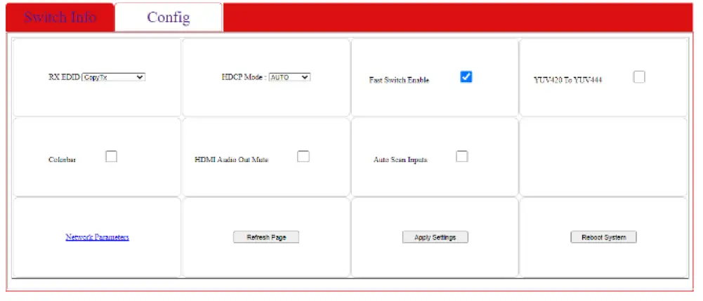
- CONFIG Tab

- RX EDID
- Controls the EDID selection presented to each of the HDMI inputs
- HDCP Mode
- Controls the HDMI Output HDCP setting
- Fast Switch Enable
- Controls the Fast Switch configuration. This defaults to ON
- YUV/420 to YUV/444
- Controls whether the HDMI Input color space is converted to YUV/444 on the HDMI Output
- Color bar
- Controls whether a Color Bar pattern is sent to the HDMI OUTPUT
- HDMI Audio Out Mute
- Controls whether the HDMI OUTPUT Audio is muted or not
- Auto Scan Inputs
- Controls whether the HDMI Inputs are automatically switched at a 1-minute cycle rate
- Network Parameters
- Used to set the network IP, Subnet, and Gateway
- Refresh Page
- Click this button to update the webpage settings.
- Apply Settings
- Click this button to apply any changes to the webpage settings.
- Reboot System
- Reboots the system
Input Channel Scanning
The SW-HD-4A can automatically cycle through each of the connected HDMI Inputs. In this mode, each HDMI Input is displayed for 1 minute before changing to the next HDMI input. Auto-scan Mode can be enabled and disabled by external command (Web GUI), or via the front panel pushbuttons.
- To enable from front panel, press and hold INPUT#1 button for 7 seconds. After releasing the INPUT button the scanning will start automatically.
- To disable from front panel, press and hold INPUT#1 button for 11 seconds. After releasing the INPUT button the scanning will be stopped.
- To enable or disable from WebGUI, select, or deselect the “Auto Scan Inputs” option. Then select “Apply Settings” in Config tab.
4×1 4K60 HDMI Switch with Control and Audio Extraction
Front Panel Lock
Front panel buttons of SW-HD-4A can be locked via the Web GUI, RS-232, or Telnet to prevent users from switching or changing modes. When the front panel lock is enabled, attempts to change the input selection from the front panel will be ignored. Note that changes via RS-232, Web GUI and IR Remote control still change the settings.
To re-enable the front panel buttons, send the un-lock or factory default command to the unit from the Web GUI, RS-232, or via Telnet.
Factory Default
If the INPUT #4 button is pressed and held for 7 seconds when the unit is operational with the power already applied, the system parameters are reset to the FACTORY DEFAULT values.
EDID Settings
The EDID settings can only be changed using RS-232, Telnet, or the Web GUI. Two settings affect how the EDID is presented to the HDMI source devices. EMx and EDx.
- The default EDID mode (EM0) is to pass the EDID of the SINK connected to the HDMI OUTPUT to the HDMI INPUT connectors.
- If the EDID mode is set to EM1, the static emulated EDID selected below is used.
- If there is no SINK device connected to the HDMI OUTPUT connector, an emulated EDID (EDx) is presented to the SOURCE device connected to the HDMI INPUT connectors.
The table below lists each of the emulated EDID tables available.
| EDID Setting (EDx) | EDID | Description |
| 0 | 4K2K@60 2 CH | Built-In EDID with Deep color, 2D3D/ PCM audio format / 4K2K native resolution |
| 1 | 4K2K@60 AC3 | Built-In EDID with Deep color, 2D3D/ AC3 Digital audio format / 4K2K native resolution |
| 2 | 4K2K@60 4:2:0 2 CH | Built-In EDID with Deep color, 2D3D/ PCM audio format / 4K2K 4:2:0 native resolution |
| 3 | 4K2K@60 4:2:0 AC3 | Built-In EDID with Deep color, 2D3D/ AC3 Digital audio format / 4K2K 4:2:0 native resolution |
| 4 | 1080P@60 2 CH | Built-In EDID with 8-bit color depth, 2D3D/ PCM audio format /1080p native resolution |
| 5 | 1080P@60 AC3 | Built-In EDID with 8-bit color depth, 2D3D/ AC3 Digital audio format / 1080p native resolution |
| 6 | 720P@60 2 CH | Built-In EDID with 8-bit color depth/ 2D3D/ PCM audio format/ 720p native resolution |
| 7 | 720P@60 AC3 | Built-In EDID with 8-bit color depth, 2D3D/ AC3 Digital audio format/ 720p native resolution |
Troubleshooting
There are no field serviceable parts or circuits in the device. Opening the unit will void the warranty
Contacting Hall Research
If you determine that the SW-HD-4A is malfunctioning, do not attempt to repair the unit instead, contact Hall Research Technical Support at 800-959-6439 or
[email protected]. Before you do, make a record of the history of the problem. We will be able to provide more efficient and accurate assistance if you have a complete description.
Shipping and Packaging
If you need to transport or ship your unit:
- Package it carefully. We recommend that you use the original container.
- Before you ship the units back to Hall Research for repair or return, contact us to get a Return Authorization (RMA) number.
Specifications
| Video Resolution | HDTV signal 480i through 4K/60 4:4:4 DVI//PC signal VGA (640×480) thru WQXGA@30 |
| Video Bandwidth | Up to 18 Gbps total |
| Audio Standards | LPCM 2/5.1/7.1 CH, Dolby Digital 2-5.1 CH, DTS 2-5.1 CH, Dolby TrueHD and DTS-HD Master Audio |
| Video Connectors | HDMI (4x INPUT, 1x OUTPUT) |
| Audio Connectors | 3.5 mm Stereo Analog Optical SPDIF Digital (TOSLINK) |
| Other Signals | (1) RX, TX and GND on Terminal Strip RS-232 Baud Rate: 115200, N, 8, 1 |
| USB-Mini for firmware update (1) RJ45 LAN | |
| ESD Protection | Human Body model: 8 kV (air-gap discharge) 4 kV (contact discharge) |
| Dimensions | Product: 7.96” (202 mm) W x 2.96” (75 mm) D x 1.15” (29 mm) H Shipping: 12” W x 10” D x 4” H |
| Weight | Product: 0.95 lbs (0.43 kg) Shipping: 2.4 lbs (1.09 kg) |
| Enclosure | Metal |
| Operating Temperature | Storage: -40 to +158 °F (-40 to +70 °C) / 10% to 90%, non-condensing Operating: +32 to +122 °F (0 to +50 °C) / 10% to 90%, non-condensing |
| MTBF | 90,000 hours calculated estimate |
| Warranty | 3 years parts and labor |
| IR Remote Protocol | NEC or NEC Extended |
| IR MUTE ON/OFF IR POWER ON/OFF | 0x00, 0xBF, 0x00, 0xFF 0x00, 0xBF, 0x02, 0xFD |
| IR INPUT #1 | 0x00, 0xBF, 0x09, 0xF6 |
| IR INPUT #2 | 0x00, 0xBF, 0x0D, 0xF2 |
| IR INPUT #3 | 0x00, 0xBF, 0x11, 0xEE |
| IR INPUT #4 | 0x00, 0xBF, 0x15, 0xEA |


