
sengled BT001 Mesh BLE 5.0 Module

Introduction
BT001 intelligent lighting module is a Bluetooth 5.0 low power module based on TLSR825Xchip. The BluetoothmodulewithBLEandBluetoothmesh networking function, Peer to peer satellite network communication, using Bluetoothbroadcastforcommunication,canensuretimelyresponseincaseofmultiple devices.Itismainlyusedinintelligentlightcontrol.Itcanmeettherequirementsof low power consumption, low delay and short distance wireless datacommunication.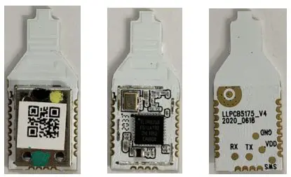
Features
- TLSR825xF512ETsystemonchip
- Built-inFlash512KBytes
- Compactsize28x12
- Upto6channelsPWM
- HostControllerInterface(HCI)overUART
- Class1supportedwith10.0dBmmaximumTXpower
- BLE5.01Mbps
- Stampholepatchpackage,easytomachinepaste
- PCBantenna
Applications
- LEDLightingcontrol
- SmartDevicesSwitch,RemoteControl
- SmartHome
Module Diagram
TLS825xSoCdiagram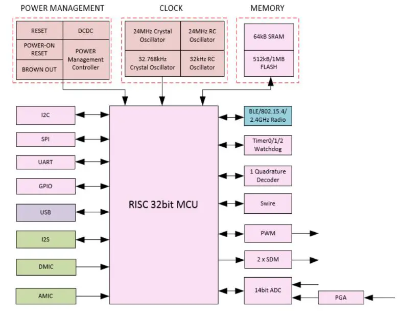
ModulePinsAssignments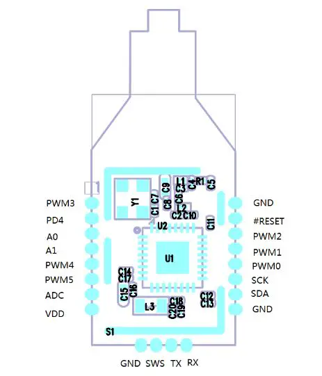
Pins Description
| Pin | NAME | I/O | Description | TLSR |
| 1 | PWM3 | I/O | PWMoutput | TLSR825xPIN31 |
| 2 | PD4 | I/O | GPIO | TLSR825xPIN1 |
| 3 | A0 | I/O | GPIO | TLSR825xPIN3 |
| 4 | A1 | I/O | GPIO | TLSR825xPIN4 |
| 5 | PWM4 | I/O | PWMoutput | TLSR825xPIN14 |
| 6 | PWM5 | I/O | PWMoutput | TLSR825xPIN15 |
| 7 | ADC | I | A/Dinput | TLSR825xPIN16 |
| 8 | VDD | P | Powersupply, 3.3V/5.4mA | TLSR825x PIN9,18,19 |
| 9 | GND | P | Ground | TLSR825xPIN7 |
| 10 | SWS | / | ForSoftware upload | TLSR825xPIN5 |
| 11 | UART-T X | O | UARTTX | TLSR825xPIN6 |
| 12 | UART-R X | I | UARTRX | TLSR825xPIN17 |
| 13 | GND | P | Ground | TLSR825xPIN7 |
| 14 | SDA | I/O | I2CSDA/GPIO | TLSR825xPIN20 |
| 15 | SCK | I/O | I2CSCK/GPIO | TLSR825xPIN21 |
| 16 | PWM0 | I/O | PWMoutput | TLSR825xPIN22 |
| 17 | PWM1 | I/O | PWMoutput | TLSR825xPIN23 |
| 18 | PWM2 | I/O | PWMoutput | TLSR825xPIN24 |
| 19 | #RESET | I | RESET,low active | TLSR825xPIN25 |
| 20 | GND | P | Ground | TLSR825xPIN7 |
Electronic Specification
| Item | Min | TYP | Max | Unit |
| RF Specifications | ||||
| RFTransmittingPower Level | 6.0 | 8.0 | 10.0 | dBm |
| RFReceiverSensitivity | -92 | -94 | -96 | dBm |
| @FER<30.8%,1Mbps | ||||
| RFTXFrequency tolerance | +/-10 | +/-15 | KHz | |
| RFTXFrequencyrange | 2402 | 2480 | MHz | |
| RFChannel | CH0 | CH39 | / | |
| RFChannelSpace | 2 | MHz | ||
| AC /DC Characteristics | ||||
| OperationVoltage | 3.0 | 3.3 | 3.6 | V |
| Supplyvoltagerise time (from1.6Vto 2.8V) | 10 | ms | ||
| InputHighVoltage | 0.7VDD | VDD | V | |
| InputLowVoltage | VSS | 0.3VDD | V | |
| OutputHighVoltage | 0.9VDD | VDD | V | |
| OutputLowVoltage | VSS | 0.1VDD | V | |
Power Consumption
| Operation Mode | Consumption |
| TXcurrent | 4.8mAWholechipwith0dBm |
| RXcurrent | 5.3mAWholechip |
| Standby(DeepSleep)dependonfirmware | 0.4uA(optionalbyfirmware) |
Antenna Specification
| ITEM | UNIT | MIN | TYP | MAX |
| Frequency | MHz | 2400 | 2500 | |
| V.S.W.R | 2.0 | |||
| Gain(AVG) | dBi | 1.0 | ||
| Maximuminput power | W | 1 | ||
| Antennatype | PCB antenna | |||
| RadiatedPattern | Omni-directional | |||
| Impendence | 50Ω |
FCC Certification Requirements
According to the definition of mobile and fixed device is described in Part 2.1091(b), this device is a mobile device.
And the following conditions must be met:
- This Modular Approval is limited to OEM installation for mobile and fixed applications only. The antenna installation and operating configurations of this transmitter, including any applicable source-based time- averaging duty factor,
antenna gain and cable loss must satisfy MPE categorical Exclusion Requirements of 2.1091. - The EUT is a mobile device; maintain at least a 20 cm separation between the EUT and the user’s body and must not transmit simultaneously with any other antenna or transmitter.
- A label with the following statements must be attached to the host end product: This device contains FCC ID: 2AGN8-BT001.
- This module must not transmit simultaneously with any other antenna or transmitter
- The host end product must include a user manual that clearly defines operating requirements and conditions that must be observed to ensure compliance with current FCC RF exposure guidelines.
For portable devices, in addition to the conditions 3 through 6 described above, a separate approval is required to satisfy the SAR requirements of FCC Part 2.1093 If the device is used for other equipment that separate approval is required for all other operating configurations, including portable configurations with respect to 2.1093 and different antenna configurations. For this device, OEM integrators must be provided with labeling instructions of finished products. Please refer to KDB784748 D01 v07, section 8. Page 6/7 last two paragraphs:
A certified modular has the option to use a permanently affixed label, or an electronic label. For a permanently affixed label, the module must be labeled with an FCC ID – Section 2.926 (see 2.2 Certification (labeling requirements) above) The OEM manual must provide clear instructions explaining to the OEM the labeling requirements, options and OEM user manual instructions that are required (see next paragraph).
For a host using a certified modular with a standard fixed label, if (1) the module’s FCC ID is not visible when installed in the host, or (2) if the host is marketed so that end users do not have straightforward commonly used methods for access to remove the module so that the FCC ID of the module is visible; then an additional permanent label referring to the enclosed module:“Contains Transmitter Module FCC ID: 2AGN8-BT001” or “Contains FCC ID: 2AGN8-BT001” must be used. The host OEM user manual must also contain clear instructions on how end users can find and/or access the module and the FCC ID. The final host / module combination may also need to be evaluated against the FCC Part 15B criteria for unintentional radiators in order to be properly authorized for operation as a Part 15 digital device.
The user’s manual or instruction manual for an intentional or unintentional radiator shall caution the user that changes or modifications not expressly approved by the party responsible for compliance could void the user’s authority to operate the equipment. In cases where the manual is provided only in a form other than paper, such as on a computer disk or over the Internet, the information required by this section may be included in the manual in that alternative form, provided the user can reasonably be expected to have the capability to access information in that form.
This device complies with part 15 of the FCC Rules. Operation is subject to the following two conditions:
- This device may not cause harmful interference
- This device must accept any interference received, including interference that may cause undesired operation.
Changes or modifications not expressly approved by the manufacturer could void the user’s authority to operate the equipment. To ensure compliance with all non-transmitter functions the host manufacturer is responsible for ensuring compliance with the module(s) installed and fully operational.
For example, if a host was previously authorized as an unintentional radiator under the Declaration of Conformity procedure without a transmitter certified module and a module is added, the host manufacturer is responsible for ensuring that the after the module is installed and operational the host continues to be compliant with the Part 15B unintentional radiator requirements.


