xmhysen
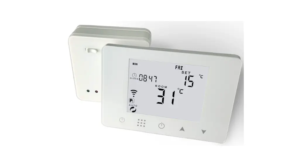
HY09RF WiFi Wireless Thermostat with RF Receiver
User Manual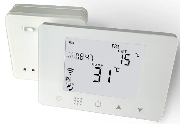 RF WIFI Wireless Thermostat User Manual
HY09RF WiFi Wireless Thermostat with RF Receiver
Search “Smart lift” app from Google play and app store and download it Choose one WIFI matching method of following 2:
- WIFI matching on thermostat:connect to voltage and turn on thermostat,long press for 3-5 seconds,when OFF,short press
 to match WIFI when WiFi and cloud icon are blinking together
 - WIFI matching on receiver:connect to voltage and turn on receiver,long press receiver “push” button to match WIFI,when blue light is blinking
Technical Data
☆ Power: Receiver:90-240Vac 50/60HZ
☆ Thermostat: USB power supply/4*AAA Batteries
☆ Pls remove batteries when USB power is working.
☆ Display accuracy: ±0.5°C
☆ Probe sensor: NTC(10k)1%
☆ Contact capacity: 5A/250V(WW);16A/250V(WE) ☆ Working environment temperature: 0~70°C ☆ Range of temperature adjustment: 5~35°C
☆ Insulating condition: Normal environment
☆ Running program: Set per 1 week as a cycle
☆ Output: Switch relay
☆ Installation: Wall mounted or on battery seat
☆ Size(mm):130*90*25
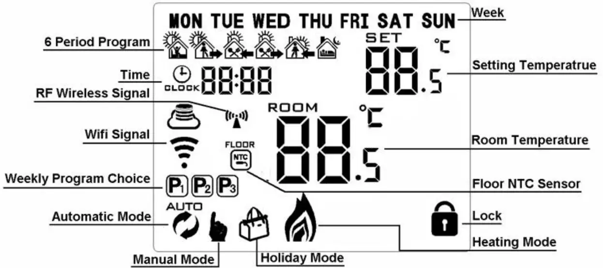
Home Screen
Quick Operaetion
| NO | Icon | Description |
| A |  | Turn ON/OFF |
| B | 1 Short press 2 Power on state, long press 3 Power off state, long pressv | |
| C | 1 Confirm key 2 Short press it to set time 3 Holiday mode setting. 4. Power off state,long press | |
| B | 1 Decrease key 2 Long press to lock /unlock | |
| D | 1 Increase key 2 Auto mode state, press 3 Long press to check external sensor temperature (only used for the receiver with external sensor) |
Time Setting
Power on state, press ![]() to set minute. Second press
to set minute. Second press![]() to set hour. Third press
to set hour. Third press![]() to set week.
to set week.
Press![]() ,
,![]() to change value. Press
to change value. Press![]() again to confirm.
again to confirm.
Holiday Mode Setting
Power on state, long press![]() for 3-5 seconds to do holiday mode setting. Press
for 3-5 seconds to do holiday mode setting. Press ![]() ,or
,or ![]() to change “OFF” to “ON”. Then press
to change “OFF” to “ON”. Then press ![]() to switch days and temperature, press
to switch days and temperature, press ![]() ,
,![]() to change value. Press
to change value. Press ![]() again to confirm. If you want to close holiday mode, press
again to confirm. If you want to close holiday mode, press![]()
Programmable Mode Setting
6 times period setting: 5+2 days(factory default),6+1 days, 7 days
Long press “ ![]() ” 3-5 seconds to do Programmable Mode Setting . Short press “
” 3-5 seconds to do Programmable Mode Setting . Short press “![]() ” to switch and confirm. Press “
” to switch and confirm. Press “![]() and “
and “![]() ” to adjust value.
” to adjust value.
Power on state, long press “ ![]() ” 3-5 seconds to enter into first time period then set hour. press “
” 3-5 seconds to enter into first time period then set hour. press “![]() and “
and “![]() ” to adjust hour, short press “
” to adjust hour, short press “ ![]() ” to confirm then set minutes, press “ “
” to confirm then set minutes, press “ “![]() and “
and “![]() ” to adjust minutes, press “
” to adjust minutes, press “ ![]() ” to confirm then enter into temperature setting, press “
” to confirm then enter into temperature setting, press “![]() and “
and “![]() ” to adjust value. Pls follow the steps of first time period to set second time period, thirdly time period ……
” to adjust value. Pls follow the steps of first time period to set second time period, thirdly time period ……
After finish setting , stand for about 10 seconds ,it will save setting then exit .
| Wake up | Out door | Back home | Out door | Back home | Sleep | ||||||
| 6:00 | 21°C | 8:00 | 17°C | 11:00 | 21°C | 13:30 | 17°C | 17:00 | 21°C | 22:00 | 17°C |
Advanced Setting
Power off state, long press![]() for 3-5 seconds to do advanced setting. Short press “
for 3-5 seconds to do advanced setting. Short press “ ![]() ” to switch and confirm. Press “
” to switch and confirm. Press “ ![]() ” and “
” and “![]() ” to adjust options.
” to adjust options.
After finish setting , stand for about 10 seconds ,it will save setting then exit .
| NO | Setting Options | Data Setting Function | Factory Default |
| Al | Temp Calibration | -9-+9°C (display current temperature) | -1°C |
| A2 | Temp Tolerance of Built in Sensor | 0.5-5°C | 1°C |
| A3 | Temp Tolerance of External Sensor | 1-9°C | 2°C |
| A4 | Children Lock | 0:half lock 1:full lock | 0 |
| AS | High temperature protection | 1.20°C-70°C 2.When setting temp is lower than 35°C, screen displays [–] , cancel highest temp protection | 45°C |
| A6 | Low temperature protection (anti-freeze protection) | 1.1-10°C 2.When setting temp is higher than 10’C, screen display [–] , cancel anti freeze protection | 5°C |
| A7 | Min Temp Setting | 1-10°C | 5°C |
| A8 | Max Temp Setting | 20-70°C | 35°C |
| A9 | On Power memory function | 0:as last status 1 turn Off status 2 turn on status | 0 |
| ~a | Weekly Programmable Function | P1:5+2 days P2:6+1 days P3:7 days | P1 |
| AB | Factory defaults | Display A o, long press |
Setting IP code
Power off state, long press![]() for 3-5 seconds to do advanced setting. Short press “ ” to switch and confirm. Press “
for 3-5 seconds to do advanced setting. Short press “ ” to switch and confirm. Press “![]() ” and “
” and “![]() ” to adjust options.
” to adjust options.
After finish setting , standing for 10 seconds ,it will save setting then exit .
! Considering battery usage, RF data updates every 20 minutes. If you wanna shorten interval, pls use USB power and remove batteries. Follow B05, B06 operation.
| NO | Setting Options | Data Setting Function Factory | Default |
| B1 | IP code high setting | 00-FF | 0 |
| B2 | IP code low setting | 01-FF | 1 |
| B3 | Thermostat and receiver paired | Display”55″ means IP match successfully. (When receiver is power-on, and orange LED is on ,press thermostat | 0 |
| B4 | Sensor state | N1:single built-in sensor N3:both built-in sensor and external sensor. | N1 |
| B05 | Minute interval of RF transmission | 0-30 minutes | 20 min. |
| B06 | Second interval of RF transmission | 3-30 seconds(B5=0 IS availd) | 30 s |
When the setting value of B5 and B6 in the advanced option is less than or equal to 20 minutes, it is recommended to use the USB adapter to supply power. If the battery is used for power supply, the battery life will be greatly shortened.
Description of hysteresis: The factory initial high temperature protection is set to 45℃, and the high temperature protection hysteresis is set to 2. When the external sensor detects that the temperature rises above 45℃, the relay will stop output and the thermostat will send out a high temperature protection alarm; When the sensor detects that the temperature drops below 43°C, the relay will re-output and the alarm will be cancelled. (This function is valid when the relay has output) Please select the internal and external temperature sensor working mode correctly. If the selection is wrong or the sensor is faulty (damaged), the display interface will display “E1” or “E2”, and the thermostat will stop heating until the fault is eliminated.
Description of thermostat data communication:
- Under normal working conditions, communicate with the receiver every 20 minutes.
- Press the switch button to communicate with the receiver once.
- When the output status is switched, it will communicate with the receiver once.
 : Always on when wireless communication is normal, and flashing when wireless communication is abnormal.
Receiver Indicator Light
Power indicator (green): Always on after power-on, and off: green light on for 1 second and off for 1 second.
RF signal indicator (orange): always on within 10 seconds of power-on (at this time, the IP address of the thermostat can be sent to the receiver to complete the pairing: refer to the thermostat and receiver pairing options in the advanced options), the pairing is successful After that, the signal light will be off; or if there is no pairing action within 10 seconds, the light will also be automatically turned off; during normal work, the light will flash when a wireless signal is received.
Load/fault indicator (red): In normal operation, the load output is turned on, the light is on, and the load output is off, and the light is off; when there is a fault, it flashes to alarm, and the fault indication is as follows:
- The thermostat and the receiver are not paired: flashes 2 times (quick flashes), with an interval of 2 seconds off
- Loss of wireless signal (no data communication in 1 hour): flashes 3 times (quick flashes), with an interval of 2 seconds off
- External sensor alarm: flashes 4 times (fast flashes), with an interval of 2 seconds off
Note: Fault 3 is only valid when the sensor type is selected as N3 in the advanced options of the thermostat.
WIFI signal indicator (blue): When WIFI data is received, it will flash once; continuous fast flashing means it is in WIFI EZ network configuration mode; continuous slow flashing means it is in WIFI AP network configuration mode; it will be often after successful network configuration On for 2 seconds; when the WIFI is abnormal, it will flash twice quickly with an interval of 2 seconds off.
Wiring Diagram
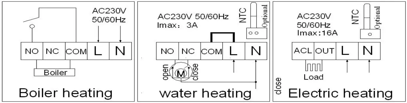
![]() RISK OF ELECTRICAL SHOCK
RISK OF ELECTRICAL SHOCK
Please arrange professional technician to install the product according to drawings and instructions.
Disconnect power supply before making any connection. Contact with components carrying hazardous voltage can cause electrical shock.


 Wireless Digital Thermostat User Manual")

 Wireless Digital Thermostat User Manual")
