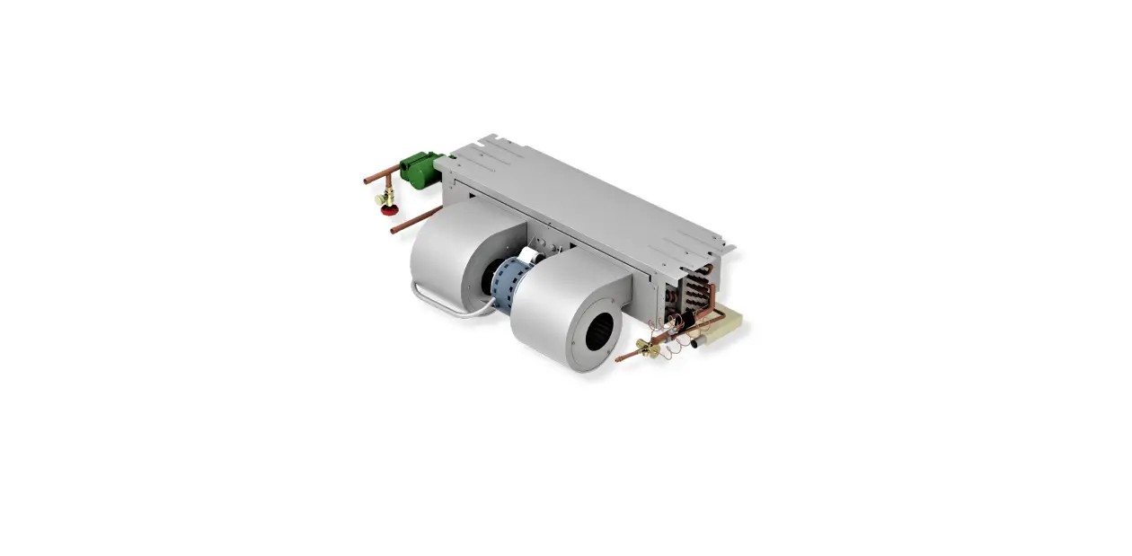
First Co CDX Series AquaTherm Ceiling Fan Coil
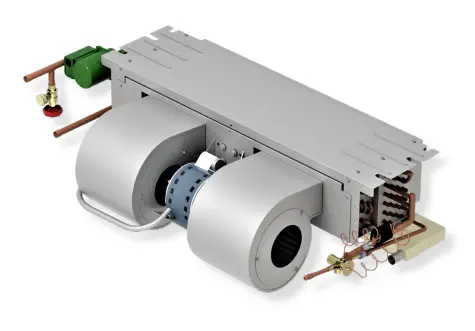
General description
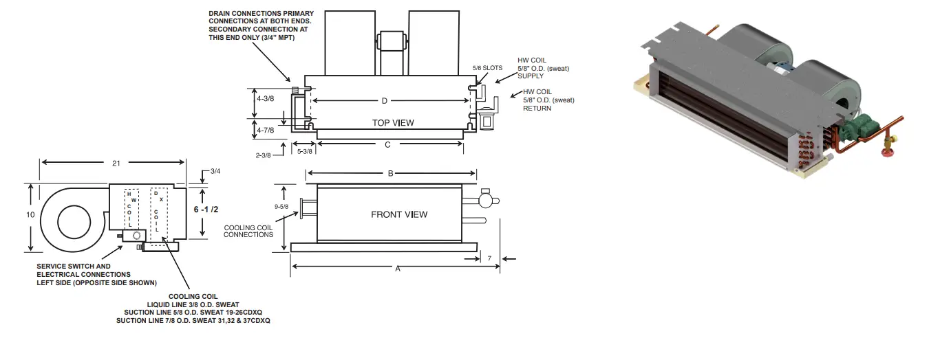
The space-saving CDX series fan coil is only 10” high (11” with enclosure), thus allowing it to recess in a ceiling. Recessed ceiling fan coils save valuable floor space and eliminate costly “equipment” closets. All CDX fan coils include a 120/24V transformer and are completely prewired. A sloped drain pan allows positive drainage of condensate. These fan coils are compatible with any source of hot water that doesn’t exceed 180º F and is NSF/ANSI certified for use with domestic water.
(1) First Co’s customer is ultimately responsible for confirming which fan coil models are compatible with selected outdoor unit(s) and which expansion valves (if any) are required. To determine certified indoor/outdoor matches, go to www.firstco.com or contact the factory.
STANDARD FEATURES
- Factory installed service switch
- Freeze protector on HW coil
- Freeze protector on the DX coil
- Two speed fan operation
- Drain pan has 3/4” NPT primary and secondary (overflow) fittings
- 120V motor, 24V controls
- Highly efficient copper tube/aluminum fin heating and cooling coils. Cooling coil has a piston-type metering device or factory or field installed R410A TXV’s (non-bleed type). Contact factory for correct match with outdoor unit.
- Insulated and coated galvanized steel drain pan is sloped for proper drainage
- Effective January 2016, Cabinet air leakage is no more than 2% when tested in accordance with ASHRAE 193.
OPTIONAL ACCESSORIES
- Attractive off-white return air / access panel with captive screws (panels can be field painted)
- IAQ filter panels (see P. 3)
- Fully insulated enclosure with matching ceiling panel (enclosure can be pre-installed). Also allows for ducted return air.
- Factory or field installed TXV’s (non-bleed type)
- Condensate overflow switch (field installed) (# SS3)
CIRCUIT BOARD FEATURES
WHEN B IS ADDED TO MODEL NUMBER
Multi-function microprocessor circuit board with:
- Automatic pump timer (heating mode) – purge mode (60 seconds every 6 hours)
- Blower-on fan delay (heating mode) – preheats the HW coil for 45 seconds.
- Blower-off fan delay (heating and cooling modes) blower continues to operate for 15 seconds after the thermostat is satisfied for increased efficiency.
MODEL NOMENCLATURE
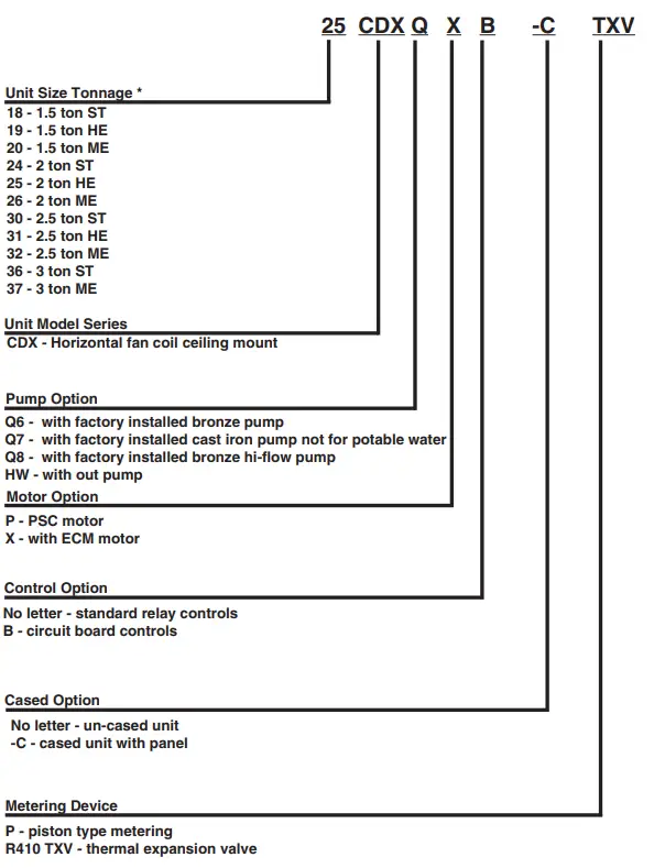
In keeping with its policy of continuous progress and product improvement, First Co. reserves the right to make changes without notice. Maintenance for all First Co. products is available under “Product Maintenance” at www.firstco.com.
- ST – standard coil
- HE – high efficiency coil
- ME – maximum efficiency coil
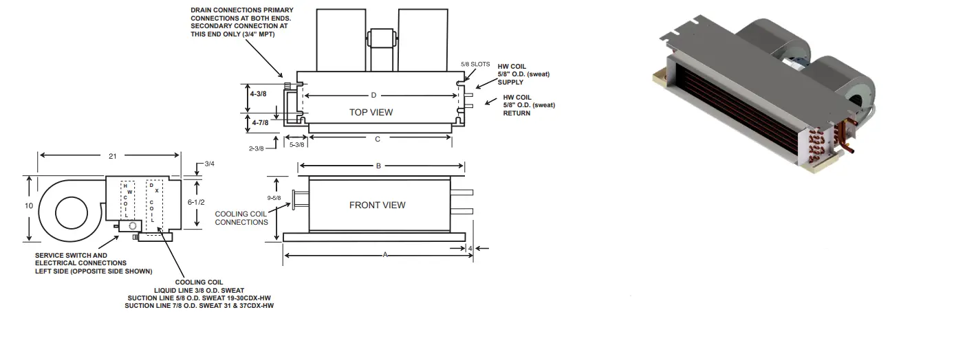
PHYSICAL DIMENSIONS
UNCASED VERSION NO PUMP
| PHYSICAL DIMENSIONS | ||||
| UNIT MODEL | A | B | C | D |
| 18/19CDX | 38-1/8 | 37-1/4 | 30-1/8 | 34-3/4 |
| 20/25CDX | 44-1/8 | 43-1/4 | 36-1/8 | 40-3/4 |
| 26/31CDX | 50-1/8 | 49-1/4 | 42-1/8 | 46-3/4 |
| 32/37CDX | 57-1/8 | 56-1/4 | 49-1/8 | 53-3/4 |
UNCASED VERSION WITH PUMP
| PHYSICAL DIMENSIONS | ||||
| UNIT MODEL | A | B | C | D |
| 18/19CDXQ* | 45-1/8 | 37-1/4 | 30-1/8 | 34-3/4 |
| 20-25CDXQ* | 51-1/8 | 43-1/4 | 36-1/8 | 40-3/4 |
| 26/31CDXQ* | 57-1/8 | 49-1/4 | 42-1/8 | 46-3/4 |
| 32/37CDXQ* | 64-1/8 | 56-1/4 | 49-1/8 | 53-3/4 |
CASED VERSION
KNOCKOUT FOR DUCTED RETURN Ducted return requires remote filter grille (field supplied) and non-louvered panel
| ENCLOSURE DIMENSIONS | PANEL NO. (STD.) | PANEL NO. (IAQ) | DESCRIPTION | CEILING PANEL OPENING | PANEL FRAME DIMS (OUTSIDE) | ||||||
| FOR MODEL | ENCLOSURE | A | B | C | (2) | W | L | W | L | ||
| 19CDX | 9ECDX01 (1) | 45-3/4 | 30-7/8 | 34 | 966 | 966-M8 | LOUVERED | 24-1/2 | 46 | 27-1/2 | 49 |
| 966-1 | NA | NON-LOUVERED | 24-1/2 | 46 | 27-1/2 | 49 | |||||
| 20/25CDX | 9ECDX02 (1) | 51-3/4 | 36-7/8 | 40 | 967 | 967-M8 | LOUVERED | 24-1/2 | 52-1/2 | 27-1/2 | 55-1/2 |
| 967-1 | NA | NON-LOUVERED | 24-1/2 | 52-1/2 | 27-1/2 | 55-1/2 | |||||
| 26/31CDX | 9ECDX03 (1) | 58-1/2 | 42-7/8 | 46-3/4 | 967-6 | 967-6-M8 | LOUVERED | 24-1/2 | 60 | 27-1/2 | 63 |
| 967-7 | NA | NON-LOUVERED | 24-1/2 | 60 | 27-1/2 | 63 | |||||
| 32/37CDX | 9ECDX04 (1) | 66-1/2 | 49-7/8 | 54-3/4 | 967-8 | 967-8-M8 | LOUVERED | 24-1/2 | 67 | 27-1/2 | 70 |
| 967-5 | NA | NON-LOUVERED | 24-1/2 | 67 | 27-1/2 | 70 | |||||
CEILING ACCESS PANELS
| CEILING ACCESS PANELS | |||||||
| FOR MODEL | PANELNO. (STD.) | PANELNO. (IAQ) | DESCRIPTION | CEILING PANEL OPEINING | PANEL FRAME DIMS (OUTSIDE) | ||
| 19CDX | 966 | 966-M8 | LOUVERED | 24-1/2 | 46 | 27-1/2 | 49 |
| 966-1 | NA | NON-LOUVERED | 24-1/2 | 46 | 27-1/2 | 49 | |
| 20/25CDX | 967 | 967-M8 | LOUVERED | 24-1/2 | 52-1/2 | 27-1/2 | 55-1/2 |
| 967-1 | NA | NON-LOUVERED | 24-1/2 | 52-1/2 | 27-1/2 | 55-1/2 | |
| 26/31CDX | 967-6 | 967-6-M8 | LOUVERED | 24-1/2 | 60 | 27-1/2 | 63 |
| 967-7 | NA | NON-LOUVERED | 24-1/2 | 60 | 27-1/2 | 63 | |
| 32/37CDX | 967-8 | 967-8-MA | LOUVERED | 24-1/2 | 67 | 27-1/2 | 70 |
| 967-5 | NA | NON-LOUVERED | 24-1/2 | 67 | 27-1/2 | 70 | |
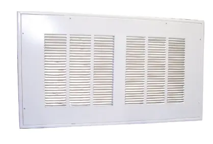
STANDARD PANELS
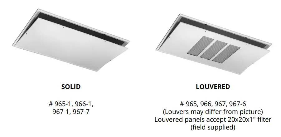
IAQ PANELS
# 966-M8, 967-M8 (accepts 2-20x20x1 filter) # 967-6-M8 (accepts 2-20x25x1 filter)
# 967-8-M8 (accepts 2-20x30x1 filter)
(GlasFloss ® Industries Series HV filter or equivalent is recommended)
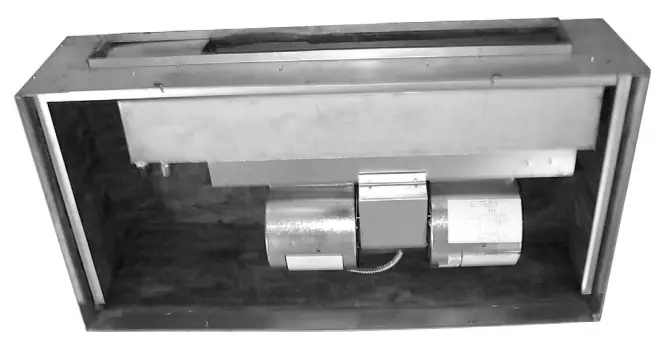
Picture shown is a “-C” model with installed CDX (Available from the factory as a complete unit)
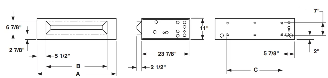
ENCLOSURE INSTALLATION SUPPORT FRAMING
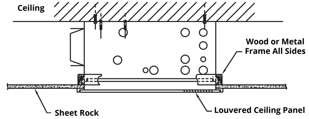
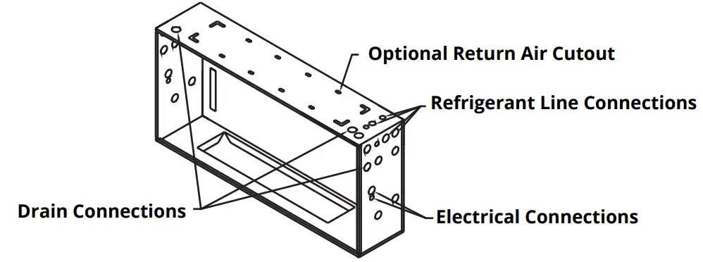
ENCLOSURE CONNECTION LOCATIONS
CDX Series – Without pump 1-1/2 THROUGH 3 TONS
PERFORMANCE DATA
| PERFORMANCE DATA CDX-HW | ||||||||
| UNIT MODEL | NOMINAL COOLING BTUH | PRESS. DROP (FT. WTR) | BTUH (1000) AT ENTERING WATER TEMPERATURE Delta -T 20ºF & GPM | |||||
| 120ºF | GPM | 140ºF | GPM | 180ºF | GPM | |||
| 19CDX-HW | 18,000 | 0.7 2.0 3.3 | 10.3 12.0 12.9 | 1.0 1.2 1.3 | 14.4 16.8 18.0 | 1.4 1.7 1.8 | 22.6 26.4 28.3 | 2.3 2.6 2.8 |
| 20CDX-HW | 18,000 | 0.8 2.1 4.1 | 10.9 12.9 13.7 | 1.1 1.3 1.4 | 15.3 18.0 19.2 | 1.5 1.8 1.9 | 24.0 28.3 30.2 | 2.4 2.8 3.0 |
| 25CDX-HW | 24,000 | 2.1 4.1 6.6 | 14.7 15.9 16.5 | 1.5 1.6 1.7 | 20.6 22.2 23.1 | 2.1 2.2 2.3 | 32.4 34.9 36.3 | 3.2 3.5 3.6 |
| 26CDX-HW | 24,000 | 2.2 4.3 6.8 | 15.7 17.0 17.6 | 1.6 1.7 1.8 | 22.0 23.8 24.7 | 2.2 2.4 2.5 | 34.6 37.4 38.8 | 3.5 3.7 3.9 |
| 31CDX-HW | 30,000 | 2.2 4.3 6.8 | 17.3 18.8 19.6 | 1.7 1.9 2.0 | 24.2 26.3 27.5 | 2.4 2.6 2.8 | 38.0 41.3 43.2 | 3.8 4.1 4.3 |
| 32CDX-HW | 30,000 | 2.8 5.4 8.5 | 18.4 20.1 21.1 | 1.8 2.0 2.1 | 25.8 28.2 29.5 | 2.6 2.8 3.0 | 40.5 44.3 46.4 | 4.1 4.4 4.6 |
| 37CDX-HW | 36,000 | 2.8 5.4 8.5 | 19.7 21.7 22.8 | 2.0 2.2 2.3 | 27.6 30.4 31.9 | 2.8 3.0 3.2 | 43.4 47.8 50.1 | 4.3 4.8 5.0 |
| PERFORMANCE DATA CDXX-HW | ||||||||
| UNIT MODEL | NOMINAL COOLING BTUH | PRESS. DROP (FT. WTR) | BTUH (1000) AT ENTERING WATER TEMPERATURE Delta-T-20ºF & GPM | |||||
| 120ºF | GPM | 140ºF | GPM | 180ºF | GPM | |||
| 12CDXX-HW | 12,000 | 0.7 2.0 3.3 | 8.4 9.6 10.1 | 0.1 1.0 1.0 | 11.7 13.4 14.2 | 1.2 1.3 1.4 | 18.4 21.1 22.4 | 1.8 2.1 2.2 |
| 19CDXX-HW | 18,000 | 0.7 2.0 3.3 | 10.3 12.0 12.9 | 1.0 1.2 1.3 | 14.4 16.8 18.0 | 1.4 1.7 1.8 | 22.6 26.4 28.3 | 2.3 2.6 2.8 |
| 20CDXX-HW | 18,000 | 0.8 2.1 4.1 | 10.9 12.9 13.7 | 1.1 1.3 1.4 | 15.3 18.0 19.2 | 1.5 1.8 1.9 | 24.0 28.3 30.2 | 2.4 2.8 3.0 |
| 25CDXX-HW | 24,000 | 2.1 4.1 6.6 | 14.7 15.9 16.5 | 1.5 1.6 1.7 | 20.6 22.2 23.1 | 2.1 2.2 2.3 | 32.4 34.9 36.3 | 3.2 3.5 3.6 |
| 26CDXX-HW | 24,000 | 2.2 4.3 6.8 | 15.7 17.0 17.6 | 1.7 1.9 2.0 | 22.0 23.8 24.7 | 2.4 2.6 2.8 | 34.6 37.4 38.8 | 3.8 4.1 4.3 |
| 31CDXX-HW | 30,000 | 2.2 4.3 6.8 | 17.3 18.8 19.6 | 1.7 1.9 2.0 | 24.2 26.3 27.5 | 2.4 2.6 2.8 | 38.0 41.3 43.2 | 3.8 4.1 4.3 |
| 32CDXX-HW | 30,000 | 2.8 5.4 8.5 | 18.4 20.1 21.1 | 1.8 2.0 2.1 | 25.8 28.2 29.5 | 2.6 2.8 3.0 | 40.5 44.3 46.4 | 4.1 4.4 4.6 |
| 37CDXX-HW | 36,000 | 2.8 5.4 8.5 | 19.7 21.7 22.8 | 2.0 2.2 2.3 | 27.6 30.4 31.9 | 2.8 3.0 3.2 | 43.4 47.8 50.1 | 4.3 4.8 5.0 |
NOTES:
- Heat BTUH is at 70º F EAT.
- Based on 20ºF Delta – T. Velocity not to exceed 4ft./sec.
- 120 degree and 180 degree data is supplied for boiler applications.
- Heating BTUH output will not exceed output of water heater.
- Approved for installation with 0″ clearance to combustible material.
- Use the capacities when First Co. “Flow Control Module” is used (# 940-3CV)
- Freeze protection standard on hot water and DX coils.
CDX Series – Without pump 1-1/2 THROUGH 3 TONS
PERFORMANCE DATA
| PERFORMANCE DATA CDXQ | ||||||||||
| UNIT MODEL | NOMINAL COOLING BTUH | PRESS. DROP (FT. WTR) | BTUH (1000) AT ENTERING WATER TEMPERATURE Delta-T 20ºF & GPM | |||||||
| 120ºF | GPM | 130ºF | GPM | 140ºF | GPM | 180ºF | GPM | |||
| 19CDXQ* | 18,000 | 3.3 | 12.9 | 1.3 | 15.4 | 1.5 | 18.0 | 1.8 | 28.3 | 2.8 |
| 20CDXQ* | 18,000 | 4.1 | 13.7 | 1.4 | 16.5 | 1.7 | 19.2 | 1.9 | 30.2 | 3.0 |
| 24/25CDXQ* | 24,000 | 4.1 | 15.9 | 1.6 | 19.0 | 1.9 | 22.2 | 2.2 | 34.9 | 3.5 |
| 26CDXQ* | 24,000 | 4.3 | 17.0 | 1.7 | 20.4 | 2.0 | 23.8 | 2.4 | 37.4 | 3.7 |
| 31CDXQ* | 30,000 | 4.3 | 18.8 | 1.9 | 22.5 | 2.3 | 26.3 | 2.6 | 41.3 | 4.1 |
| 32CDXQ* | 30,000 | 5.4 | 20.1 | 2.0 | 24.2 | 2.4 | 28.2 | 2.8 | 44.3 | 4.4 |
| 37CDXQ* | 36,000 | 5.4 | 21.7 | 2.2 | 26.1 | 2.6 | 30.4 | 3.0 | 47.8 | 4.8 |
| PERFORMANCE DATA CDXQX | ||||||||||
| UNIT MODEL | NOMINAL COOLING BTUH | PRESS. DROP (FT. WTR) | BTUH (1000) AT ENTERING WATER TEMPERATURE Delta-T 20ºF & GPM | |||||||
| 120ºF | GPM | 130ºF | GPM | 140ºF | GPM | 180ºF | GPM | |||
| 12CDXQ*X | 12,000 | 3.3 | 10.1 | 1.0 | 12.2 | 1.2 | 14.2 | 1.4 | 22.4 | 2.2 |
| 19CDXQ*X | 18,000 | 3.3 | 12.9 | 1.3 | 15.4 | 1.5 | 18.0 | 1.8 | 28.3 | 2.8 |
| 20CDXQ*X | 18,000 | 4.1 | 13.7 | 1.4 | 16.5 | 1.7 | 19.2 | 1.9 | 30.2 | 3.0 |
| 25CDXQ*X | 24,000 | 4.1 | 15.9 | 1.6 | 19.0 | 1.9 | 22.2 | 2.2 | 34.9 | 3.5 |
| 26CDXQ*X | 24,000 | 4.3 | 17.0 | 1.7 | 20.4 | 2.0 | 23.8 | 2.4 | 37.4 | 3.7 |
| 31CDXQ*X | 30,000 | 4.3 | 18.8 | 1.9 | 22.5 | 2.3 | 26.3 | 2.6 | 41.3 | 4.1 |
| 32CDXQ*X | 30,000 | 5.4 | 20.1 | 2.0 | 24.2 | 2.4 | 28.2 | 2.8 | 44.3 | 4.4 |
| 37CDXQ*X | 36,000 | 5.4 | 21.7 | 2.2 | 26.1 | 2.6 | 30.4 | 3.0 | 47.8 | 4.8 |
NOTES:
- Heat BTUH is at 70º F EAT.
- 120º F and 180º F data is supplied for boiler applications.
- Heating BTUH output will not exceed output of water heater.
- Approved for installation with 0″ clearance to combustible material.
- Freeze protection on hot water and DX coils.
- Based on 20º Delta-T,Velocity not to exceed 4ft./sec.
CDX Series 1-1/2 THROUGH 3 TONS
BLOWER DATA
| BLOWER DATA WITH PSC MOTOR | |||||||||||||
| UNIT MODEL | MOTOR (1) | MOTOR HP (120V) | MIN. CKT. AMPACITY (120V) | MAX. CKT. PROTECTION | CFM vs. EXTERNAL STATIC PRESSURE (3) | ||||||||
| RPM | AMPS | 0.05 | 0.10 | 0.15 | 0.20 | 0.25 | 0.30 | 0.35 | 0.40 | ||||
| 19/20CDX | 1550 | 2.3 | 1/5 | 3 | 15 | 710 | 680 | 650 | 620 | 590 | 560 | 530 | 500 |
| 25/26CDX | 1550 | 3.6 | 1/4 | 5 | 15 | 880 | 840 | 800 | 760 | 720 | 680 | 640 | 600 |
| 31CDX | 1550 | 4.6 | 1/5 | 6 | 15 | 1100 | 1060 | 1020 | 980 | 930 | 880 | 830 | 780 |
| 32CDX | 1550 | 4.6 | 1/5 | 6 | 15 | 1160 | 1130 | 1095 | 1060 | 1025 | 990 | 950 | 910 |
| 37CDX | 1550 | 4.6 | 1/5 | 6 | 15 | 1310 | 1260 | 1210 | 1160 | 1110 | 1060 | 1000 | 940 |
NOTES:
- Units should not be applied to a system with less than 350 CFM/Ton airflow.
- Motors are 120V and operate on high speed for cool and low speed for heating.
- CFM vs. static at high motor speed.
- Add .05 static when enclosure and/or ceiling panel are used.
- 31, 32 and 37 CDX-HW have two motors and four blowers.
| BLOWER DATA WITH ECM MOTOR | ||||||||||||
| UNIT MODEL | MOTOR HP | SPEED TAP | TAP COLOR | BHP | MOTOR AMPS | CFM vs. EXTERNAL STATIC PRESSURE | ||||||
| 0.10 | 0.15 | 0.20 | 0.25 | 0.30 | 0.35 | 0.40 | ||||||
| 12CDXX-HW | 1/7 | OPTIONAL HIGH | GREEN | 0.08 | 1.3 | 565 | 545 | 525 | 505 | 485 | 470 | 450 |
| STD. HIGH | ORANGE | 0.06 | 1.0 | 485 | 460 | 440 | 420 | 400 | 385 | 365 | ||
| STD. LOW | YELLOW | 0.04 | 0.5 | 300 | 275 | 250 | 225 | 205 | 185 | — | ||
| 19/20CDXX-HW | 1/2 | OPTIONAL HIGH | GREEN | 0.22 | 2.8 | 760 | 745 | 730 | 715 | 700 | 685 | 670 |
| STD. HIGH | ORANGE | 0.17 | 2.1 | 670 | 650 | 630 | 615 | 600 | 588 | 570 | ||
| STD. LOW | YELLOW | 0.14 | 1.6 | 570 | 555 | 540 | 520 | 500 | 480 | — | ||
| 25/26CDXX-HW | 1/2 | OPTIONAL HIGH | GREEN | 0.30 | 3.8 | 980 | 960 | 940 | 920 | 900 | 875 | 850 |
| STD. HIGH | ORANGE | 0.25 | 3.0 | 890 | 870 | 850 | 830 | 810 | 790 | 770 | ||
| STD. LOW | YELLOW | 0.21 | 2.5 | 800 | 775 | 750 | 725 | 700 | 675 | — | ||
| 31CDXX-HW | 1/2 | OPTIONAL HIGH | WHITE | 0.40 | 4.7 | 1160 | 1145 | 1130 | 1115 | 1100 | 1080 | 1060 |
| STD. HIGH | GREEN | 0.33 | 3.8 | 1060 | 1040 | 1020 | 1005 | 990 | 975 | 960 | ||
| OPTIONAL MED | ORANGE | 0.28 | 3.2 | 970 | 955 | 940 | 920 | 900 | 880 | 860 | ||
| STD. LOW | YELLOW | 0.23 | 2.6 | 870 | 850 | 830 | 810 | 790 | 770 | — | ||
| 32CDXX-HW | 1/2 | OPTIONAL HIGH | WHITE | 0.39 | 4.8 | 1220 | 1200 | 1180 | 1155 | 1125 | 1095 | 1065 |
| STD. HIGH | GREEN | 0.27 | 3.2 | 1030 | 1005 | 985 | 960 | 940 | 920 | 900 | ||
| STD. LOW | ORANGE | 0.22 | 2.5 | 905 | 885 | 860 | 840 | 820 | 800 | — | ||
| OPTIONAL LOW | YELLOW | 0.16 | 1.8 | 725 | 705 | 685 | 670 | 650 | 630 | — | ||
| 37CDXX-HW | 1/2 (2) | OPTIONAL HIGH | WHITE | 0.45 | 5.6 | 1380 | 1360 | 1340 | 1320 | 1300 | 1280 | 1260 |
| STD. HIGH | GREEN | 0.38 | 4.7 | 1290 | 1270 | 1250 | 1225 | 1200 | 1175 | 1150 | ||
| STD. LOW | ORANGE | 0.31 | 3.7 | 1130 | 1105 | 1080 | 1055 | 1030 | 1010 | — | ||
NOTES:
- Units should not be applied to a system with less than 350 CFM/Ton airflow.
- Shaded speeds are factory settings.
- Add .05 static when enclosure and/or ceiling panel are used.
- 37 CDXX have two motors and four blowers.
CDX Series – Without pump 1-1/2 THROUGH 3 TONS
ELECTRICAL DATA
| ELECTRICAL DATA WITH PSC MOTOR | |||||
| UNIT MODEL | MOTOR (1) | MOTOR HP (120V) | MIN. CKT. AMPACITY (120V) | MAX. CKT. PROTECTION | |
| RPM | AMPS | ||||
| 19/20CDX-HW | 1550 | 2.3 | 1/5 | 3 | 15 |
| 25/26CDX-HW | 1550 | 3.6 | 1/4 | 5 | 15 |
| 31CDX-HW | 1550 | 4.6 | 1/5 | 6 | 15 |
| 32CDX-HW | 1550 | 4.6 | 1/5 | 6 | 15 |
| 37CDX-HW | 1550 | 4.6 | 1/5 | 6 | 15 |
| ELECTRICAL DATA WITH ECM MOTOR | ||||
| UNIT MODEL | MOTOR HP | AMPS | MIN. CIR AMPACITY | MAX CIR PROTECTION |
| MOTOR | ||||
| 12CDXX-HW | 1/7 | 2.0 | 3 | 15 |
| 19/20CDXX-HW | 1/2 | 7.0 | 9 | 15 |
| 25/26CDXX-HW | 1/2 | 7.0 | 9 | 15 |
| 31CDXX-HW | 1/2 | 7.0 | 9 | 15 |
| 32CDXX-HW | 1/2 | 7.0 | 9 | 15 |
| 37CDXX-HW | 1/2 (2) | 7.0 | 16 | 20 |
CDX Series – With pump 1-1/2 THROUGH 3 TONS
ELECTRICAL DATA
| ELECTRICAL DATA WITH PSC MOTOR STANDARD PUMP | |||||
| UNIT MODEL | MOTOR HP (120V) | AMPS (120V) | MIN. CIR AMPACITY | MAX CIR PROTECTION | |
| MOTOR | PUMP | ||||
| 19/20CDXQ* | 1/5 | 2.3 | 0.57 | 4 | 15 |
| 24CDXQ* | 1/5 | 3.0 | 0.57 | 5 | 15 |
| 25/26CDXQ* | 1/4 | 3.6 | 0.57 | 6 | 15 |
| 31CDXQ* | 1/5 | 4.6 | 0.57 | 7 | 15 |
| 32CDXQ* | 1/5 | 4.6 | 0.57 | 7 | 15 |
| 37CDXQ* | 1/5 | 4.6 | 0.57 | 7 | 15 |
| ELECTRICAL DATA WITH PSC MOTOR AND UPGRADED PUMP | |||||
| UNIT MODEL | MOTOR HP (120V) | AMPS (120V) | MIN. CIR AMPACITY | MAX CIR PROTECTION | |
| MOTOR | PUMP | ||||
| 19/20CDXQ* | 1/5 | 2.3 | 0.84 | 4 | 15 |
| 25/26CDXQ* | 1/4 | 3.6 | 0.84 | 6 | 15 |
| 31CDXQ* | 1/5 (2) | 4.6 | 0.84 | 7 | 15 |
| 32CDXQ* | 1/5 (2) | 4.6 | 0.84 | 7 | 15 |
| 37CDXQ* | 1/5 (2) | 4.6 | 0.84 | 7 | 15 |
| ELECTRICAL DATA WITH ECM MOTOR AND STANDARD PUMP | |||||
| UNIT MODEL | MOTOR HP | AMPS | MIN. CIR AMPACITY | MAX CIR PROTECTION | |
| MOTOR | PUMP | ||||
| 12CDXQ*X | 1/7 | 2.0 | 0.57 | 4 | 15 |
| 19/20CDXQ*X | 1/2 | 7.0 | 0.57 | 10 | 15 |
| 25/26CDXQ*X | 1/2 | 7.0 | 0.57 | 10 | 15 |
| 31CDXQ*X | 1/2 | 7.0 | 0.57 | 10 | 15 |
| 32CDXQ*X | 1/2 | 7.0 | 0.57 | 10 | 15 |
| 37CDXQ*X | 1/2 (2) | 7.0 | 0.57 | 17 | 20 |
| ELECTRICAL DATA WITH ECM MOTOR AND UPGRADED PUMP | |||||
| UNIT MODEL | MOTOR HP | AMPS | MIN. CIR AMPACITY | MAX CIR PROTECTION | |
| MOTOR | PUMP | ||||
| 12CDXQ*X | 1/7 | 2.0 | .84 | 4 | 15 |
| 19/20CDXQ*X | 1/2 | 7.0 | .84 | 10 | 15 |
| 25/26CDXQ*X | 1/2 | 7.0 | .84 | 10 | 15 |
| 31CDXQ*X | 1/2 | 7.0 | .84 | 10 | 15 |
| 32CDXQ*X | 1/2 | 7.0 | .84 | 10 | 15 |
| 37CDXQ*X | 1/2 (2) | 7.0 | .84 | 17 | 20 |
GUIDE SPECIFICATIONS
UNIT
All fan coils are manufactured with 20 to 22-gauge galvanized steel to resist corrosion. All units are approved for installation with “0” clearance to combustible material. Piping, drain, and wiring connections are readily accessible and mounting holes and/or slots are predrilled to save installation time and field labor expense. Exposed units and/or panels have a baked-on powder coat finish.
COILS
Coils have 3/8” O.D. copper tubing expanded to high-efficiency aluminum fins. Each Coil is factory tested to 450 psig.
DRAIN PANS
Drain pan is made from heavy gauge galvanized steel with “ folded corner joints” Drain pan is insulated with a U.L. Listed closed cell fire retardant foam insulation to prevent sweating.
BLOWER ASSEMBLIES
All blower wheels are centrifugal, forward curved, and dynamically balanced for smooth, quiet operation. Blower assemblies can be easily removed for service.
MOTORS
Standard motors are PSC type with internal thermal overload protection. Motors have permanently lubricated sleeve bearings for long life. All motors are resiliently mounted with rubber bushings to assure quiet, vibration-free operation and are easily removed. Ecm motors should have multi-speed connections or speed jumper changes. Motors have permanently lubricated sleeve bearings for long life. All motors are resiliently mounted with rubber bushings to assure quiet, vibration-free operation and are easily removed.
Water coils and pumps shall be NSF/ASNI 169:2016 certified for public health and should contain less than 2% lead. All water coils should have a check valve internal to the pump and have a air purge valve factory installed.


 Fan Coil Units Instructions")


