![]()
POWER COMMANDER 6
Installation Guide for: PC6-22091
Model coverage: 2002-2009 Yamaha XV1700 Road Star Warrior
PARTS LIST
1 POWER COMMANDER 6
1 INSTALLATION GUIDE
1 USB CABLE
2 DYNOJET DECALS
2 POWER COMMANDER DECALS
2 VELCRO STRIPS
1 ALCOHOL SWAB
PLEASE READ ALL DIRECTIONS BEFORE STARTING INSTALLATION.
THE IGNITION MUST BE TURNED OFF BEFORE INSTALLATION.
PC6-22091.01
INPUT ACCESSORY GUIDE
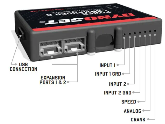
OPTIONAL ACCESSORY INPUTS
Map
(Input 1 or 2) The PC6 has the ability to hold 2 different base maps. You can switch on the fly between these two base maps when you hook up a switch to the MAP inputs. You can use any open/close type switch. The polarity of the wires is not important.
Shifter (Input 1 or 2) Used for clutch-less full throttle upshifts. Insert the wires from the Dynojet quick shifter into either Input 1 or Input 2. The polarity of the wires is not important. Set to Input 2 by default.
Speed
Not needed on Harley applications as the speed signal wire is built into the main wiring harness of the PC6.
Analog
This input is for a 0-5v signal such as engine temp, boost, etc. Once this input is established you can alter your fuel curve based on this input in the Power Core software.
Launch
You can connect a wire to either Input 1 or Input 2 and then the other end to a switch. This switch when engaged (continuity) will only allow the RPM to be raised to a certain limit (set in the software). When released, you will have full RPM.
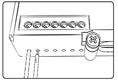
WIRE CONNECTIONS
To input wires into the PC6 first remove the rubber plug on the backside of the unit and loosen the screw for the corresponding input. Using a 22-24 gauge wire, strip about 10mm from its end. Push the wire into the hole of the PC6 until it stops and then tighten the screw. Make sure to reinstall the rubber plug.
NOTE: If you tin the wires with solder it will make inserting them easier.
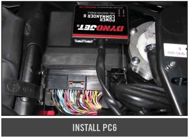
INSTALLING THE POWER COMMANDER 6
- Remove the seat. Remove the two nuts at the rear of the fuel tank.
- Remove the left hand cosmetic cover (chrome triangle cover that looks like an airbox).
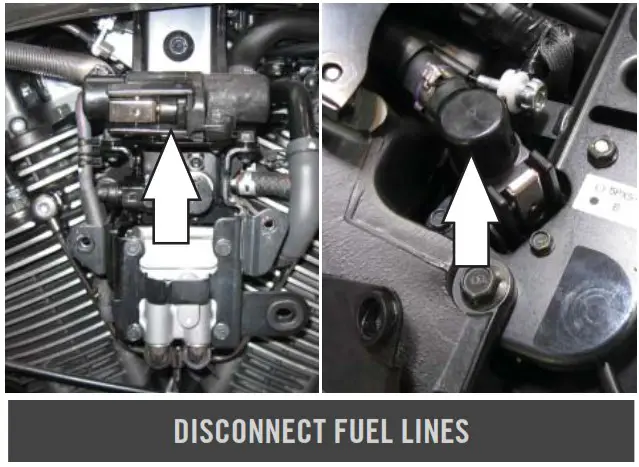
- To remove the fuel tank release the two drybreaks.
Do not cut the metal bands around the fuel lines to remove. - Remove the fuel tank.

- Remove the airbox.
To remove, unscrew the two bolts. Also loosen the clamp screw at the intake snorkel. To access this screw go in from the top of the bike on the inside of the frame.
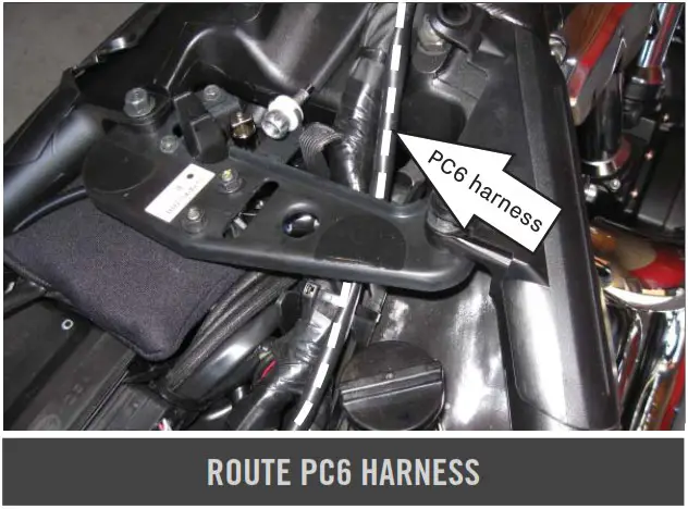
- Route the wires from the PC6 from the under the frame bracket towards the airbox.
Route the wires along the frame using the stock wire wraps.
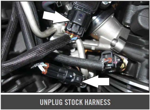
- Unplug the BLACK 4-pin connector for the fuel injectors.
- Unplug the BLACK 3-pin connector for the Throttle Position Sensor.

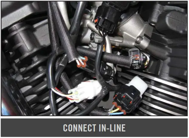
- Plug the connectors from the PC6 in-line of the stock wiring harness.

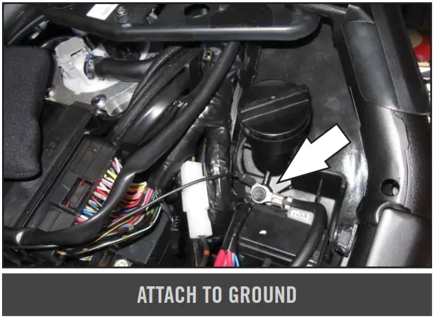
- Locate the stock ground. Follow the negative battery cable to the frame. Remove the allen bolt that secures the ground cable to the frame. Reinstall the allen bolt thru the stock ground cable, then thru the ground wire from the PC6 into the frame.

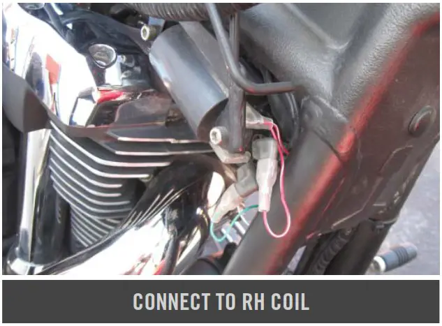
- Plug the pair of RED/WHITE wires on the PC6 wiring harness in-line of the right side Ignition Coil and the stock BLACK/RED wire.
- Plug the GREEN wire of the PC6 to the stock BLACK/WHITE wire and plug the WHITE/GREEN wire of the PC6 to the right side Ignition Coil.

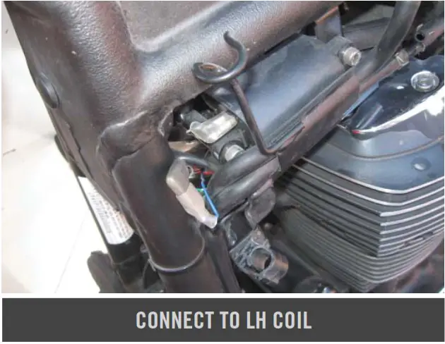
- On the left side Ignition Coil at the front of the bike, unplug the stock BLACK/ORANGE wire from the Ignition Coil.
- Plug the BLUE wire of the PC6 directly to the stock BLACK/ORANGE wire and the WHITE/BLUE wire of the PC6 directly to the Ignition Coil.

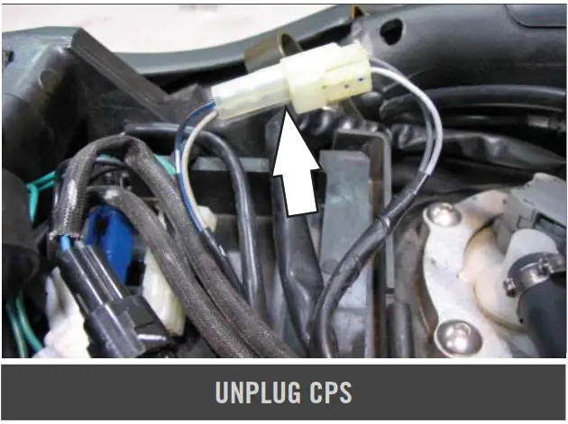
- Remove the rubber strap that holds the ECU in place and move the ECU to the side to gain access to the Crank Position Sensor connectors. This connector pair is clear and has LIGHT GREY and GREY colored wires going to it from the left side engine cover.
- Unplug the stock Crank Position Sensor connectors.

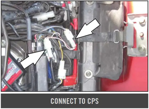
- Plug the pair of connectors from the PC6 with BROWN colored wires in-line of the stock Crank Position Sensor connectors.
- Reinstall the bike’s ECU back into its original location.
- Using the supplied Velcro, attach the PC6 to the top of the ECU. Use the alcohol swab to clean both surfaces before attaching.
- Reinstall the cover, fuel tank, and seats.


Download the latest map files from our web site at dynojet.com/tunes.
Optional Inputs:
Speed input – WHITE/YELLOW wire of WHITE 3 pin plug. Located under ECU (WHITE/YELLOW – BLUE BLUE/BLACK) 12v source for Autoune – BLUE wire of 6 pin connector for tail light. Located under the ECU
PUSH THE LIMIT
2191 MENDENHALL DRIVE, NORTH LAS VEGAS, NV 89081 – 800-992-4993 – DYNOJET.COM
© 2007-2022 DYNOJET RESEARCH ALL RIGHTS RESERVED


