
![]() PC6-22065 Power Commander 6
PC6-22065 Power Commander 6
Installation Guide
Install guide for PC6-22065
Model coverage:
2015-2017 Yamaha FZ-07
2018-2020 Yamaha MT-07
PARTS LIST
- 1 POWER COMMANDER 6
- 1 INSTALLATION GUIDE
- 1 USB CABLE
- 2 DYNOJET DECALS
- 2 POWER COMMANDER DECALS
- 3 VELCRO STRIPS
- 1 ALCOHOL SWAB
PLEASE READ ALL DIRECTIONS BEFORE STARTING INSTALLATION.
THE IGNITION MUST BE TURNED OFF BEFORE INSTALLATION.
INPUT ACCESSORY GUIDE
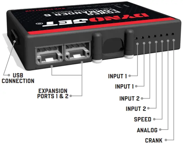
OPTIONAL ACCESSORY INPUTS
| Map | (Input 1 or 2) The PC6 has the ability to hold 2 different base maps. You can switch on the fly between these two base maps when you hook up a switch to the MAP inputs. You can use any open/close type switch. The polarity of the wires is not important. |
| Shifter | (Input 1 or 2) Used for clutch-less full-throttle upshifts. Insert the wires from the Dynojet quick shifter into either Input 1 or Input 2. The polarity of the wires is not important. Set to Input 2 by default. |
| Speed | If your application has a speed sensor then you can tap into the signal side of the sensor and run a wire into this input. This will allow you to calculate gear position in the Control Center Software. Once gear position is set up you can alter your map based on gear position and setup gear-dependent kill times when using a quick-shifter. |
| Analog | This input is for a 0-5v signal such as engine temp, boost, etc. Once this input is established you can alter your fuel curve based on this input in the Power Core software. |
| Launch | You can connect a wire to either Input 1 or Input 2 and then the other end to a switch. This switch when engaged (continuity) will only allow the RPM to be raised to a certain limit (set in the software). When released, you will have full RPM. |
WIRE CONNECTIONS
To input wires into the PC6 first remove the rubber plug on the backside of the unit and loosen the screw for the corresponding input. Using a 22-24 gauge wire, strip about 10mm from its end. Push the wire into the hole of the PC6 until it stops and then tighten the screw. Make sure to reinstall the rubber plug.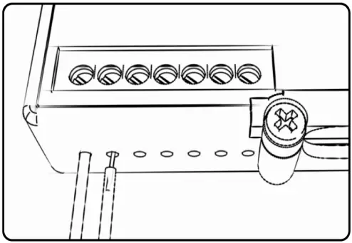 NOTE: If you tin the wires with solder it will make inserting them easier.
INSTALLING THE POWER COMMANDER 6
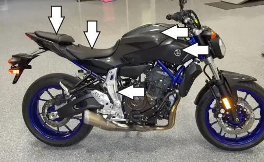 | 1. Remove both seats, both side panels, the bodywork surrounding the fuel tank, the panel between the seats, and the plastic panel above the right foot peg. 2. Remove the fuel tank. |
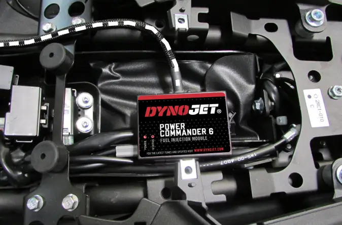 | 3. Store the PC6 module in the tail section beneath the passenger seat (tool kit area). The supplied Velcro strips can be used to secure the module. Clean both surfaces with the supplied alcohol swab prior to applying the Velcro adhesive. 4. Route the PC6 wiring harness forward along the right side frame rail. |
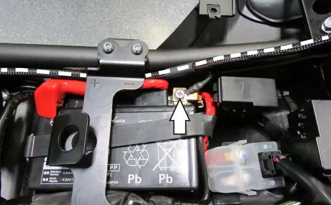 | 5. Secure the PC6 ground wire with the small ring lug to the negative (-) terminal of the bike’s battery. 6. Continue routing the wiring harness forward and towards the throttle bodies. |
 | 7. Unplug the stock wiring harness from both Fuel Injectors. |
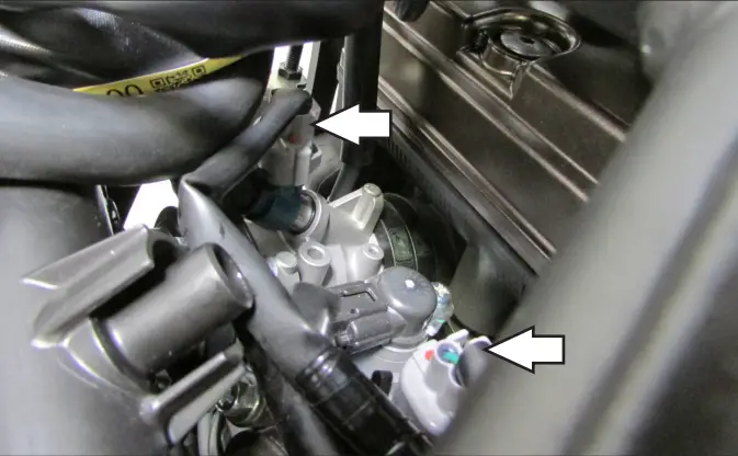
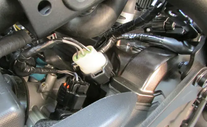
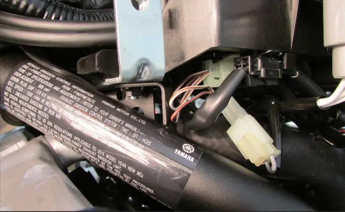
 | 8. Plug the PC6 wiring harness in line with the Fuel Injectors and the stock wiring harness. The pair of PC6 leads with ORANGE colored wires go to the left cylinder injector (#1), and the pair with YELLOW colored wires go to the right cylinder (#2). Only the right cylinder injector connections can be seen in this image. |
 | 9. Unplug the stock wiring harness from the Throttle Position Sensor located on the right side of the throttle bodies. |
 | 10. Plug the PC6 wiring harness in-line with the TPS and the stock wiring harness. 11. Route the rest of the PC6 wiring harness forward toward the top of the engine where the Ignition Coils are located. |
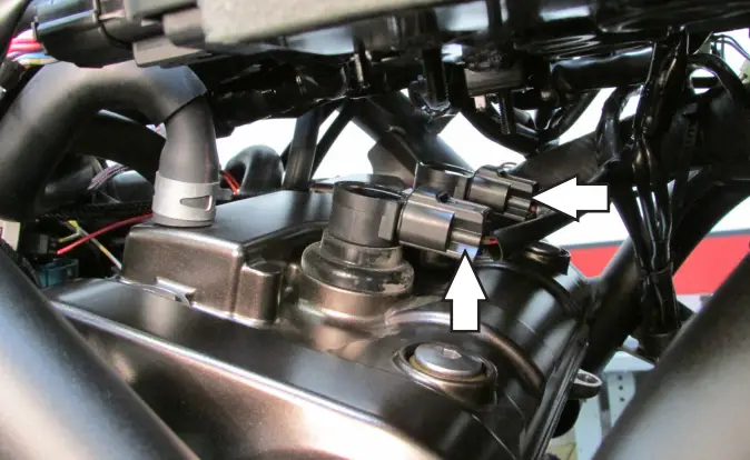 | 12. Unplug the stock wiring harness from both of the Ignition Coils. |
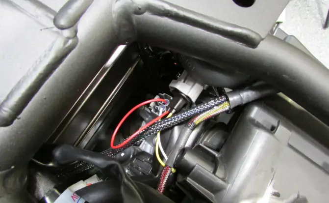
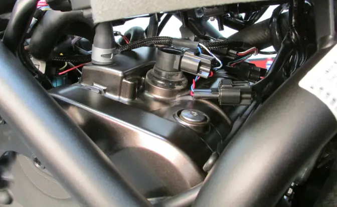 | 13. Plug the PC6 wiring harness in line with the Ignition Coils and the stock wiring harness. The pair of PC6 leads with GREEN-colored wires go to the left cylinder coil stick (#1), and the pair with BLUE-colored wires go to the right cylinder coil stick (#2). 14. Route the last pair of connections on the PC6 wiring harness out to the left side of the bike below the voltage regulator/rectifier. |
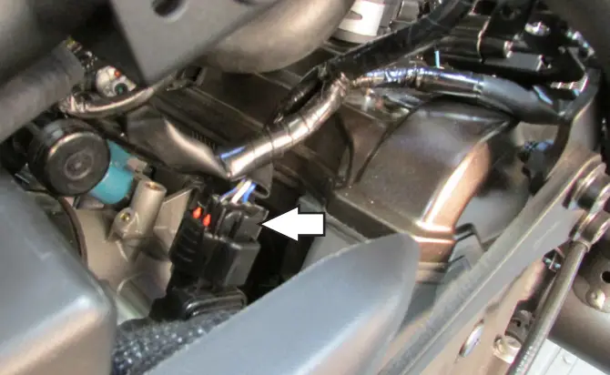
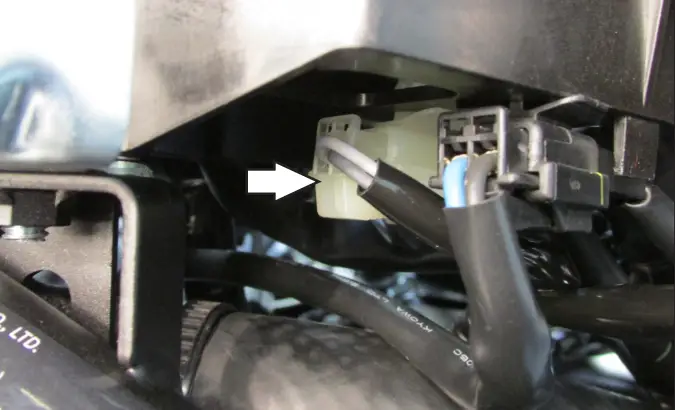 | 15. Just below the regulator/rectifier, locate and unplug the stock connectors for the bike’s Crank Position Sensor. This is a pair of CLEAR (opaque) 2-pin connectors with a WHITE and a GREY wire. |
 | 16. Plug the PC6 wiring harness in line with the stock CPS connectors. 17. Reinstall bodywork, fuel tank, and seats. 18. Affix the supplied CARB E.O. label to a conspicuous area. The best location is next to the original emissions label. Make sure to clean the surface before attaching the label. |
Download the latest map files from our website at dynojet.com/tunes.
![]() PUSH THE LIMIT
PUSH THE LIMIT
2191 MENDENHALL DRIVE, NORTH LAS VEGAS,
NV 89081 – 800-992-4993
DYNOJET.COM
© 2015-2021 DYNOJET RESEARCH ALL RIGHTS RESERVED
2015-2020 YAMAHA FZ-07/MT-07
IPC6-22065.01


