DYNOJET PC6-14009 Power Commander 6
PARTS LIST
- 1 POWER COMMANDER 6
- 1 INSTALLATION GUIDE
- 1 USB CABLE
- 2 DYNOJET DECALS
- 2 POWER COMMANDER DECALS
- 2 VELCRO STRIPS
- 1 ALCOHOL SWAB
- 1 POSI-TAP
PLEASE READ ALL DIRECTIONS BEFORE STARTING INSTALLATION.
THE IGNITION MUST BE TURNED OFF BEFORE INSTALLATION.
INPUT ACCESSORY GUIDE
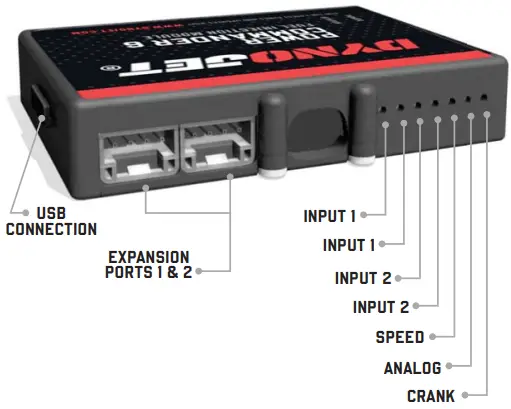
OPTIONAL ACCESSORY INPUTS
- Map: (Input 1 or 2) The PC6 has the ability to hold 2 different base maps. You can switch on the fl y between these two base maps when you hook up a switch to the MAP inputs. You can use any open/close type switch. The polarity of the wires is not important.
- Shifter: (Input 1 or 2) Used for clutch-less full throttle upshifts. Insert the wires from the Dynojet quick shifter into either Input 1 or Input 2. The polarity of the wires is not important. Set to Input 2 by default.
- Speed: If your application has a speed sensor then you can tap into the signal side of the sensor and run a wire into this input. This will allow you to calculate gear position in the Control Center Software. Once gear position is setup you can alter your map based on gear position and setup gear dependent kill times when using a quick shifter.
- Analog: This input is for a 0-5v signal such as engine temp, boost, etc. Once this input is established you can alter your fuel curve based on this input in the Power Core software.
- Launch: You can connect a wire to either Input 1 or Input 2 and then the other end to a switch. This switch when engaged (continuity) will only allow the RPM to be raised to a certain limit (set in the software). When released, you will have full RPM.
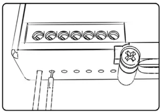
WIRE CONNECTIONS
To input wires into the PC6 fi rst remove the rubber plug on the backside of the unit and loosen the screw for the corresponding input. Using a 22-24 gauge wire, strip about 10mm from its end. Push the wire into the hole of the PC6 until it stops and then tighten the screw. Make sure to reinstall the rubber plug.
NOTE: If you tin the wires with solder it will make inserting them easier.
INSTALLING THE POWER COMMANDER 6
- Remove the seat and fuel tank.
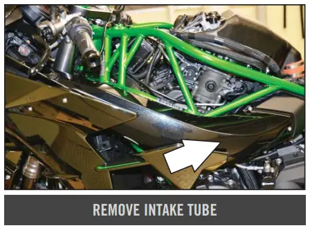
- Remove the intake tube.
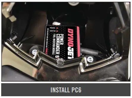
- Place the PC6 in the tail section and route the harness down the left side of the frame going towards the left side of the airbox.

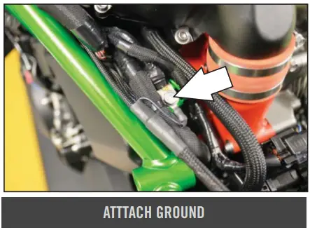
- Attach the ground wire of the PC6 to the common chassis ground on the left side of the frame.

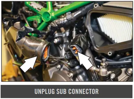
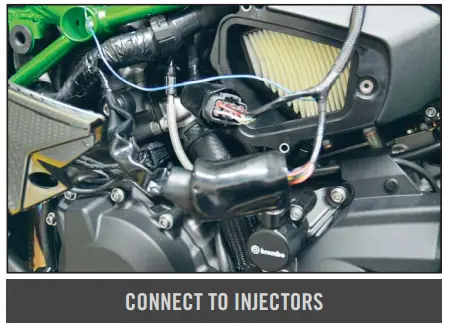
- Locate the GREY, 8 pin connector for the throttle bodies and unplug it.
This connector is located inside a rubber boot on the left side of the engine in front of the airbox.
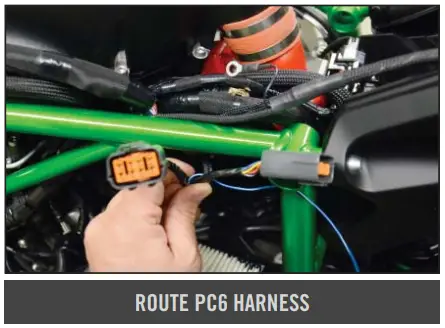
- Route the PC6 harness in-side of the frame.

- Plug the PC6 in-line of the stock wiring harness.

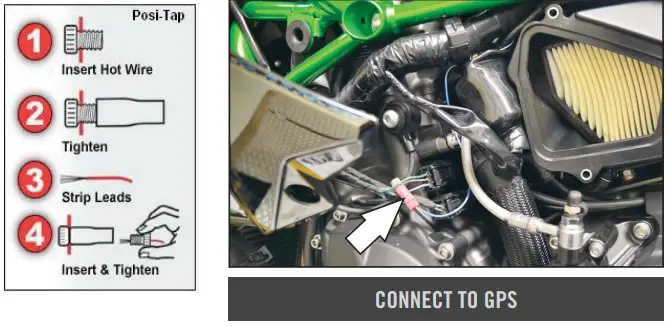
- Using the supplied Positap attach the BLUE/ WHITE wire of the PC6 to the stock GREEN/RED wire of the bike’s Gear Position Sensor.
The GPS is located above the left side engine cover.
This is a BLACK 3 pin connector.
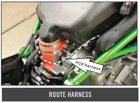
- Route the rest of the PC6 harness behind the charge pipe and go up the right side of the frame.

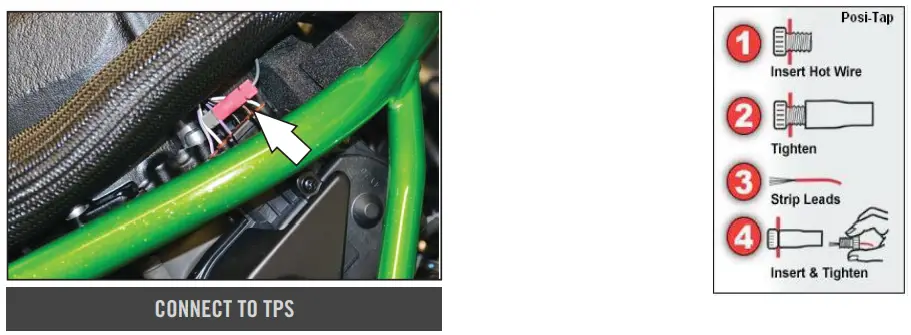
- Using the supplied Positap attach the GREY wire of the PC6 to the stock PURPLE wire of the bike’s Throttle Position Sensor.

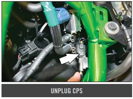
- Unplug the Crank Position Sensor connector.
This is a BLACK, 2 pin connector near the #4 coil stick.
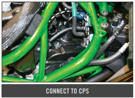
- Plug the PC6 in-line of the stock CPS and wiring harness.

- Secure the PC6 in the tail section.
- Reinstall all bodywork

ABOUT COMPANY
- 2191 MENDENHALL DRIVE, NORTH LAS VEGAS, NV 89081
- 800-992-4993
- DYNOJET.COM
- © 2010-2022 DYNOJET RESEARCH ALL RIGHTS RESERVED


