![]() PC6-16064 Power Commander 6
PC6-16064 Power Commander 6
Installation Guide 
POWER COMMANDER 6
Install guide for: PC6-16064
Model coverage: 2016-2017 Honda CRF1000L
PARTS LIST
1 POWER COMMANDER 6
1 INSTALLATION GUIDE
1 USB CABLE
2 DYNOJET DECALS
2 POWER COMMANDER DECALS
2 VELCRO STRIPS
1 ALCOHOL SWAB
2 POSI-TAPS
PLEASE READ ALL DIRECTIONS BEFORE STARTING INSTALLATION. THE IGNITION MUST BE TURNED OFF BEFORE INSTALLATION.
IPC6-16064.01
INPUT ACCESSORY GUIDE

OPTIONAL ACCESSORY INPUTS
Map
(Input 1 or 2) The PC6 has the ability to hold 2 different base maps. You can switch on the fly between these two base maps when you hook up a switch to the MAP inputs. You can use any open/close type switch. The polarity of the wires is not important.
Shifter
(Input 1 or 2) Used for clutch-less full-throttle upshifts. Insert the wires from the Dynojet quick shifter into either
Input 1 or Input 2. The polarity of the wires is not important. Set to Input 2 by default.
Speed
If your application has a speed sensor then you can tap into the signal side of the sensor and run a wire into this input. This will allow you to calculate gear position in the Control Center Software. Once gear position is set up you can alter your map based on gear position and setup gear-dependent kill times when using a quick-shifter.
Analog
This input is for a 0-5v signal such as engine temp, boost, etc. Once this input is established you can alter your fuel curve based on this input in the Power Core software.
Launch
You can connect a wire to either Input 1 or Input 2 and then the other end to a switch. This switch when engaged (continuity) will only allow the RPM to be raised to a certain limit (set in the software). When released, you will have full RPM.
WIRE CONNECTIONS
To input wires into the PC6 first remove the rubber plug on the backside of the unit and loosen the screw for the corresponding input. Using a 22-24 gauge wire, strip about 10mm from its end. Push the wire into the hole of the PC6 until it stops and then tighten the screw. Make sure to reinstall the rubber plug.
NOTE: If you tin the wires with solder it will make inserting them easier.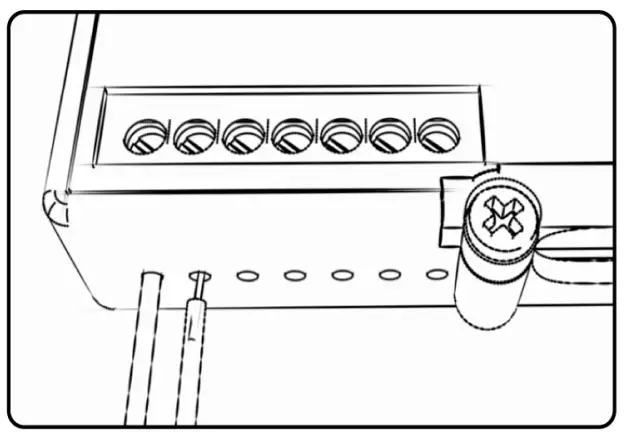 INSTALLATION GUIDE
INSTALLING THE POWER COMMANDER 6
- Remove the seat and fuel tank.
- Remove the air box.

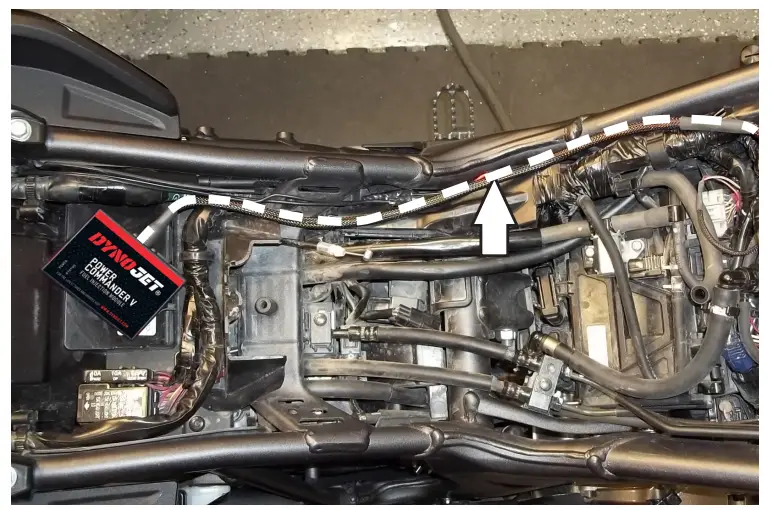
- Lay the PC6 in the tail section.
- Route the PC6 harness along the left side of the motorcycle.

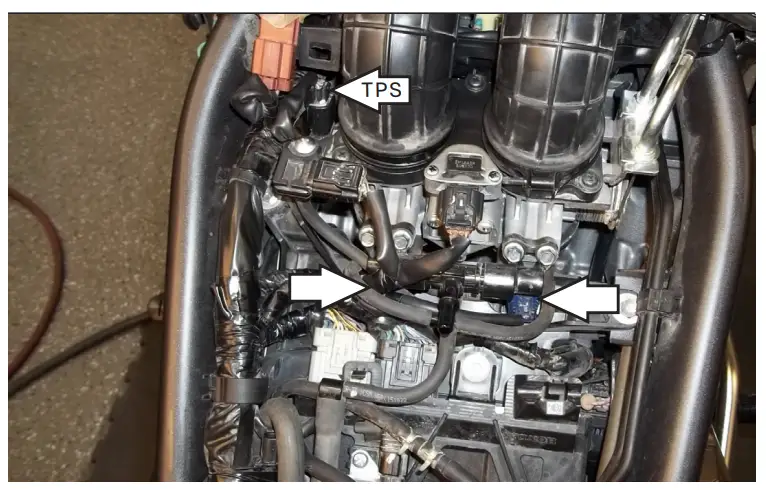
- Locate the fuel injectors and unplug the stock wiring harness from each injector.
- Unplug the stock wiring harness from the Throttle Position Sensor.
This connector is located on the left side of the throttle bodies.
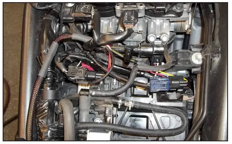
- Plug the PC6 harness in-line with the stock injectors and wiring harness.
PC6 – ORANGE wires go to the left cylinder (#1).
PC6 – YELLOW wires go to the right cylinder (#2).
- Plug the PC6 harness in-line with the stock TPS and wiring harness.

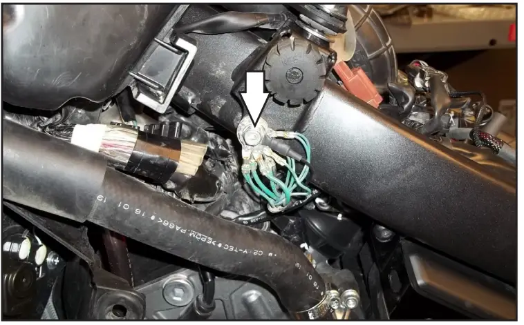
- Attach the ground wire of the PC6 to the common ground location on the left side of the frame.

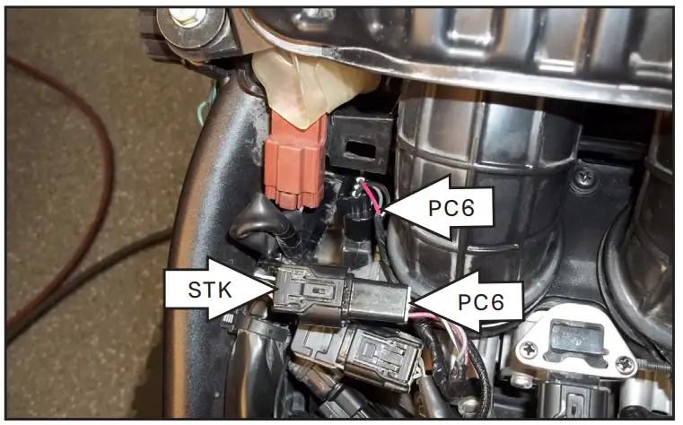
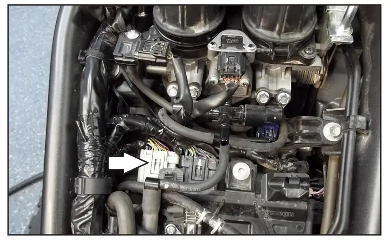
- Unplug the GREY connector from the stock ECU. The ECU is located just rear of the throttle bodies. This allows access to the wires.

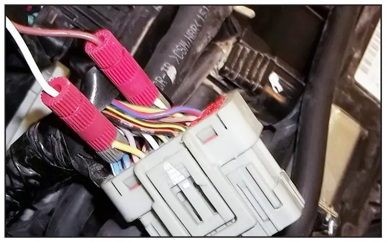
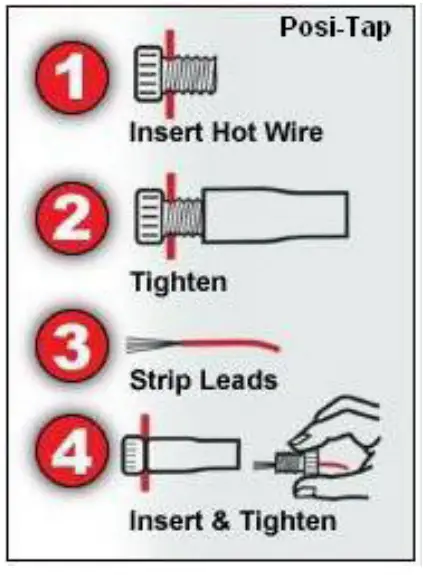
- Using the supplied Positaps connect the crank wires from the PC6 to the stock wiring harness.

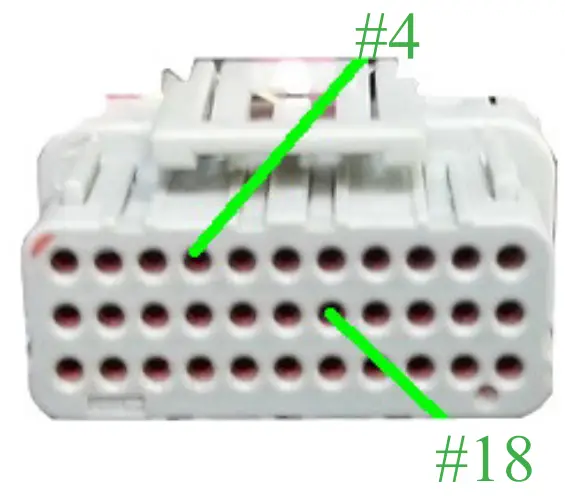
PC6 WHITE/BROWN to YELLOW (#4). PC6 BROWN/WHITE to WHITE/YELLOW (#18). #4 #18 - Secure the PC6 in the tail section using the supplied Velcro.


- Reinstall air box, fuel tank and seat
- Affix the supplied CARB E.O. label to a conspicuous area. The best location is next to the original emissions label. Make sure to clean the surface before attaching the label. Download the latest map files from our website at dynojet.com/tunes.

2191 MENDENHALL DRIVE, NORTH LAS VEGAS, NV 89081 – 800-992-4993 – DYNOJET.COM © 2016-2021 DYNOJET RESEARCH ALL RIGHTS RESERVED
![]()


