![]() PC6-14044 Power Commander 6
PC6-14044 Power Commander 6
Installation Guide
PC6-14044 Power Commander 6
POWER COMMANDER 6
Installation Guide for: PC6-14044
Model Coverage: 2019-2020 Ducati Scrambler 1100
PARTS LIST
1 POWER COMMANDER 6
1 INSTALLATION GUIDE
1 USB CABLE
2 DYNOJET DECALS
2 POWER COMMANDER DECALS
2 VELCRO STRIPS
1 ALCOHOL SWAB
PLEASE READ ALL DIRECTIONS BEFORE STARTING INSTALLATION. THE IGNITION MUST BE TURNED OFF BEFORE INSTALLATION.
INPUT ACCESSORY GUIDE
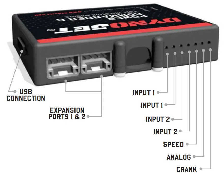
OPTIONAL ACCESSORY INPUTS
Map
(Input 1 or 2) The PC6 has the ability to hold 2 different base maps. You can switch on the fl y between these two base maps when you hook up a switch to the MAP inputs. You can use any open/close type switch. The polarity of the wires is not important.
Shifter
(Input 1 or 2) Used for clutch-less full throttle upshifts. Insert the wires from the Dynojet quick shifter into either Input 1 or Input 2. The polarity of the wires is not important. Set to Input 2 by default.
Speed
If your application has a speed sensor then you can tap into the signal side of the sensor and run a wire into this input. This will allow you to calculate gear position in the Control Center Software. Once gear position is setup you can alter your map based on gear position and setup gear dependent kill times when using a quick shifter.
Analog
This input is for a 0-5v signal such as engine temp, boost, etc. Once this input is established you can alter your fuel curve based on this input in the Power Core software.
Launch You can connect a wire to either Input 1 or Input 2 and then the other end to a switch. This switch when engaged (continuity) will only allow the RPM to be raised to a certain limit (set in the software). When released, you will have full RPM.
WIRE CONNECTIONS
To input wires into the PC6 fi rst remove the rubber plug on the backside of the unit and loosen the screw for the corresponding input. Using a 22-24 gauge wire, strip about 10mm from its end. Push the wire into the hole of the PC6 until it stops and then tighten the screw. Make sure to reinstall the rubber plug.
NOTE: If you tin the wires with solder it will make inserting them easier.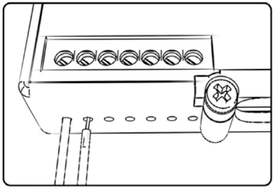 2 2019-2020 DUCATI SCRAMBLER 1100
INSTALLATION GUIDE
INSTALLING THE POWER COMMANDER 6
Remove the seat the fuel tank.
2 Route the PC6 wiring harness forward along the inside of right frame rail.
3 Attach the ground wire of the PC6 to the negative (-) side of the battery.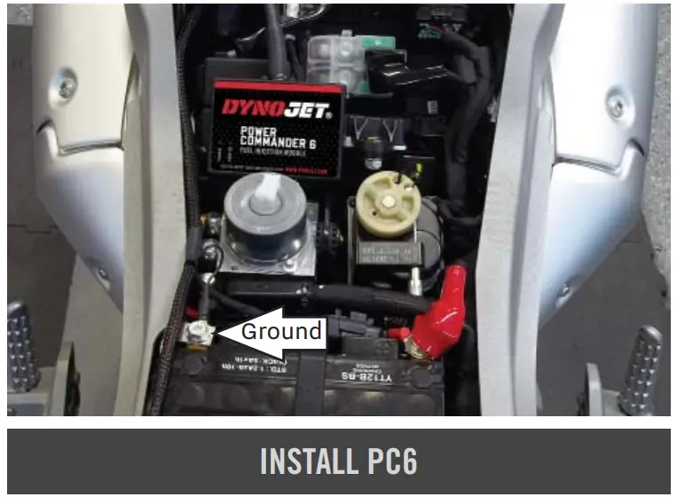 4 Unplug the Crank Position Sensor connector. This is a 3-pin, BLACK connector that sits on top of the vertical cylinder.
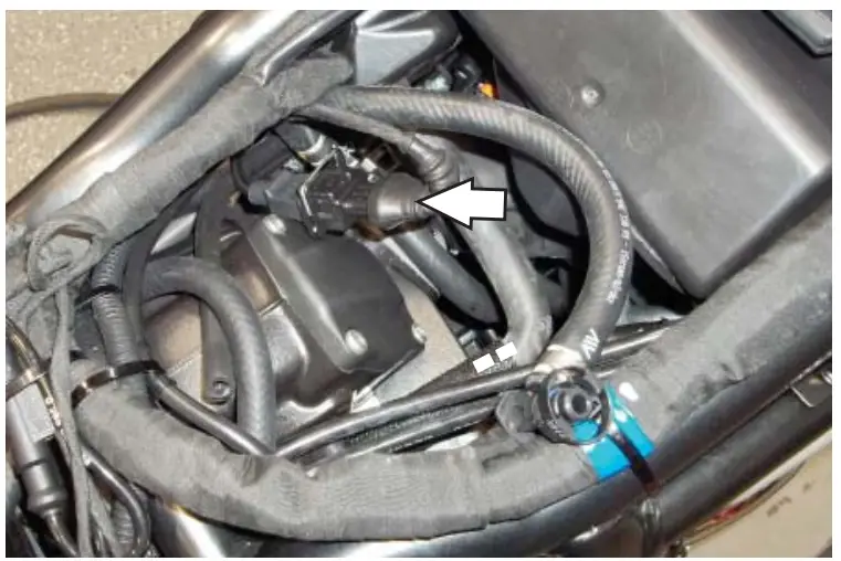 5 Plug the PC6 in-line of the stock CPS and wiring harness.
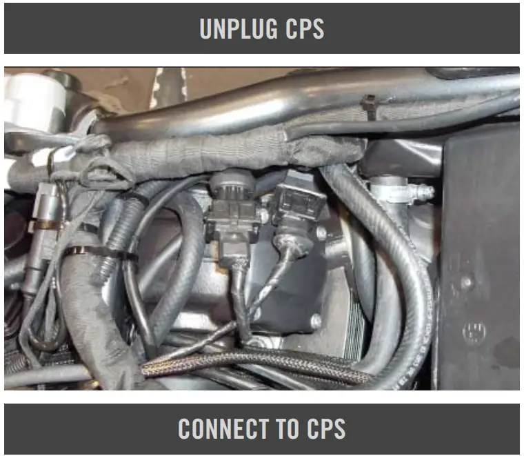 6 Remove the cosmetic cover on the left side of the engine and slide the purge valve forward to move out of the way.
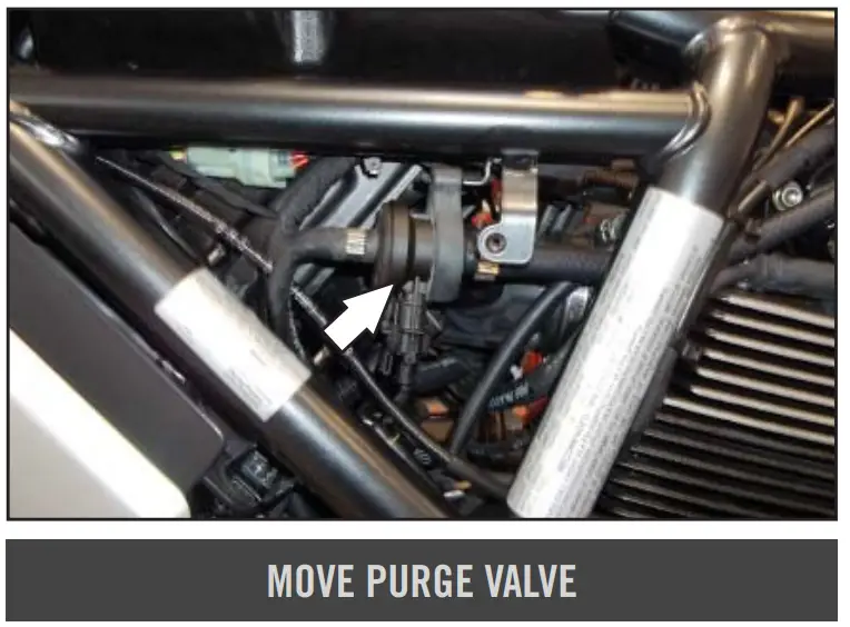 7 Unplug the stock wiring harness from the injector.
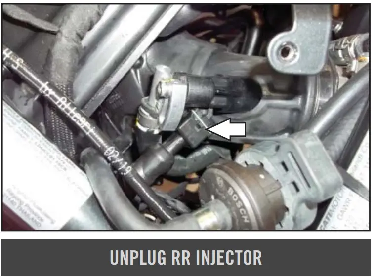 8 Connect the YELLOW colored wires of the PC6 in-line of the rear injector and wiring harness.
9 Put the purge valve back in place and reinstall the cosmetic cover.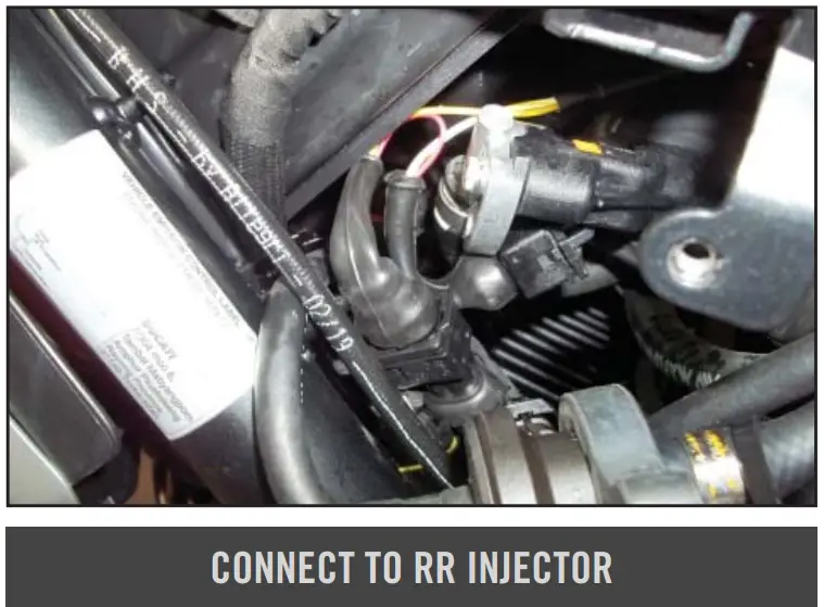 10 Remove the cosmetic cover on the right hand side of the engine.
11 Unbolt the IAC valve to gain access to the injector.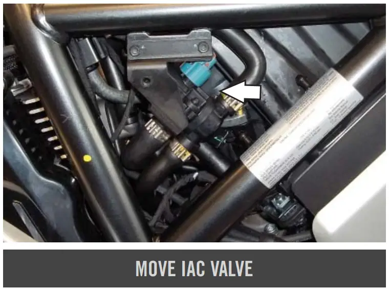 12 Unplug the stock wiring harness from the front injector.
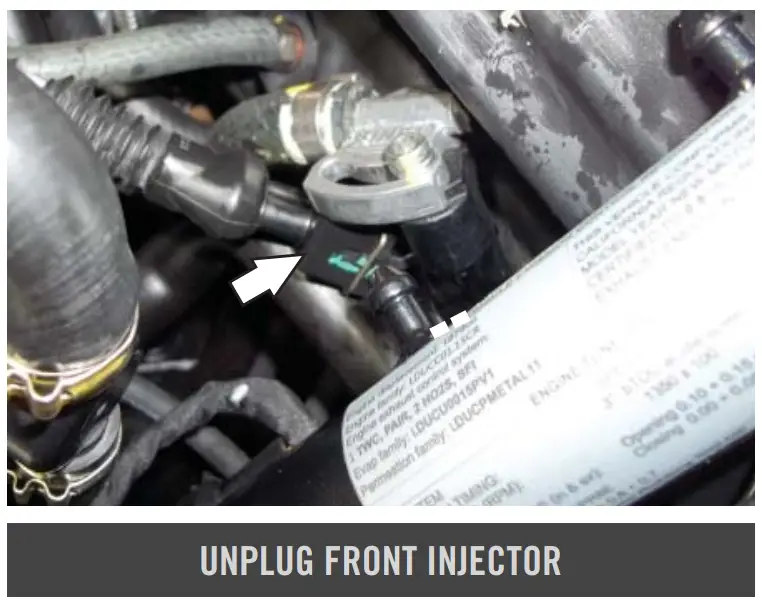 13 Plug the ORANGE colored wires of the PC6 in-line of the stock injector and wiring harness.
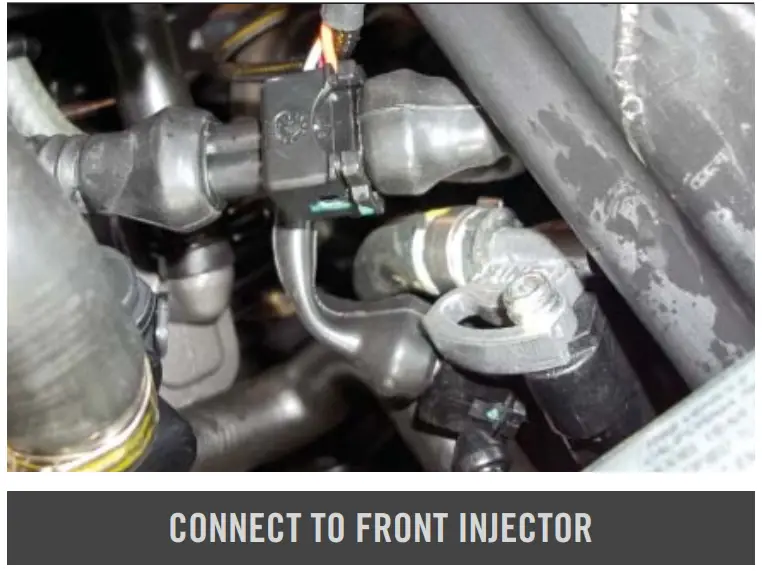 14 Unplug the TPS connector.
This is a 6-pin, BLACK connector on the right hand side of the bike just above the IAC valve.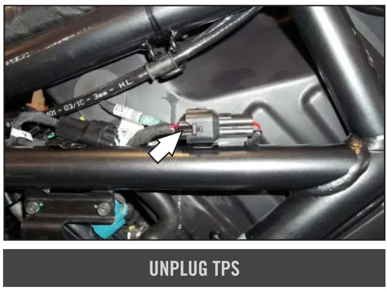 15 Plug the PC6 in-line of the TPS connector.
16 Reinstall the IAC valve and cosmetic cover.
17 Reinstall the fuel tank and the seat.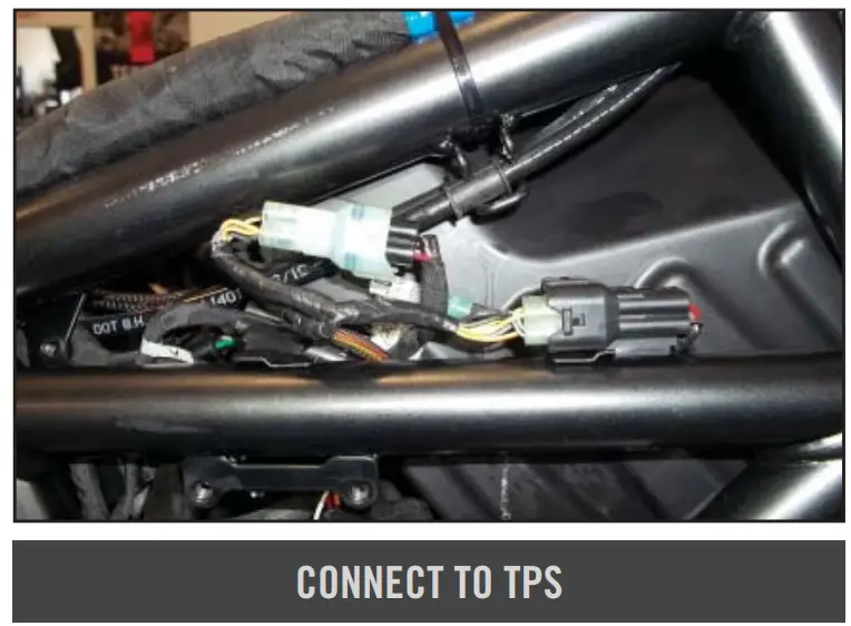 Download the latest map fi les from our web site at dynojet.com/tunes.
 ![]()
![]() 2191 MENDENHALL DRIVE
2191 MENDENHALL DRIVE
NORTH LAS VEGAS, NV
89081 – 800-992-4993 – DYNOJET.COM
© 2019-2022 DYNOJET RESEARCH ALL RIGHTS RESERVED


