DIGITAL YACHT NS5 5 Port Network Switch Instruction Manual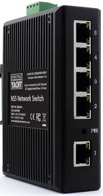
Introduction
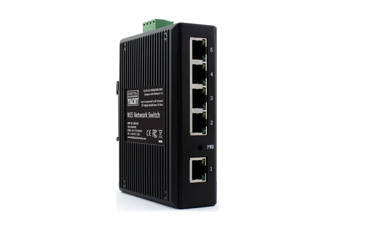
Congratulations on the purchase of your NS5 Network Switch. It is recommended that this unit is installed by a professional installer.
![]() This User Manual will provide basic information on the NS5 to allow you to install and get the NS5 working. We recommend reading and familiarising yourself with the manuals of the equipment you wish to connect to NS5.
This User Manual will provide basic information on the NS5 to allow you to install and get the NS5 working. We recommend reading and familiarising yourself with the manuals of the equipment you wish to connect to NS5.
Before you start
You will need the following items and tools to complete the installation:
- NS5 Network Switch
- Network cable
- A spare wired LAN network connection on the vessel’s Router
- Access to 12V or 24v DC power supply where the unit is to be installed
- Two or more M4 screws or other fixings appropriate to the mounting location.
To test the unit you will need:
- A device that can be connected via a network cable to the NS5 to check it is working.
Installation
Before starting installation select a suitable location for the NS5. The unit should be installed below deck in a dry location. When locating the unit, you should consider:
- Routing of power cables to the unit.
- Provision of sufficient space around the unit for cable connections.
- Maintaining the compass safe distance of 0.5m.
- Routing of network cable to the unit.
Installation Step 1 – Cabling
- NS5 is designed to be connected directly to the vessel’s 12v or 24v DC system. You will need to route a suitable power cable to the location where the NS5 will be installed. The supply to the NS5 should be fused with a 1A fuse/circuit breaker in the positive supply lead.
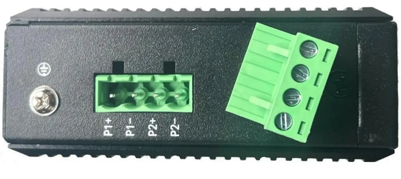
- The NS5 features a dual redundancy power supply and can have two separate power connections. Should one connection fail, it will automatically take power from the second power connection. It is not mandatory to install two power supply feeds to the NS5 and it will happily work with a single power connection to either the P1 or P2 terminals.

- The case of the NS5 can be grounded by connecting the ground screw connection shown in the previous image to a suitable point in the vessel’s ground circuit.
- The NS5 is fitted with five standard RJ45 network sockets. To connect the NS5 to the vessel’s existing network, you should route a standard Cat5 (or better) network cable from the vessel’s network router (LAN connection) through to the location where the NS5 is installed. This cable can be plugged in to any one of the NS5’s five network sockets.
- If you wish to install more than one NS5, you will need to “daisy chain” them together using a standard network patch cable. You can join any one of the five sockets on one NS5 to any one of the five sockets on the second NS5.
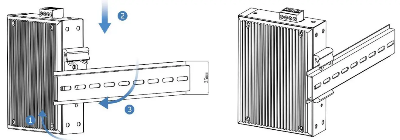
Installation Step 2 – Mechanical Fixings
Dimensioned Drawing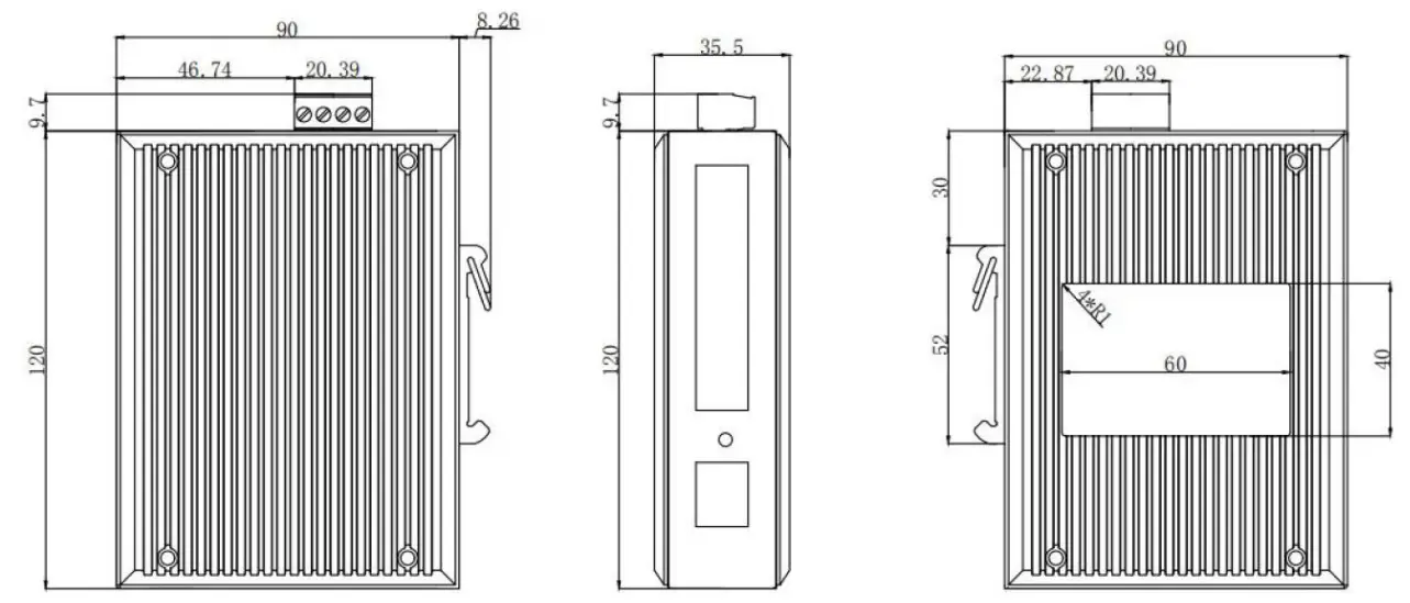
- The NS5 is designed to be mounted on a DIN rail system. If your vessel does not have a suitable DIN rail system, use the supplied 100mm length of DIN rail. Secure the DIN rail to a flat surface in the selected location. Use two M4 wood screws or other fixings suited to the material the unit is being fixed to. The unit may be installed in any orientation.

Installation Step 3 – Power
- The NS5 has a removable 4 way screw terminal, where the 12v or 24v DC power connection should be made. The NS5 has a wide input voltage range from 9v to 36v, but should not be used on a 32V DC system.
- NS5 only consumes between 40mA and 70mA (network activity dependent) of current at 12v. We recommend using suitably rated power cable to connect to the nearest source of primary 12V or 24V DC power. Ensure that the supply is connected via a 1A fuse or suitable circuit breaker. Add the fuse in the positive power connection to the unit if necessary.
- If you wish to use the dual redundancy power supply feature of the NS5, you will need to provide two separate power feeds one connected to P1+ and P1- and the other connected to P2+ and P2-. Should one feed lose power, the NS5 will automatically switch to the second feed. The NS5 will work quite happily with a single DC power feed connected to P1 or P2 and for most installations this is the normal method of powering the NS5.

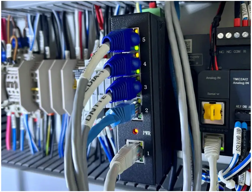
Operation
The NS5 has no configuration settings that need to be setup before using it.
Apply power to the NS5 and check that the Red Power LED comes ON. Turn on all network devices that are plugged in to the NS5 and ensure that the Yellow and Green LEDs for each active port are flashing.
Specification
| NS5 Network Switch | ||
| Provider Mode Ports | ||
| Fixed port | 5*10/100 Base – T | |
| Management Port | Not support | |
| Power interface | Terminal type, double power supply | |
| LED Indicators | PWR, Link | |
| Cable type & Transmission distance | ||
| Twisted-pair | I 0-100m ( CAT5e,CAT6 ) | |
| Network Topology | ||
| Ring topology | Not support | |
| Star topology | Support | |
| Bus topology | Support | |
| Tree Topology | Support | |
| Electrical Specifications | ||
| Input voltage | I DC: 9-36V | |
| Layer 2 Switching | ||
| MAC address table | 1K | |
| VLAN | Support VLAN,qty as 16 | |
| Forwarding packet length | 1552/1536 bytes | |
| MDX/MIDX | Support | |
| Flow control | Support | |
| Environment | ||
| Operating temperature | -40°C—+85°C | |
| Storage temperature | -40°C–+85°C | |
| Relative humidity | 5W–95% non-condensing | |
| Thermal methods | No air fan design, natural heat dissipation | |
| Mechanical Dimensions | ||
| Product size | 120X90X35.Smm | |
| Installation Method | Rail mounting | |
| Weight | _ 0.52KG | |
| EMC&INGRESS PROTECTION | ||
| IP Level | IP40 | |
| Surge protection of Power | IEC 61000-4-5 Level 3 ( 4KV/2KV ) | |
| Surge protection of Ethernet port | IEC 61000-4-5 Level 3 ( 4KV/2KV ) | |
| EMI | CLASS A | |
| ESD | IEC 61000-4-2 Level 4 ( 8K/15K ) | |
| Accessories | ||
| Accessories | I Device, terminal ( No power supply) | |
Costumer Support
User Manual for NS5 Network Switch V1.00
TEL + 44 1179 554474
www.digitalyacht.co.uk
[email protected]