![]()
USER MANUAL
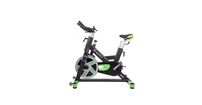
IN 9360 Indoor Bike inSPORTline Airin
NOTE: Before installation and operation, please read this operation manual carefully and save this manual for future reference.
SAFETY INSTRUCTIONS
- Read all the instructions in this manual and do warm up exercises before using this equipment.
- Before using this equipment, please consult your physician for a complete physical examination. If you feel any discomfort while exercising, please stop immediately and consult your doctor.
- Before exercising and to avoid injuring your muscles, perform warm-up exercise for each muscle group is highly recommended. Please refer to Warm Up Routine section of the Owner’s Manual.
- Keep the equipment indoors, away from moisture and dust. Place the equipment on a level surface, with a mat beneath it to protect the floor or carpet. Make sure that there is enough clearance around the equipment to mount, dismount, and use it.
- Inspect and properly tighten all parts regularly. Replace any worn parts immediately.
- Ensure that your fingers or clothing do not catch in the equipment moving parts.
- Please keep children and pets away from the equipment at all times. It is only suitable for adults.
- The equipment should not be used by persons weighting more than 150 kg. Serious injury may occur if the user’s weight exceeds the limit shown here.
- If you hear unusual noise when exercising, please stop your training immediately. Do not use the equipment until the problem has been resolved.
- To prevent injuring you when stop exercising, do not touch the flywheel immediately.
- None of the adjustment means should not be left to protrude so could interfere with the movement of the user
- Freestanding unit must be installed on a stable and level surface. Keep a clearance of min. 0.6 m around this device for higher safety.
- Excessive or improper exercise can cause injury.
- Class – HC (according to EN ISO 20957), intended for home use
PARTS LIST
| No | Description | QTY |
| 1 | Main Frame | 1 |
| 2 | Front stabilizer bar 40x80x2T | 1 |
| 3 | Rear stabilizer bar 40x80x2T | 1 |
| 4 | Upright post 40x80x2T | 1 |
| 5 | Seat post 40x80x2T | 1 |
| 6 | Handlebar Φ32x2T | 1 |
| 7 | Sear moving bracket | 1 |
| 8 | Plastic fastener 50x100x100mml | 2 |
| 9 | Seat VL-6100 | 1 |
| 10 | Flywheel Φ468 | 1 |
| 11 | Belt wheel Φ260 with Axis | 1 |
| 12 | Belt 1590 PK5 | 1 |
| 13R | Main chain cover-R | 1 |
| 13L | Main chain cover-L | 1 |
| 15R | Inner chain cover-R | 1 |
| 15L | Inner chain cover-L | 1 |
| 17 | Side trim cover | 1 |
| 18R | 3PCS Crank-R | 1 |
| 18L | 3PCS Crank-L | 1 |
| 19 | Plastic cap for Crank | 2 |
| 20R | Pedal JD-304V-R | 1 |
| 20L | Pedal JD-304V-L | 1 |
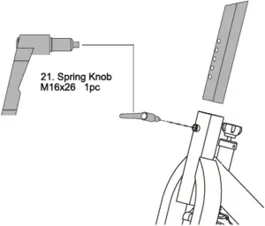
| 21 | Spring knob M16x26 | 2 |
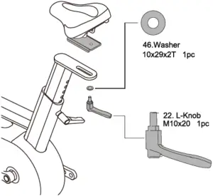
| 22 | L-knob M10x20 | 1 |
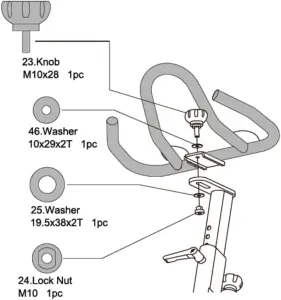
| 23 | Knob M10x28 | 1 |
| 24 | Lock Nut M10 | 1 |
| 25 | Washer 19.5x38x2T | 1 |
| 26R | Magnet plastic cover-R | 1 |
| 26L | Magnet plastic cover-L | 1 |
| 27 | Support bar 20x20x1.4T | 1 |
| 28 | Magnet bracket | 1 |
| 29 | Tension control bar | 1 |
| 30 | Fixed cover | 1 |
| 31 | П shape fastener | 2 |
| 32 | Spring washer | 1 |
| 33 | Nylon nut M6 | 2 |
| 34 | Nylon nut M8 | 2 |
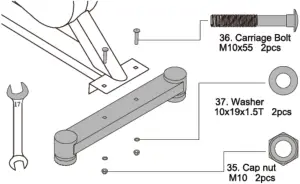
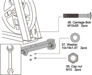
| 35 | Cap nut M10 | 4 |
| 36 | Carriage bolt M10x55 | 4 |
| 37 | Washer 10x19x1.5T | 6 |
| 38 | Hex. Nut M10x6T | 4 |
| 39 | Hex socket head bolt M8x38 | 2 |
| 40 | Spring Φ2.6×18 | 1 |
| 41 | Adjustment bar Φ6×60 | 1 |
| 42 | Compressed spring Φ1.5×9 | 1 |
| 43 | Crank plug | 2 |
| 44 | Flange Nut M12x1.5×10.4T | 4 |
| 45 | Hex socket head bolt M8x12 | 3 |
| 46 | Washer 10x29x2T | 2 |
| 47 | Self-tapping screw M5x12 | 5 |
| 48 | Bottle holder | 1 |
| 49 | Screw M5x10 | 2 |
| 50 | Philips screw M3x10 | 2 |
| 51 | Steel sleeve Φ12*17*9 | 1 |
| 52 | Self-tapping screw M4.5×15 | 2 |
| 53 | Self-tapping screw M4.2×10 | 13 |
| 54 | Hex. bolt M6x35 | 1 |
| 55 | Idle wheel fixture | 1 |
| 56 | Nylon nut M10x9T | 2 |
| 57 | Steel sleeve Φ25.1x32x10T | 1 |
| 58 | Steel bearing 6005 -2RS | 2 |
| 59 | C -ring Φ20 | 2 |
| 60 | C -ring Φ25 | 1 |
| 61 | Idle wheel | 1 |
| 62 | Wave washer 27x34x0.3T | 1 |
| 63 | Plastic washer 10x20x2T | 2 |
| 64 | Wire plug Φ17 | 1 |
| 65 | Steel sleeve Φ10.3x15x8T | 1 |
| 66 | Axis Φ20x155mm | 1 |
| 67 | Wave washer 21x27x0.3T | 1 |
| 68 | Washer 20.5x25x0.5T | 1 |
| 69 | Hex. bolt M10x32 | 1 |
| 70 | Nylon nut M10x6T | 2 |
| 71 | Plastic bearing Φ12.8×21.4×6.7T | 4 |
| 72 | Plastic sleeve Φ7.9×12.7×23.5mm | 2 |
| 73 | Fixed plate | 2 |
| 74 | Cushion knob M10x25 | 4 |
| 75 | Cap Φ76 | 4 |
| 76 | Transport wheel Φ70 | 2 |
| 77 | Tension control knob M10 | 1 |
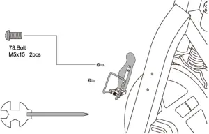
| 78 | Bolt M5x15 | 2 |
| 79 | Bolt M5x10 | 2 |
| 80 | Self-tapping screw M4.5×25 | 5 |
| 81 | Plastic cap | 1 |
| 82 | Washer 12x24x1.5T | 2 |
| 83 | Washer Φ5 | 2 |
| 84 | Plastic cover | 1 |
| 85 | Washer 10x16x1.5T | 1 |
| 86 | Plastic spacer 34.8*34.8*6T | 1 |
| 87 | Oval cover | 1 |
| 88 | C ring Φ17 | 1 |
HARDWARE AND TOOLS LIST
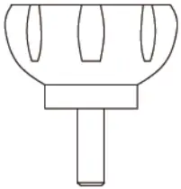
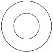
NO.23 Knob M10x28 1PC NO.25 Washer 19.5x38x2T 1PC

NO.46 Washer 10x29x2T 2PCS NO.35 Cap nut M10 4PCS


NO.24 Lock Nut M10 1PC NO.37 Washer 10x19x1.5T 4PCS
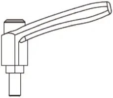
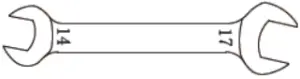
NO.22 L-knob M10 1PC Open end wrench 14,17mm 1PC
N 0.36 Carriage bolt M10x55 4PCS Screwdriver 1 PC
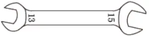
Open end wrench 13,15mm 1PC
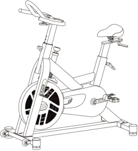
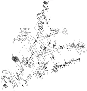
OVERVIEW DRAWING
ASSEMBLY
STEP 1
STEP 2
STEP 3
STEP 4
STEP 5
STEP 6
STEP 7
STEP 8

HOW TO USE
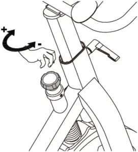
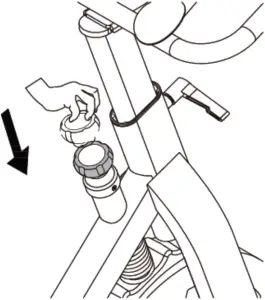
Tension Adjustment
Turn knob clockwise to increase tension. Turn knob counter-clockwise to decrease tension.
Emergency Stop
Press down the knob to stop the flywheel.

SPD PEDALS USAGE
GENERAL SAFETY INFORMATION
WARNING! To avoid serious injuries:
- SPD pedals are designed so that you release them only you intend to release. They are not designed to release automatically at times such as when falling off the bike. This is a safety measure to prevent you from losing balance and falling off the bike as a result of your feet becoming accidentally released from the pedals.
- Use only SPD shoes with this product. Other types of shoes may not release from the pedals, or may release unexpectedly.
- Before attempting to ride with these pedals and shoes, make sure you understand the operation of engagement / release mechanism for the pedals and cleats (shoes).
- Before you attempt to ride with these pedals and shoes, please practice engaging and releasing each shoe from its pedal until you can do so naturally and with minimal effort.
- Before riding, adjust the spring tension of the pedals to your liking.
- Remember to check the cleats periodically for wear. When the cleats are worn, replace them.
Always check the spring tension after replacing the pedal cleats and before riding. If you do not maintain both your shoes and cleats in good condition, release and engagement to be the pedals could become unpredictable of difficult, which could result in severe injury. - Obtain and read the service instructions carefully prior to installing the parts. Loose worn, or damaged parts may cause serious injury to the rider.
- If you have any questions concerning your pedals, contact a professional dealer.
- Read these Technical Service Instructions carefully, and keep them in a safe for later reference.
BE SURE TO READ AND FOLLOW ABOVE WARNING CAREFULLY
If the warnings are not following, your shoes may not come out of the pedals when you intend or they may come out unexpectedly or accidentally, and severe injury may result.
NOTE: Check that there is no looseness in any joints or connections before riding the bike. In addition, if pedaling performance does not feel normal, check this once more.
WARNING! The cleats are designed to engage and release from the pedals when the cleats and pedals are facing forward.
BINDING INSTRUCTIONS
FAILURE TO FOLLOW THESE INSTRUCTIONS MAY RESULT IN SERIOUS PERSONAL INJURY
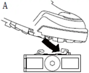
A. ENGAGING THE CLEATS WITH THE PEDALS
Press the cleats into the pedals with a forward and downward motion.
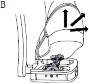
B. RELEASING THE CLEATS FROM THE PEDALS
The cleats can be released by twisting your heels in any direction.
Note: It is necessary to practice releasing until you are accustomed to the amount of force and the angle required to release.
Attaching the cleats:
C. With a pair of pliers or a similar tool, pull off the rubber cover to expose the cleat mounting holes.
Note: This step may not be necessary depending on the type of shoes.
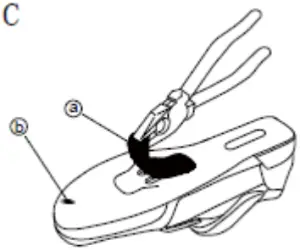
a. Rubber cover for cleat mounting holes
b. SPD shoes
D. Remove the sockliner and position a cleat nut over the oval holes.
Note: This step may not be necessary depending on the type of shoes.
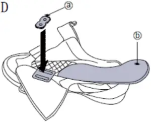
a. Cleat nut
b. Sockliner
E. From the bottom of the shoes, position a cleat and then a cleat adapter over the cleat holes. The cleats are compatible with both left and right pedals. Provisionally tighten the cleat mounting bolts. Position the triangular portion of the cleat toward the front of the shoe.
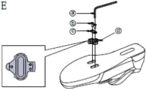
a. 4mm Allen key
b. Cleat mounting bolts
c. Cleat adapter
d. Cleat
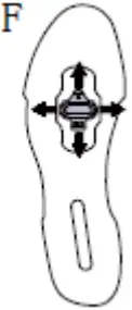
F. ADJUSTING THE CLEAT POSITION
The cleat has an adjustment range of 20 mm front to back and 5 mm right to left. After provisionally tightening the cleat, practice engaging and releasing, one shoe at a time. Readjust to determine the best cleat position.
After you have determined the best cleat position, firmly tighten the cleat mounting bolts with a 4 mm Allen key.
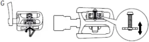
G. ADJUSTING THE SPRING TENSION OF THE BINDING
The spring force is adjusted by means of adjustment bolts. The adjustment bolts are located behind each of the bindings, and there is one adjustment bolt on each pedal. Equalize the spring tension by referring to the tension indicators and by counting the number of turns of the adjustment bolts.
If the tension indicator is at the strongest or the weakest position, do not turn the adjustment bolt any further.
Note: In order to prevent accidental release from occurring, make sure all the spring tension are properly adjusted.
The spring tensions should be adjusted equally for both right and left pedals. If they are not adjusted equally, it can cause the rider difficulty to engage or release from the pedals.
Cleat replacement:
Cleats wear out over time and should be replaced periodically. Cleats should be replaced when it becomes difficult to release, or it starts to release with much less effort than the when it was in new condition.
RIGHT BODY KEEPING
During a workout, you can either keep your body uprightly or you can lean on your forearms on handlebars. Don’t overstretch your legs while pedaling. In a full-pedal position, your leg should be slightly bent in knee. Keep your head in line with your back to reduce possible pain on neck muscles. Exercise smoothly and keep right frequency.
MAINTENANCE
Cleaning
The bike trainer can be cleaned with a soft cloth and mild detergent. Do not use abrasives or solvents on plastic parts. Please wipe your perspiration off the bike trainer after each use. Please inspect all assembly bolts and pedals on the machine for proper tightness every week.
Storage
Store the bike trainer in a clean and dry environment away from children.
Thread sealant instruction
If any parts need to be applied thread sealant, the parts must be cleaned before applying. It needs at least 12 hours to a day to wait the sealant dry, do not use the bike until the thread sealant is fully dry.
TROUBLESHOOTING
The bike trainer wobbles or shakes when in use
Turn the adjustable leveler on the front stabilizer or rear stabilizer as needed to level the bike trainer.
Squeaking noise when in use
The bolts may be loose on the bike trainer. Inspect all bolts and tighten as needed.
WARM UP ROUTINE
| QUADRICEPS STRETCH With one hand against a wall for balance, reach behind you and pull your right foot up. Bring your heel as close to your buttocks as possible. Hold for 15 counts and repeat with left foot. | 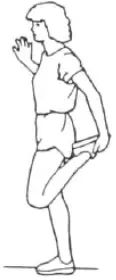 |
| INNER THIGH STRETCH Sit with the soles of your feet together and your knees pointing outward. Pull your feet as close to your groin as possible. Gently push your knees toward the floor. Hold for 15 counts. | 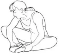 |
| TOE TOUCHES Slowly bend forward from your waist, letting your back and shoulders relax as you stretch toward your toes. Reach as far as you can and hold for 15 counts. | 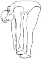 |
| HAMSTRING STRETCHES Extend your right leg. Rest the sole of your left foot against your right inner thigh. Stretch toward your toe as far as possible. Hold for 15 counts. Relax and then repeat with left leg. | 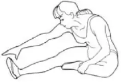 |
ENVIRONMENT PROTECTION
After the product lifespan expired or if the possible repairing is uneconomic, dispose it according to the local laws and environmentally friendly in the nearest scrapyard.
By proper disposal you will protect the environment and natural sources. Moreover, you can help protect human health. If you are not sure in correct disposing, ask local authorities to avoid law violation or sanctions.
TERMS AND CONDITIONS OF WARRANTY, WARRANTY CLAIMS
General Conditions of Warranty and Definition of Terms
All Warranty Conditions stated hereunder determine Warranty Coverage and Warranty Claim Procedure. Conditions of Warranty and Warranty Claims are governed by Act No. 40/1964 Coll. Civil Code, Act No. 513/1991 Coll., Commercial Code, and Act No. 634/1992 Coll., Consumer Protection Act, as amended, also in cases that are not specified by these Warranty rules.
The seller is SEVEN SPORT s.r.o. with its registered office in Borivojova Street 35/878, Prague 13000, Company Registration Number: 26847264, registered in the Trade Register at Regional Court in Prague, Section C, Insert No. 116888.
According to valid legal regulations it depends whether the Buyer is the End Customer or not.
“The Buyer who is the End Customer” or simply the “End Customer” is the legal entity that does not conclude and execute the Contract in order to run or promote his own trade or business activities.
“The Buyer who is not the End Customer” is a Businessman that buys Goods or uses services for the purpose of using the Goods or services for his own business activities. The Buyer conforms to the General Purchase Agreement and business conditions to the extent specified in the Commercial Code.
These Conditions of Warranty and Warranty Claims are an integral part of every Purchase Agreement made between the Seller and the Buyer. All Warranty Conditions are valid and binding, unless otherwise specified in the Purchase Agreement, in the Amendment to this Contract or in another written agreement.
Warranty Conditions
Warranty Period
The Seller provides the Buyer a 24 months Warranty for Goods Quality, unless otherwise specified in the Certificate of Warranty, Invoice, Bill of Delivery or other documents related to the Goods. The legal warranty period provided to the Consumer is not affected.
By the Warranty for Goods Quality, the Seller guarantees that the delivered Goods shall be, for a certain period of time, suitable for regular or contracted use, and that the Goods shall maintain its regular or contracted features.
The Warranty does not cover defects resulting from (if applicable):
- User’s fault, i.e. product damage caused by unqualified repair work, improper assembly, insufficient insertion of seat post into frame, insufficient tightening of pedals and cranks
- Improper maintenance
- Mechanical damages
- Regular use (e.g. wearing out of rubber and plastic parts, moving mechanisms, joints etc.)
- Unavoidable event, natural disaster
- Adjustments made by unqualified person
- Improper maintenance, improper placement, damages caused by low or high temperature, water, inappropriate pressure, shocks, intentional changes in design or construction etc.
Warranty Claim Procedure
The Buyer is obliged to check the Goods delivered by the Seller immediately after taking the responsibility for the Goods and its damages, i.e. immediately after its delivery. The Buyer must check the Goods so that he discovers all the defects that can be discovered by such check.
When making a Warranty Claim the Buyer is obliged, on request of the Seller, to prove the purchase and validity of the claim by the Invoice or Bill of Delivery that includes the product’s serial number, or eventually by the documents without the serial number. If the Buyer does not prove the validity of the Warranty Claim by these documents, the Seller has the right to reject the Warranty Claim.
If the Buyer gives notice of a defect that is not covered by the Warranty (e.g. in the case that the Warranty Conditions were not fulfilled or in the case of reporting the defect by mistake etc.), the Seller is eligible to require a compensation for all the costs arising from the repair. The cost shall be calculated according to the valid price list of services and transport costs.
If the Seller finds out (by testing) that the product is not damaged, the Warranty Claim is not accepted. The Seller reserves the right to claim a compensation for costs arising from the false Warranty Claim.
In case the Buyer makes a claim about the Goods that is legally covered by the Warranty provided by the Seller, the Seller shall fix the reported defects by means of repair or by the exchange of the damaged part or product for a new one. Based on the agreement of the Buyer, the Seller has the right to exchange the defected Goods for a fully compatible Goods of the same or better technical characteristics. The Seller is entitled to choose the form of the Warranty Claim Procedures described in this paragraph.
The Seller shall settle the Warranty Claim within 30 days after the delivery of the defective Goods, unless a longer period has been agreed upon. The day when the repaired or exchanged Goods is handed over to the Buyer is considered to be the day of the Warranty Claim settlement. When the Seller is not able to settle the Warranty Claim within the agreed period due to the specific nature of the Goods defect, he and the Buyer shall make an agreement about an alternative solution. In case such agreement is not made, the Seller is obliged to provide the Buyer with a financial compensation in the form of a refund.
![]()
SEVEN SPORT s.r.o.
Registered Office: Borivojova 35/878, 130 00 Praha 3, Czech Republic
Headquarters: Delnicka 957, 749 01 Vitkov, Czech Republic
Warranty & Service Centre: Cermenska 486, 749 01 Vitkov, Czech Republic
CRN: 26847264
VAT ID: CZ26847264
Phone: +420 556 300 970
E-mail: [email protected] [email protected] [email protected]
Web: www.insportline.cz
SK
INSPORTLINE s.r.o.
Headquarters, Warranty & Service centre: Elektricna 6471, 911 01 Trencin, Slovakia
CRN: 36311723
VAT ID: SK2020177082
Phone: +421(0)326 526 701
E-mail: [email protected] [email protected] [email protected]
Web: www.insportline.sk
Date of Sale: Stamp and Signature of Seller:


