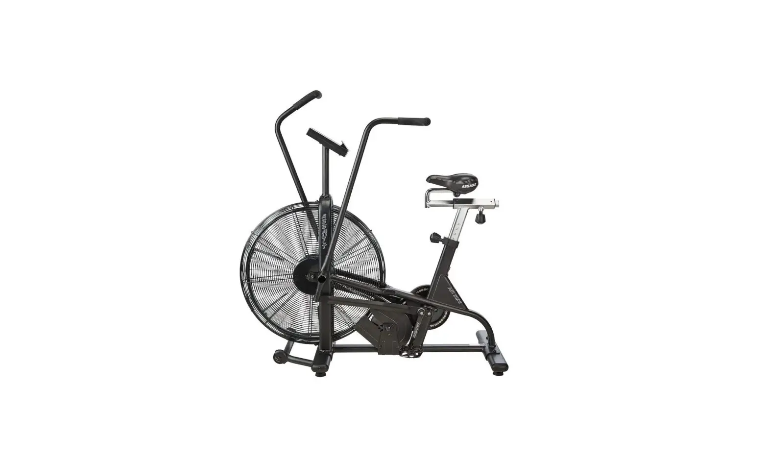
kmart 43203963 Assault Air Bike Owner’s Manual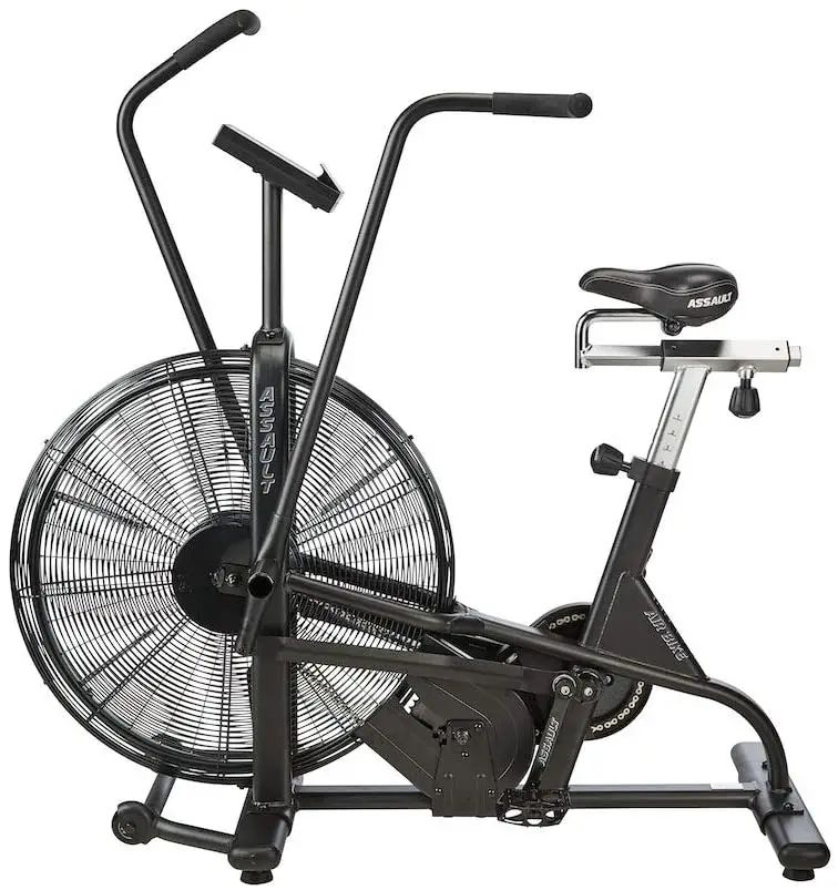
IMPORTANT:
Read all instructions carefully before using this product.
Retain this owner’s manual for future reference.
The specifications of this product may vary from this photo,subject to change without notice.
IMPORTANT SAFETY INSTRUCTIONS
Basic precautionsshould always be followed, including the following important safety instructions when using this equipment. Read all instructions before using this equipment.
- Read all instructions and follow it carefully before using this equipment. Make sure The equipment is properly assembled and tightened before use.
- Before exercise, in order to avoid injuring the muscle, warm-up exercises are recommended.
- Please make sure all parts are not damaged and fixed well before use. This equipment should be placed on a flat surface when using. Using a mat or other covering material on the ground is recommended.
- Please wear proper clothes and shoes when using this equipment; do not wear clothes that might catch any part of the equipment.
- Do not attempt any maintenance or adjustments other than those described in this manual. Should any problems arise, discontinue use and consult your local dealer.
- Be careful when step on or leave the pedal always hold the handlebars first. Make the pedal at your side at the lowest position,step on the pedal, and stride over the main frame then step on the other pedal. After exercise, please also make one pedal at the lowest position and leave your foot on the higher pedal first and then another.
- Do not use the equipment outdoors. It is not a commercial model.
- This equipment is for household use only.
- Only one person at a time should use this equipment.
- If you feel any chest pains, nausea, dizziness, or short of breath, you should stop exercising immediately and consult your physician before continuing.
- Care should be taken in mounting or dismounting the equipment.
- Do not allow children to use or play on the equipment. Keep children and pets away from the equipment while in use. This machine is designed for adults use only. The minimum free space required for safe operation is not less than two meters.
- The maximum weight capacity for this product is 120kgs.
WARNING: Before beginning any exercise program consult your physician. This is especially important for the people who are over 35 years old or who have pre existing health problems. Read all instructions before using any fitness equipment.
CAUTION: Read all instructions carefully before operating this product. Retain this Owner’s Manual for future reference
PARTS LIST
| No. | Description | Qty | No. | Description | Qty | ||
| 1 | Main Frame | 1 | 50 | Flange Nut M10×1.0 | 4 | ||
| 2 | Meter Post | 1 | 51 | Eye Bolt M6x36 | 4 | ||
| 3 | Left Handrail Arm | 1 | 52 | Hexagon Nut M10x1.0 | 4 | ||
| 4 | Right Handrail Arm | 1 | 53 | Ring Φ10 | 4 | ||
| 5 | Handrail | 2 | 54 | Bearing 6003Z | 4 | ||
| 6 | Left and Right Foot Bar | 2 | 55 | Hexagon Bolt M6x15 | 4 | ||
| 7 | Front Stabilizer | 1 | 56 | Belt Pulley | 1 | ||
| 8 | Rear Stabilizer | 1 | 57 | Gear Ф18xФ13×6 | 1 | ||
| 9 | Seat Post | 1 | 58 | Fan Wheel AxleФ10×140 | 1 | ||
| 10 | Seat Slider | 1 | 59 | Belt | 1 | ||
| 11 | Computer | 1 | 60 | Left Foot Pedal | 1 | ||
| 12 | Cross Pan Head Screw M5x10 | 2 | 61 | Right Foot Pedal | 1 | ||
| 13 | Extension Sensor Wire | 1 | 62 | Spacer | 4 | ||
| 14 | Wire Plug Ф12 | 3 | 63 | Ring Φ32 | 2 | ||
| 15 | Hexagon Bolt M8x16 | 6 | 64 | Bearing Ф32xФ13×10 | 2 | ||
| 16 | Curve Washer Ф16xФ8×1.5 | 2 | 65 | Crank Cover | 2 | ||
| 17 | Nut M8 | 2 | 66 | Flange Nut M10×1.25 | 2 | ||
| 18 | Cross Pan Head Self-drilling Tapping Screw ST4.2×20 | 1 | 67 | Left Crank | 1 | ||
| 19 | Senor Wire | 1 | 68 | Right Crank | 1 | ||
| 20 | Axle | 2 | 69 | Left Nylon Nut 1/2″ | 1 | ||
| 21 | Locking Plate | 2 | 70 | Right Nylon Nut 1/2″ | 1 | ||
| 22 | Bolt M6x10 | 10 | 71 | Ring Φ20 | 2 | ||
| 23 | Wave Washer Ф26xФ16×0.3 | 2 | 72 | Bearing 6004Z | 2 | ||
| 24 | Metal Bushing Ф28xΦ16×16 | 4 | 73 | Chain | 1 | ||
| 25 | D-shaped Washer Ф28xФ16×5 | 2 | 3 | 74 | Magnetic Wheel Axle | 1 | |
| 26 | Flat Washer Ф10xФ25×2.0 | 2 | 75 | Hexagon Nut M5 | 22 | ||
| 27 | Spring Washer Ф19.5xФ11.5×3 | 2 | 76 | Spring Washer Ф5 | 8 | ||
| 28 | Hexagon Bolt M10x20 | 2 | 77 | Hexagon Bolt M5x15 | 8 | ||
| 29 | Carriage Bolt M8 x 40 | 4 | 78 | Chain Pulley | 1 | ||
| 30 | Curve Washer Ф20xФ8×1.5 | 4 | 79 | Seat Height Adjustment Knob M16x25 | 1 | ||
| 31 | Cap Nut M8 | 4 | 80 | Plastic Bushing | 1 | ||
| 32 | Hexagon Bolt M10x50 | 2 | 81 | Adjustment Knob M16x35 | 1 | ||
| 33 | Metal Bushing Ф24×15 | 4 | 82 | Seat Post Plastic Bushing | 1 | ||
| 34 | Nylon Nut M10 | 2 | 83 | End Cap 30×30 | 1 | ||
| 35 | End Cap Ф32 | 2 | 84 | Seat Cushion | 1 | ||
| 36 | End Cap Ф28 | 2 | 85 | Left Flywheel Cover | 1 | ||
| 37 | Handrail Arm Foam Grip | 2 | 86 | Cross Pan Head Bolt M5×10 | 8 | ||
| 38 | Flat Washer Ф20xФ8×1.5 | 4 | 87 | Screw M6x10 | 7 | ||
| 39 | Hexagon Bolt M8x40 | 2 | 88 | Right Flywheel Cover | 1 | ||
| 40 | Movable Wheel | 2 | 89 | Blade | 4 | ||
| 41 | Nylon Nut M8 | 2 | 90 | Bolt M5x40 | 4 | ||
| 42 | End Cap for Front and Rear Stabilizer 80×40 | 4 | 91 | Fly Wheel | 1 | ||
| 43 | Hexagon Nut M10 | 4 | 92 | Bolt M5x35 | 2 | ||
| 44 | Cushion | 4 | 93 | Magnet | 1 | ||
| 45 | Left Chain Cover | 1 | 94 | Sensor Holder | 1 | ||
| 46 | Right Chain Cover | 1 | 95 | Fan Wheel Axle | 1 | ||
| 47 | Hexagon Nut M6 | 8 | 96 | Footrest | 2 | ||
| 48 | Spring Washer Ф6 | 8 | 97 | End Cap Ф38 | 2 | ||
| 49 | Tension Bracket | 4 | |||||
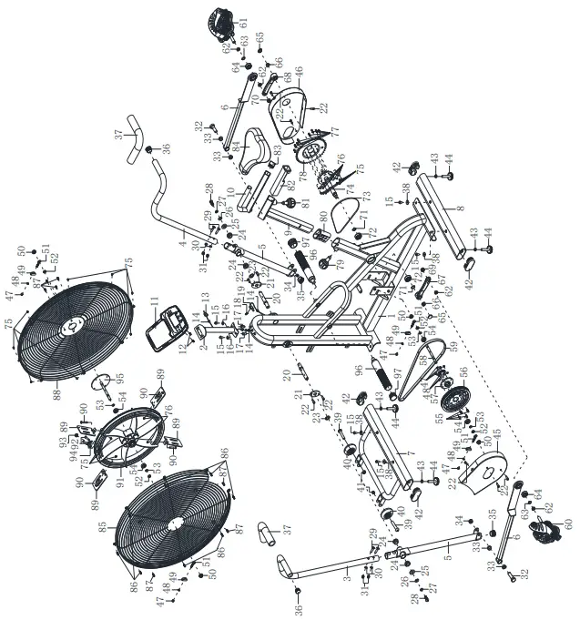
OVERVIEW DRAWING
HARDWARE & TOOLS
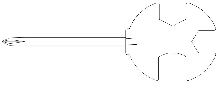
- Spanner with Phillips Screwdriver S13-S14-S15 1PC

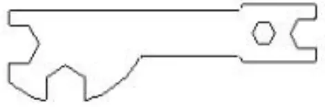
- Spanner S10-S13-S17-S19 1PC

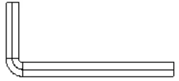
- Allen Wrench S6 1PC

- Allen Wrench S5 1PC

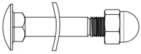
- (29)Carriage Bolt M8×40 4PCS
(30) Curve Washer ø20xø8×1.5 4PCS
(31) Cap Nut M8 4PCS
- (28) Bolt M10x20 2PCS

- (20)Axle 2PCS
(23)Wave Washer ø26xø16×0.3 2PCS
- (27)Spring Washer ø19.5xø11.5×3 2PCS

- (25)D-shaped Washer
Ø28xø16×5 2PCS - (26) Washer
ø10xø25×2.0 2PCS


ASSEMBLY INSTRUCTIONS
STEP 1: FRONT AND REAR STABILIZER INSTALLATION
Remove two M8x16 Hexagon Bolts (15) and two Ф20xФ8×1.5 Flat Washers (38) from the Front Stabilizer (7).
Remove bolts with the S6 Allen Wrench provided.
Attach the Front Stabilizer (7) onto the Main Frame (1) with removed two M8x16 Hexagon Bolts (15) and two Ф20xФ8×1.5 Flat Washers (38). Tighten bolts with the S6 Allen Wrench provided.
Remove two M8x16 Hexagon Bolts (15) and two Ф20xФ8×1.5 Flat Washers (38) from the Rear Stabilizer (8).
Remove bolts with the S6 Allen Wrench provided.
Attach the Rear Stabilizer (8) onto the Main Frame (1) with two M8x16 Hexagon Bolts (15) and two Ф20xФ8×1.5 Flat Washers that were removed (38).Tighten bolts with the S6 Allen Wrench provided.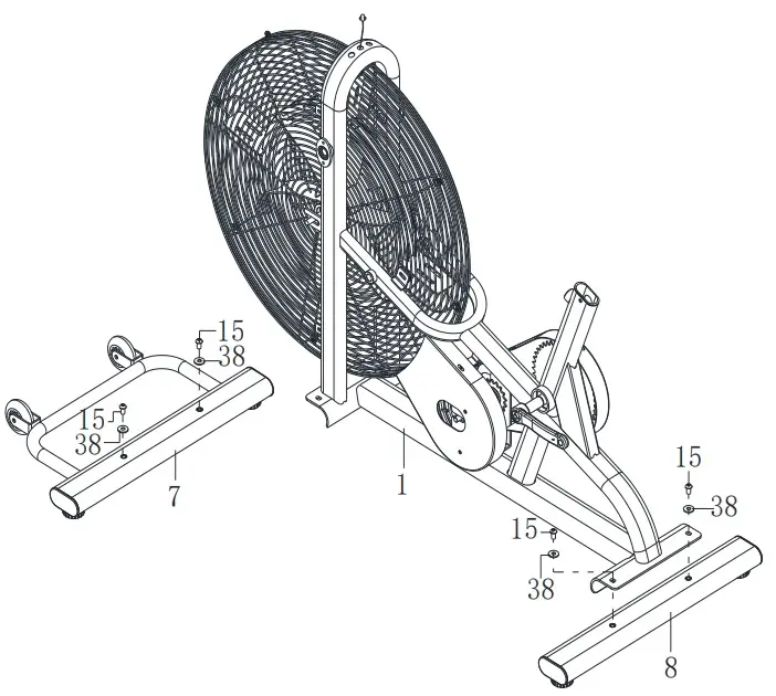
TOOLS:
Allen Wrench S6
STEP 2: HANDRAIL,FOOT BAR AND FOOT PEDAL INSTALLATION
Remove four M6x10 Bolts (22) from the Main Frame (1), and take out two Locking Plates (21). Install the Axle (20) to the Main Frame (1), tighten with Spanner provided.
Then attach two Locking Plates (21) to the Axle (20) with removed four M6x10 Bolts (22). Tighten with the Allen Wrench S5 provided.
Assemble the Handrail (5) to the Main Frame (1) with two Ф26xФ16×0.3 Wave Washers (23), two Ф28xФ16×5 D-shaped Washers (25), two Ф10xФ25×2.0 Flat Washers (26), two Ф19.5xФ11.5×3.0 Spring Washers (27) and two M10x20 Hexagon Bolts (28). Tighten with the Allen Wrench S6 provided.
Remove one Spacer (62) and Right Nylon Nut (70) from the Right Foot Pedal (61). Attach the Right Foot Bar (6) onto the right Crank (68) using Right Foot Pedal (61), one Spacer (62) and Right Nylon Nut (70). Tighten the Right Foot Pedal (61) by hand clockwise with spanner with Phillips Screwdriver provided, and tighten the Right Nylon Nut (70) counter clockwise with Spanner provided.
Repeat the same procedure to attach the Left Foot Bar (6) onto the left Crank, tighten the Left Foot Pedal (60) counter-clockwise with spanner with Phillips Screwdriver provided,and tighten the Left Nylon Nut (69) clockwise with Spanner provided.
NOTE: Do not turn the Left pedal clockwise to tighten or will strip the threads.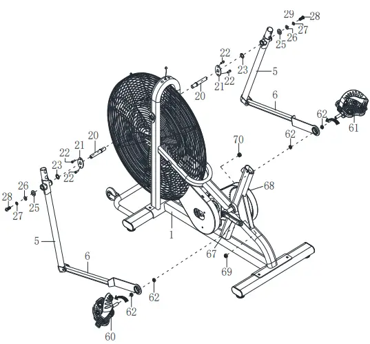
TOOLS:
- Allen Wrench S5
- Allen Wrench S6
- Spanner S10-S13-S17-S19
STEP 3: SEAT POST, FOOTREST INSTALLATION
Turn the M16x35 Adjustment Knob (81) from the Seat Post (9) in a counterclockwise direction to release the Seat Slider (10).
Then attach the Seat Slider (10) back or forth slightly to the desired hole for the suitable position. Lock the Seat Slider (10) in place by tightening M16x35 Adjustment Knob (81) in a clockwise direction.
To adjust the seat height, loosen the M16x25 Seat Height Adjustment Knob (79) on the vertical post stem on the Main Frame and pull back the Knob. Position the vertical seat post for the desired height so that holes are aligned, then release the knob and retighten it.
NOTE: When adjusting the height of Seat Post, make sure the Plastic Bushing does not Exceed the mark line on the Seat Post.
Attach the Footrest (96) onto the Main Frame (1). Tighten with the Spanner provided.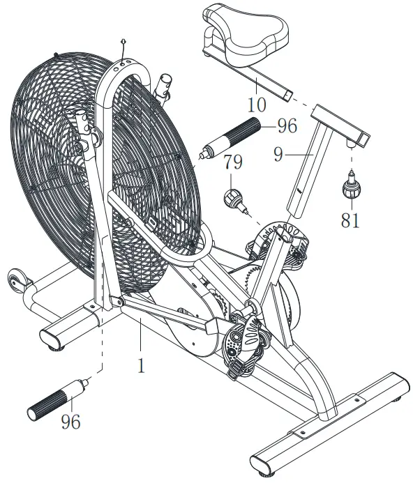
TOOLS:
Spanner![]()
STEP 4: LEFT AND RIGHT HANDRAIL ARM, METER POST INSTALLATION
Insert the Right Handrail Arm (4) on the tube of the Right Handrail (5) with two M8x40 Carriage Bolts (29), two Ф20xФ8×1.5 Curve Washers (30) and two M8 Cap Nuts (31). Repeat the same procedure to assemble the Left Handrail Arm (3).
Connect the Sensor Wire (19) with the Extension Sensor Wire (13).
Remove two M8x16 Hexagon Bolt (15) and two Ф16xФ8×1.5 Curve Washers (16) from the Main Frame (1). Attach the Meter Post (2) onto Main Frame (1) with removed two M8x16 Hexagon Bolt (15) and two Ф16xФ8×1.5 Curve Washers (16). Tighten with Allen Wrench provided.
Remove two M5x10 Cross Pan Head Screws (12) from the Computer (11). Then attach the Computer (11) onto the top end of Meter Post (2) with two removed M5x10 Cross Pan Head Screws (12). Tighten screws with the Spanner with Phillips Screwdriver provided.
Insert the pin of Extension Sensor Wire (13) into the Computer (11).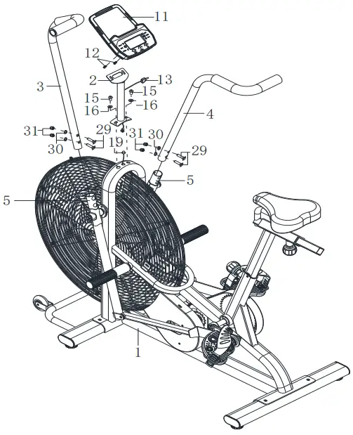
TOOLS:
- Allen Wrench S6
- Spanner with Phillips
CLEANING
The machine can be cleaned with a soft clean damp cloth. Do not use abrasives or solvents on plastic parts.
Please wipe your perspiration off the bike after each use.
Be careful not get excessive moisture on the computer display panel as this might cause an electrical hazard or electronics to fail.
Please keep the machine, especially the computer console out of direct sunlight to prevent screen damage. Please inspect all assembly bolts and pedals on the machine for proper tightness every week.
EXERCISE COMPUTER INSTRUCTION MANUAL
FUNCTIONAL BUTTONS: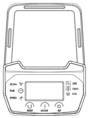
MODE – Push down for selecting functions.If the long time holds down MODE button will turn completely 0.
SET – To set the values of time,distance, pulse and calories when not in scan mode.
RESET – Push down for resetting time, distance and calories. The current data change is 0.If the long time holds down RESET, besides the ODO position, the material will turn completely 0.
FUNCTION AND OPERATIONS:
- SCAN: Press “MODE” button until “SCAN” appears, monitor will rotate through all the 6 functions:Time,speed,distance,calorie, ODO. Each display will be hold for 6 seconds.
- TIME: Count the total time from exercise start to end. Press “MODE” button until “TIME” appears, press “SET” button to set exercise time. When the “SET” is zero, the computer will alarm 10 seconds.
- SPEED: Display current speed.
- DIST: Count the distance from exercise start to end.
Press “MODE” button until “DIST” appears,Press “SET” button to set exercise distance.
When the “SET” is zero, the computer will alarm 10 seconds. - CALORIES: Count the total calories from exercise start to end.
Press “MODE” button until “CAL” appears, Press “SET” button to set exercise calories. When the “SET” is zero, the computer will alarm 10 seconds. - ODO: The total distance which this function is refers to from battery capacity period runs.
- ALARM: The computer will “Beep” when press “MODE”,“SET” and “RESET” buttons.
- AUTO ON/OFF & AUTO START/STOP
Without any signal for 4 minutes, the power will turn off automatically. As long as the wheel is in motion or press any button, the monitor is in action.
SPECIFICATIONS
| FUNCTION | AUTO SCAN | Every 5 seconds |
| TIME | 00:00’~99:59’ | |
| CURRENT SPEED | 0.0~99.9 KM/H | |
| TRIP DISTANCE | 0.00~999.9 KM | |
| CALORIES | 0.0~999.9 Kcal | |
| ODO | 0.0~999.9 KM | |
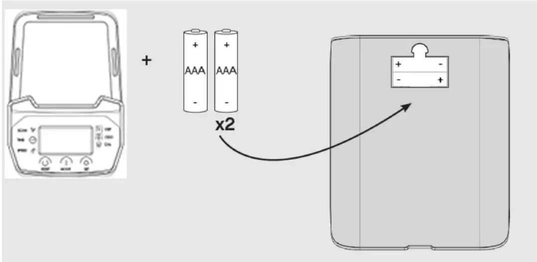
| BATTERY TYPE | 2pcs of SIZE –AAA | |
| OPERATING TEMPERATURE | 0°C ~ +40°C | |
| STORAGE TEMPERATURE | -10°C ~ +60°C | |
Note:
- If the computer displays incorrectly, please re-install the battery and try again.
- Battery Spec: 1.5V AAA (2PCS).
- The batteries must be removed from the appliance before it is scrapped and that they are disposed of safety.
- Please check the positive and negative terminals before installing the battery.

- non-rechargeable batteries are not to be recharged;
- different types of batteries or new and used batteries are not to be mixed;
- if the appliance is to be stored unused for a long period, the batteries should be removed;
- the supply terminals are not to be short-circuited.