SCHLAGE ND-Series Electrified Locks Instructions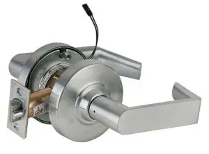
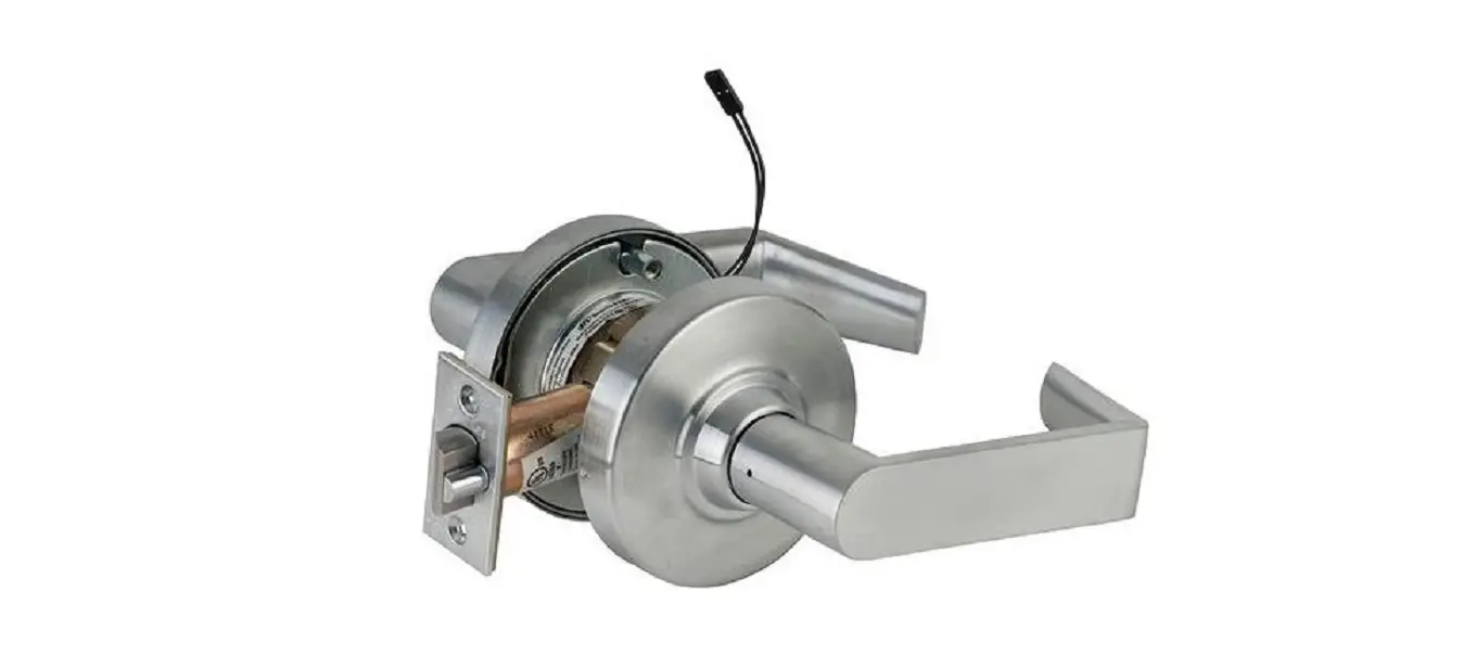
ND-Series Electrified Lock
For standard installation, see full instruction sheet.
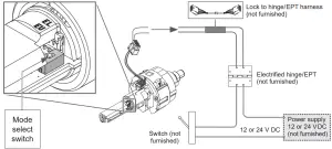
Select the appropriate mode for the installation using the mode select switch located on the chassis. Note: When mode is switched (from EL to EU or EU to EL) the lock requires a complete lock/unlock power cycle to synchronize to the proper mode.
EL, electrically locked (fail safe):
Outside knob/lever or both outside and inside knobs/levers (depending on function) will lock when power is applied. In the event of power failure, the opening will be unlocked.
EU, electrically unlocked (fail secure):
Outside knob/lever or both outside and inside knobs/levers (depending on function) will unlock when power is applied. In the event of power failure, the opening will be locked.
Electrical requirements:
The ND-Series electrified locks are powered by DC power only. DO NOT USE AC POWER.
- Voltage: 12 or 24 V DC (maximum 26.4 V, minimum 10.8 V)
- Holding current: 10 mA
- Peak current: 230 mA
- Operating temperature: 32°F to 120°F (0°C to 49°C)
- All power requirements shown are for single lock operation.
| AWG | 14 | 16 | 18 | 20 | |
Voltage | 12 V | 500’ (152 m) | 300’ (91 m) | 200’ (61 m) | 100’ (30 m) |
24 V | Up to 1000’ (304 m) | ||||
Note: Either lock wire may be attached to either power supply terminal (+ or -).
Troubleshooting:
If lock does not operate –
- Ensure the lock is powered with DC power.
- Ensure the input voltage is between 10.8 and 26.4 volts DC.
- Do not use AC power
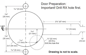
Request-to-Exit (RX) Lock
RX utilizes a microswitch inside the lock case to detect rotation of the inside knob/lever. The switch then signals the use of the opening to the security system.
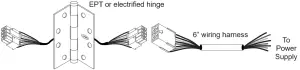
Attach wires from RX switch wire harness to an electrified hinge/EPT (not furnished). Refer to the Allegion Connect section below for wire identification. Electrical rating: 2 A, 30 V DC
RX Switch kit #N123-062 installation:
Attach switch assembly to pin on chassis using the screw (included with kit).
Use RX anti-rotation plate (see inset).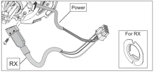
Allegion Connect
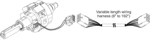
Allegion Connect, a factory-installed Molex® connector system, provides simplified installation and maintenance utilizing quick-connect harnesses and hinges. Alternatively, the Molex connector may be cut off and the lock installed with traditional wire splicing methods.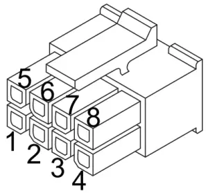
WIRE COLOR AND FUNCTION | ||
Pin | Color | Function |
1 | Black Power | (auto detects GND, +12 or +24 V DC) |
2 | Red Power | (auto detects GND, +12 or +24 V DC) |
| 3 | Purple | RX NO (normally open) |
4 | Grey | RX NC (normally closed) |
5 | White | RX COM (common for RX) |
6, 7, 8 | Not Use | |

Customer Service
1-877-671-7011
WEB: //www.allegion.com/us


