![]()
INSTALLATION &
OPERATION MANUAL
Underfloor Products
TAF-D / TAF-V / TAF-HC
TAF-R / TAF-G
LHK / PFC
LHK and PFC Underfloor Fan Powered Terminals
RECEIVING INSPECTION
After unpacking the terminal, check it for shipping damage. If any shipping damage is found, report it immediately to the delivering carrier. Store units in a clean dry location and do not stack more than four high.
Caution: Do not use the inlet collar, damper shaft, flow sensor or air tubing (available on LHK only) as a handle to lift or move assembly.
Damage to the unit or controls may result.
Before installation, remove fan packing and all foreign material from the unit. Check the blower wheel for free rotation.
FLOOR SUPPORTS
The units can be mounted directly on the slab. If isolation from the slab is necesary, the unit can be placed on a rubber or cork pad.
Access to the motor, blower,and damper assebmly is on the top of the unit. The access and control enclosure doors are sectioned so that each door is aligned with a floor panel.
Note: If equipped with pneumatic controls the terminal must be mounted right side up. It must be level within ±10 degrees of horizontal, both parallel to the air flow and at the right angle of air flow. The control side of the terminal is labeled with an arrow indicating UP.
DUCT CONNECTIONS FOR LHK
Slip each inlet duct over the inlet collar of the terminal. Fasten and seal the connection by the method prescribed by the job specification.
The diameter of the inlet duct “D” in inches must be equal to the listed size of the terminal; e.g. a duct that actually measures 8 inches must be fitted
to a size 8 terminal. The inlet collar of the terminal is made 1/8” smaller
than listed size in order to fit inside the duct.
Important: Do not insert duct work inside the inlet collar of the assembly.
Inlet duct should be installed in accordance with SMACNA guidelines.
Rectangular discharge opening is designed for flanged duct connections.
Fasten and seal by method prescribed in the job specification.
If single-point electronic velocity sensor is used, 3 to 5 inlet duct diameters of straight duct should be provided at the terminal inlet.
MINIMUM ACCESS
Fan Powered terminals require sufficient clearance to service the fan blower assembly, low voltage controls and line voltage motor controls or electric heat section from the top of the unit.
For top access panel removal, 2” minimum vertical clearance above the unit is recommended, plus sufficient horizontal clearance to slide the access panel clear of the top of the unit. Horizontal clearance is dependent on access panel dimensions as indicated on product submittals.
Low voltage control enclosure doors are “L” shaped to allow access from the top and sides. For low voltage control enclosure access, a minimum of 18” clear is recommended. Specific control enclosure location is indicated on product submittals. Panel for low voltage enclosures are removable (not hinged). For line voltage motor controls or electric heat control access, a minimum of 36” should be provided to allow full opening of hinged access doors. Specific location is indicated on product submittals.
Important: These recommendations do not preclude NEC or local codes that may be applicable, which are the responsibility of the installing contractor.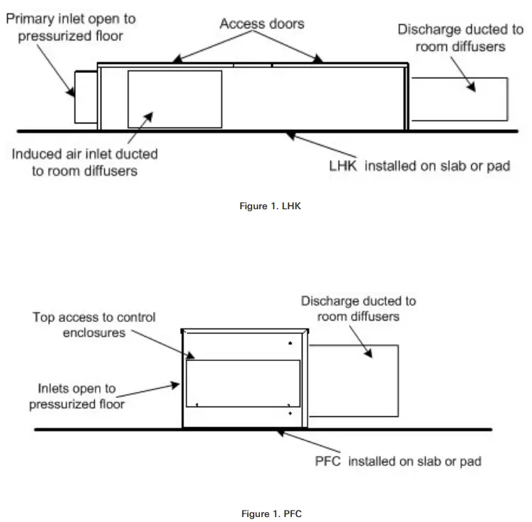
Field Wiring
All field wiring must comply with the local codes and with the National Electrical Code (ANSI/NFPA 70-1996). Disconnect switches are optional equipment. Electrical, control, and piping diagrams are shown on the exterior labeling or on a diagram on the inside of the control and high voltage enclosure covers. Unless specified otherwise in the order write-up, all units are wired for a single point electrical connection to the fan and optional electrical heater. All electric heaters if provided by Titus are balanced by kW per stage. The installing electrician should rotate incoming electric service by phase in order to help balance the building electric load.
Caution—Electrical Requirement:
- Provide a safety disconnect per NEC 424-19, 20 & 21.
- Disconnect all incoming power before wiring or servicing unit. All disconnect switches on the terminal (if so equipped) should be in OFF position while making power connections.
- All field wiring must be in accordance with NEC and local code requirements. All units with electric heat should have copper wires for 125% of Nameplate Amperage.
- Observe wiring diagram and instructions mounted on the unit. 480 V/3 phase units require a 4th (neutral) wire in addition to the full sized ground wire. All units must be grounded as required by NEC 424-14 and 250.
Unit Labeling
Each unit will have two main labels attached to the casing. The FAN UNIT label (Figure 3) lists the Model Number, Supply Voltage requirements, Motor Horsepower, and Overcurrent Protection requirements. The AIR FLOW label (Figure 4) lists the Model Number, Unit Size, Factory Order Number, and Location. The Location (or “Tag”) indicates the engineer’s planned location for the unit to be installed. There may be other labels attached to the unit, as options or codes may require.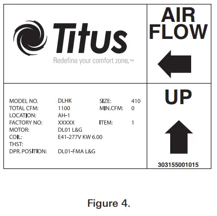 Please read all labels on a typical unit, before beginning installation.
If you have any questions, please contact the local Titus Representative for clarification. Have the key points from the AirFlow label available for reference before calling.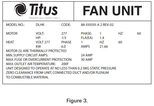
Control Start-up, Operation
Detailed information regarding power, accessory and communications connections, start-up and operating procedures for the Titus TD-1 controller (digital) or pneumatic and analog controls are available from your local Titus representative. For specific information on controls by other manufacturers contact that manufacturer’s local branch or dealer.
Note: Controllers may incorporate specific communication addresses based on Building Management Systems Architecture, and original engineering drawings. Installing the terminal in a different location than noted on unit label may result in excessive start-up labor.
Fan Flow Adjustment
Note: Before starting fan motor, follow steps 1 and 2.
- Discharge ductwork should be connected. The minimum recommended discharge static pressure is 0.2” wg. Be sure fan packing is removed!
- All foreign materials should be removed from duct system. Filters should be installed where required.
- Motor is shipped from factory at full speed setting. Allow motor to run-in at least 15 minutes before adjusting speed. During initial run-in, check ductwork connections for leaks and repair if necessary. (Do not adjust fan speed down if ductwork is not connected).
- Unit is equipped with manual fan speed control, mounted on the side of the line voltage motor enclosure. Turning the control counterclockwise will reduce the fan speed; clockwise will increase speed.
- Set the unit to full heating (maximum induction). Adjust and set remote balancing dampers, if present. Adjust the speed control to deliver the required CFM by measuring air quantity at the room outlets.
- Proceed to primary air adjustment procedure (LHK only), detailed in control installation information. Fan should be re-adjusted with primary air and ventilation air at maximum setpoint, to insure that no supply air is discharged at the induction port.
Maintenance Procedures, Fan and Motor
Motor is equipped with permanently lubricated bearings. Inspect fan and motor assembly for accumulation of dust and dirt as required by operating environment. Clean as necessary.
If fan motor does not run:
a. Free rotation of blower wheel fan packing removed. freight or installation damage.
b. Check for proper unit power Disconnects should be ON. Check optional fusing.
c. Check for proper control signal, P/E switch setting, proper air control 24 vac at fan contactor, coil energized.
If fan motor runs, excessive noise:
a. Clearance problems on blower. All components securely attached.
b. Verify integrity of ductwork. Leaks or loose connections. Rattling diffusers or balancing dampers.
c. Maximum CFM too high, or discharge static pressure too low
If fan motor runs, insufficient airflow:
a. Check for ductwork restrictions. Dirty air filters. Clogged water coils.
b. Re-adjust fan speed control.
c. Discharge static pressure too high.
If repair or replacement is required:
Motor and fan should be removed as an assembly. Disconnect all power before servicing. Remove the four hex nuts from the mounting lugs holding the fan assembly to the discharge panel, and lower the assembly. Do not allow assembly to hang from wiring.
If removing motor from blower, first loosen the set screw holding the blower wheel to the motor shaft. Remove the three screws holding motor to the fan housing, and slide motor and fan housing apart.
Reverse the procedure for assembly.
Note: Over tightening motor mounting screws may crush isolation bushings, causing excessive fan noise.
Primary Air Damper
LHK MODEL:
To replace the damper blade and/or shaft assemblies:
a. Disconnect power before servicing. Remove control enclosure cover to access actuator.
b. Note position of damper shaft, using indicating arrow. Loosen linkage or actuator collar to allow damper to rotate freely.
c. Remove bottom access door to expose damper assembly. Rotate damper to fully closed position, exposing rivets holding damper blade to shafts.
d. Drill out rivets using 1/2” drill, rotate damper to fully open position, and slide damper and/or shaft assemblies out of the duct.
e. Fit new damper and/or shaft assemblies in place, using 1/4-20 screws with lock nuts to replace rivets.
f. Reverse procedure in steps c, b, and a, for assembly. When locking down actuator linkage or collar, position indicating arrow on damper in the same location as before the repair.
Replacement Parts List
| Description | Part Number |
| Multipoint Velocity Sensors | |
| Size 9” | 3151520005 |
| Size 10” | 3151520006 |
| Damper Shaft Bearing | |
| Shaft Bearing – All | 70324901 |
| Primary Damper Assembly (LHK) | |
| Size 9 | 31171304 |
| Size 10 | 31171305 |
| Unit Size | Filter Size | Part Number |
| Induced Air Filters | ||
| Model LHK | ||
| 3 | 18 x 10 | 1.03E+09 |
| 4 | 18 x 14 | 1.03E+09 |
| Model PFC | ||
| 10 | 18 x 10 | 1.03E+09 |
| 14 | 16 x 14 | 1.03E+09 |
| 16 | 14 x 16 | 1.03E+09 |
| Control Tube | ||
| Red Stripe .25” O.D. | 61510035 | |
| Green Stripe .25” O.D. | 61510034 | |
| Red Stripe .38” O.D. | 61510279 | |
| Green Stripe .38” O.D. | 61510280 | |
| Tees for Sensor Taps | ||
| Plastic .25” | 42150011 | |
| Plastic .38” | 42150020 | |
| Description | Part Number |
| Plugs for Tees | |
| .25” | 42160081 |
| .38” | 10015601 |
| Fan Motor Fuse (SC-CL-G 300V) | |
| 1 Amp | 10048301 |
| 3 Amp | 10048501 |
| 4 Amp | 10048601 |
| 6 Amp | 10048801 |
| 8 Amp | 10049001 |
| 10 Amp | 10049101 |
| 12 Amp | 10049201 |
| 15 Amp | 10049301 |
| 20 Amp | 10105201 |
| Disconnects | |
| Fan Toggle (All) | 10027801 |
| Door Interlock 3P/40A (All) | 10053201 |
| Door Knob 40 Amp | 100532011 |
| Door Interlock 3P/80A (All) | 10054601 |
| Door Knob 80 Amp | 100546011 |
| Fan Relays | |
| 1 Pole, 24V Coil | 10156901 |
| 2 Pole, 24V Coil | 10161801 |
| Contactors, Magnetic | |
| 2P/20A, 24V coil | 10054401 |
| 2P/20A, 120V coil | 10054402 |
| 2P/20A, 208/240V coil | 10054404 |
| 2P/20A, 277V coil | 10054403 |
| Safety Devices | |
| AutAuto Reset Thermal Cutout for Elec. Coils o Reset Thermal Cutout | 10052101 |
| Air Flow Switch (AFS) | |
| AFS Sensor 4” length 10057201 | |
| AFS Sensor 6” length 10057202 | |
| P.E. Switch, 1 step | 10000901 |
| P.E. Switch, 2 step | 10199801 |
| P.E. Switch, 3 step | 10199802 |
| Control Transformers | |
| 120/24V, 50 VA | 10029301 |
| 208/240/24V, 50 VA | 10057501 |
| 277/24V, 50 VA | 10006601 |
| Fan Speed Controllers (SCR) | |
| 120V | 10055301 |
| 208/240V | 10057601 |
| 277V | 10053301 |
| Fan Motor Capacitors (120V,208/240V, 277V) | |
| 1/4 Hp Motor 5 MFD | 10053002 |
| 1/3 Hp Motor 10 MFD | 10053003 |
| 3/4 Hp Motor 20 MFD | 10055701 |
| Mounting Bracket (all) | 10054501 |
| ECM Motor Components | |
| ECM Motor Mounting Assembly | 31484401 |
| PWM (Manual Operation) | 10334801 |
| PWM (Remote Operation) | 10334801 |
| 277V Power Cable, 8 ft. | 10320501 |
| 277V Power Cable, 5 ft. | 10320520 |
| 24V Comm. Cable, 8 ft. | 10334901 |
| 24V Comm. Cable, 5 ft. | 10334902 |
| LHK Inductor | |
| 277V: Inductor 3.0 Amp (Size 3) Inductor 5.5 Amp (Size 4) 10335001 | 10335101 |
| 120V: Inductor 11 Amp (All) | 10348001 |
| PFC Inductor | |
| 277V: Inductor 5.5 Amp (All) | 10335001 |
| 120V: Inductor 11 Amp (All) | 10348001 |
Fan Motors
| Model | Unit Size | HP | 120V/1 | 208/240V/1 | 277V/1 | Blower Assembly |
| LHK | 3 | 4-Jan | 10095303 | 10150103 | 10096703 | 10045501 |
| PFC | 4 | 3-Jan | 10151201 | 10151203 | 10151202 | 10045501 |
| 10 | 4-Jan | 10095303 | 10150103 | 100967-03 | 10045001 | |
| 14 | 3-Jan | 10151201 | 10151203 | 10151202 | 10346201 | |
| LHK | 16 | 4-Mar | 10051401 | 10057003 | 10051402 | 10261701 |
| w/ECM | 3 | 3-Jan | 31535224 | N/A | 31535209 | 10045501 |
| Motor | 4 | 3-Jan | 31535225 | N/A | 31535210 | 10045501 |
| PFC | 10 | 3-Jan | 31535234 | 3.15E+08 | 31535233 | 10045001 |
| w/ECM | 14 | 2-Jan | 31535226 | 3.15E+08 | 31535211 | 10346201 |
| Motor | 16 | 1 | 31535227 | 3.15E+08 | 31535212 | 10261701 |
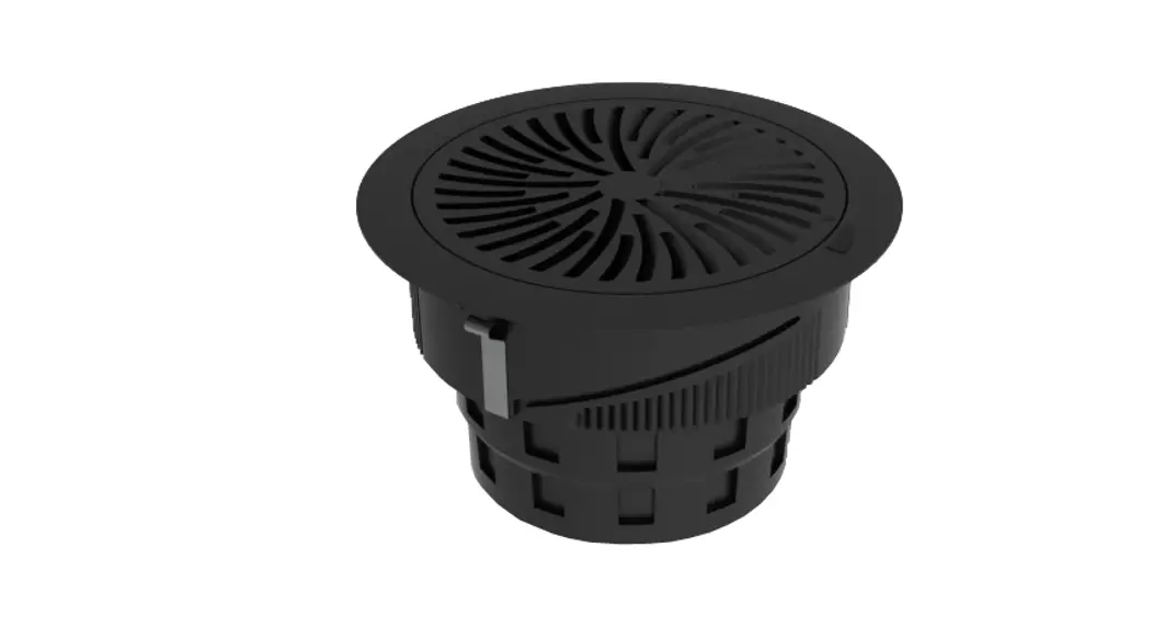
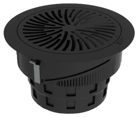
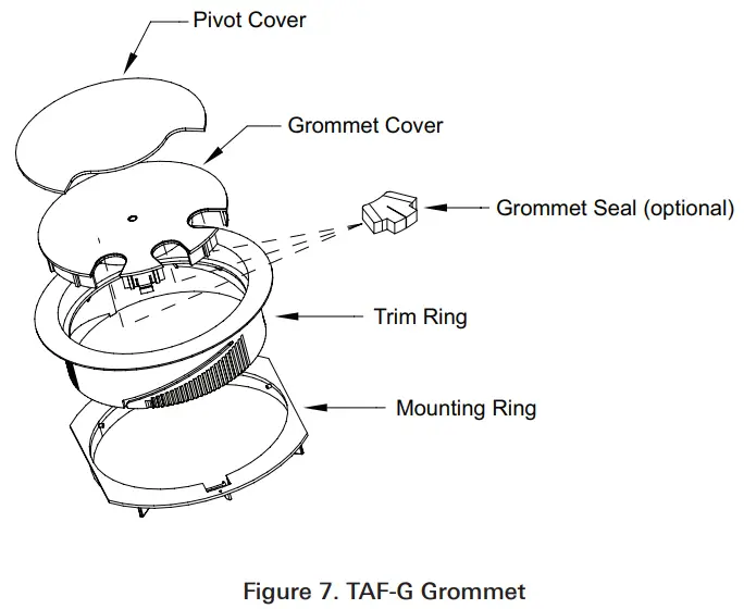
TAF-R Diffusers and TAF-G Grommet
The TAF-R diffuser and TAF-G grommet were designed to install easily in the floor without the need to remove the floor tile. The TAF-R and TAF-G should be installed after the installation of carpet. The TAF-R and TAF-G install using the mounting ring spring clip assembly.
Installation requires a 8 5/8” mounting hole cut into the access floor tile. It is recommended that the tile is pre-cut from the tile manufacturer to ensure a consistent, round 8 5/8” hole.
Note: The trim ring should be able to move freely in the mounting hole.
Irregular shaped holes may bind the trim ring and force it to not properly seat in the mounting hole.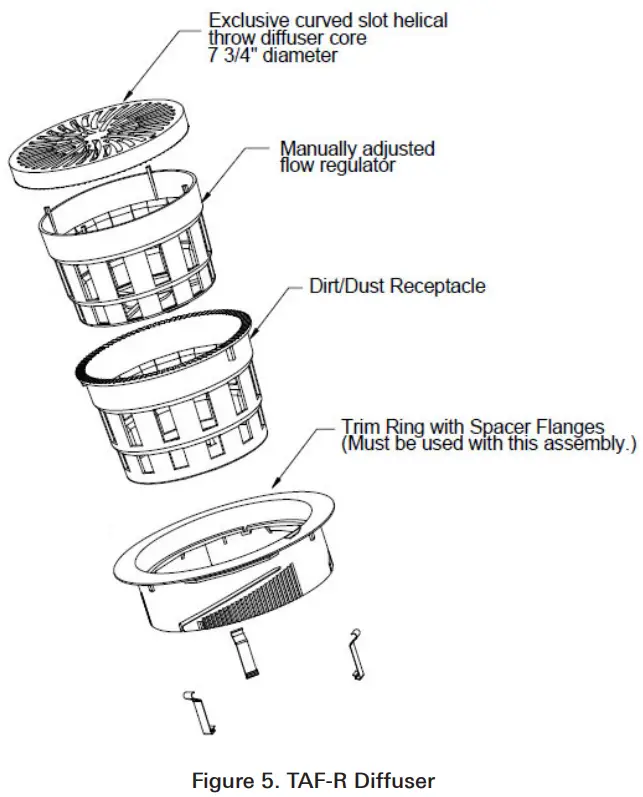
 Place trim ring above the mounting hole. Press the trim ring into the floor by using your weight to press down on the trim rings so the clips engage below the floor tile (Figure 8).
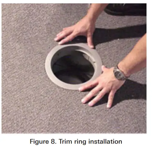 Place the inner damper basket in the outer dirt basket and insert the baskets into the trim ring (Figure 9). The outer basket has three tabs which are keyed to the trim ring so that the baskets will only install flush in one position.
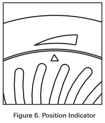
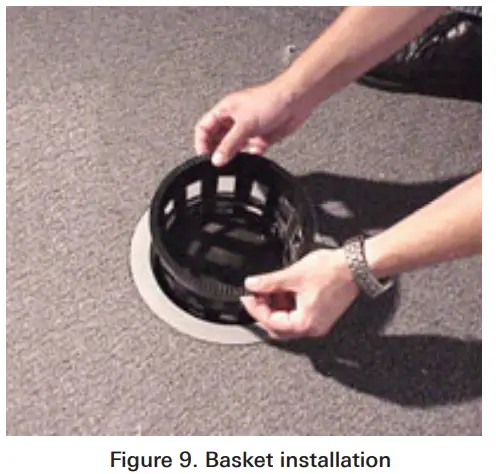 For the TAF-R, place the diffuser in the trim ring (Figure 8) and align the open / closed position indicator (Figure 6). For the TAF-G, snap the grommet cover into the trim ring (not shown).
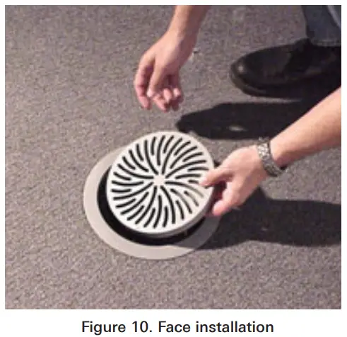 For the TAF-R with the optional actuator, the actuator interconnect diagram can be seen on page 12 of this document.
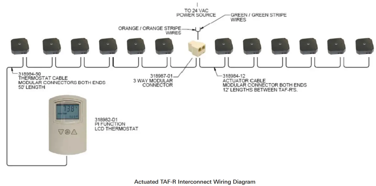
Actuated TAF-R Interconnect Wiring Diagram
Note:
- All referenced part numbers in the interconnect diagram below can be found on the TAF-R ordering procedure
- A maximum of six actuators may be daisy chained between the thermostat and transformer. After that, a maximum of six more actuators may be daisy chained on the opposite side of the transformer. A maximum of 12 actuators may be supplied from one transformer and controlled from one thermostat.
- The transformer must have an internal circuit breaker or equivalent breaker or equivalent 2.25A external fuse in the secondary circuit.

Replacement Parts List (See pages 13-15 for interconnect part details)
| Part Number | Description |
| 31898201 | Thermostat for Actuated Flow Regulator |
| 72541702 | TAF-R Black Grille |
| 10304502 | TAF-R Black Trim Ring |
| 10304602 | TAF-R Black Flow Regulator (Inner Basket) |
| 10304802 | TAF-R Black Dust Basket (Outer Basket) |
| 72541701 | TAF-R Grey Grille |
| 10304501 | TAF-R Grey Trim Ring |
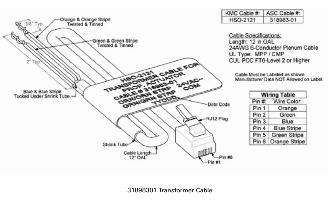
| 31898301 | Transformer Cable RJ12 Length (12in) |
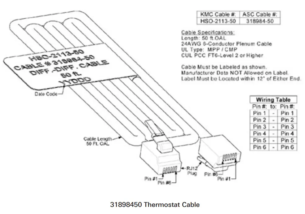
| 31898450 | Thermostat Cable Length (50 ft) |
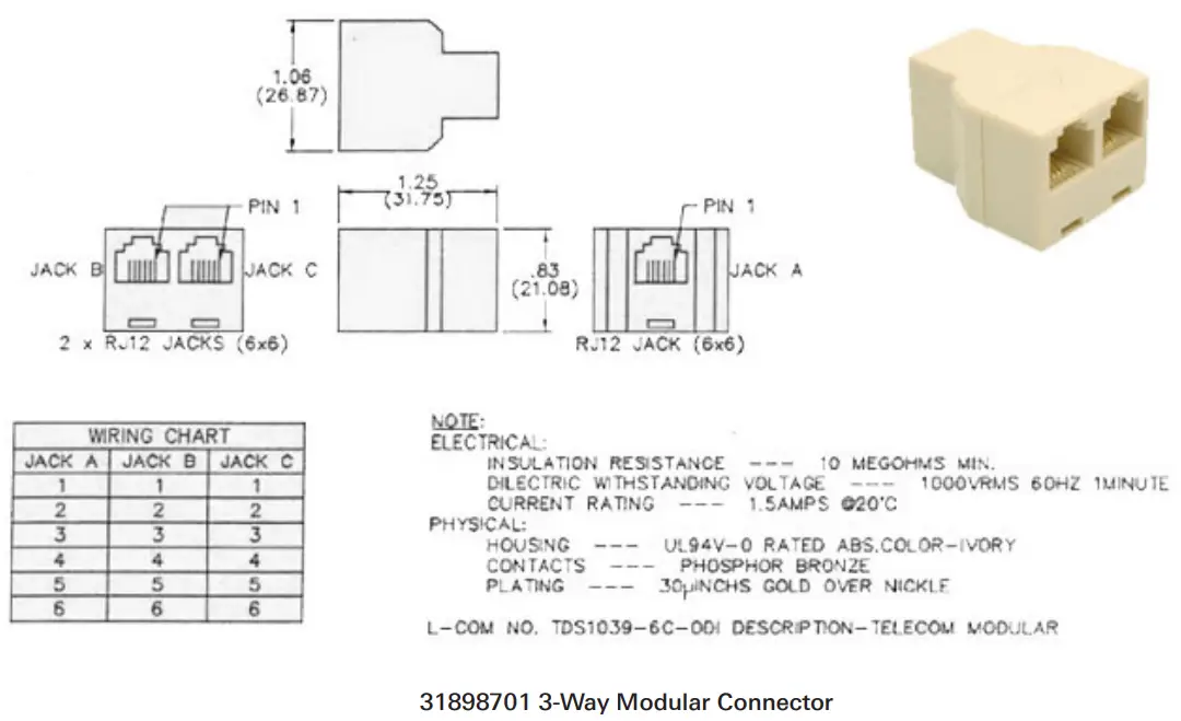
| 31898701 | 3-Way Modular Connector |
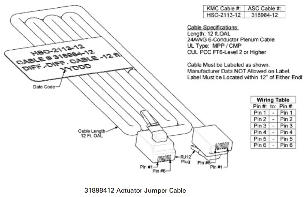
| 31898412 | Actuactor RJ12 Jumper Cable Length (12 ft) |
Actuated TAF-R Interconnect Components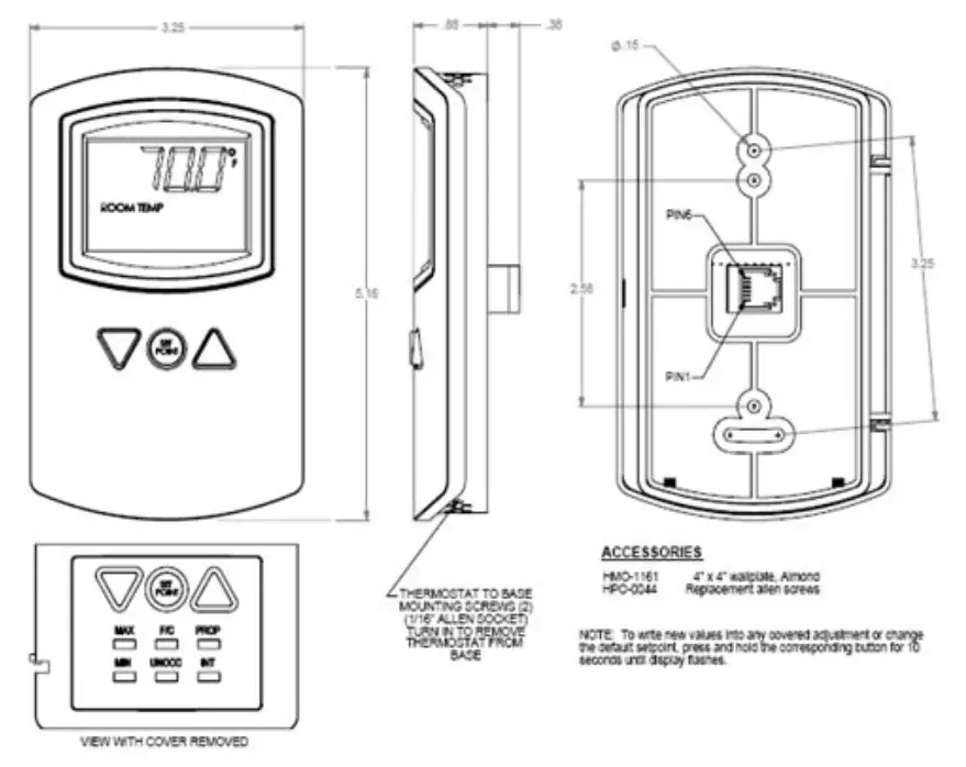
- Specifications
- Supply Voltage: 14-19 VDC
- Set Point Range: 60-85F (15.6-29.4C) (Power on Default: 70F/21.1C)
- Temperature Sensor Type: Thermstor
- Accuracy: +/- 36F (2C)
- Display Degrees F or C: Selectable (Factory Setting: Degrees F)
- Direct Acting Output: 0-10 VDC
- Min/Max Limits: Adjustable 0-100% (Factory Settings: Min = 20, Max = 100)
- Proportional Band: 2-6F (1.1-3.3C) (Factory Setting: 4F)
- Integration Time: 15-60 Minutes (0 = Off) (Factory Setting: 30)
- Unoccupied Setpoint Modes: Off or Deadband (Factory Setting: Off)
- Off Mode: Output Voltage = 0.0 Volts (Safety Override: Output Cycles 0.0 Volts to 2.0 Volts to maintain 50F to 55F)
- Deadband Mode: Integral Action Disabled & Setpoint set to default +/- 10F Deadband. Deadband output midway between max. & min.
- Temperature Offset: Adjustable +/- 2F (+/- 1.1C) (Press min & int together)
- Operating Ambient: 34-125F (1.1-51.6C)
- Shipping Ambient: -40-140F (-40-60C)
- Humidity: 0-95% non condensing
- Case Material: Light almond abs, UL Flame Class 94HB
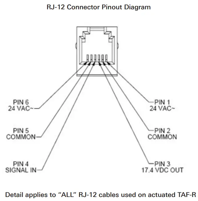
- RJ-12 Female Connector:
PIN1 NC……… PIN2 COM…………… PIN3 SUPPLY
PIN4 OUT………….. PIN5 COM ………….PIN5 NC


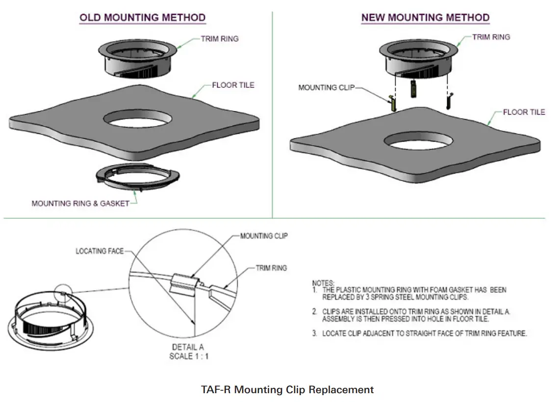
TAF-R Mounting Clip Replacement
 Note:
Note:
- “Old Mounting Method” detail above illustrates the previous installation method of the TAF-R which utilized a mounting ring & gasket as shown in the above view. The mounting ring & gasket can be discarded in place of the new mounting clips shown in the “New Mounting Method” view above.
- Detail “A” shows the location for the replacement clip. There are 3 slotted features on the trim ring that will require the replacement clip be located adjacent to this slotted feature as shown in Detail “A”.
- The mounting clip replacement part number is 72821301. This part number should be ordered for a quantity of 3 clips per unit being replaced. For example, if 5 TAF-R units need to have the mounting ring & gasket replaced, then a quantity of 15 clips should be ordered.
TAF-HC, TAF-D and TAF-V Diffusers with Plenum
The TAF-HC, TAF-V and TAF-D diffuser plenums were designed to install easily in the floor without the need to remove the floor tile.
Installation requires a 8 5/8” by 16 5/8”mounting hole cut into the access floor tile.
Attach the CT-TAF grille frame to the TAF-HC / TAF-V / TAF-D plenum using sheet metal screws prior to installation in the floor. For the TAF-HC and TAV-V, the actuator and thermostat must be wired before the unit is installed in the floor tile. Once the CT-TAF frame is attached to the plenum, slide the assembly into the hole in the floor tile. (Figure 11).
The wiring for the TAF-HC and TAF-V is shown in (Figure 12). 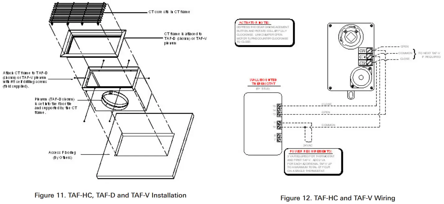

![]() 605 Shiloh Rd
605 Shiloh Rd
Plano TX 75074
ofc: 972.212.4800
fax: 972.212.4884
Redefine your comfort zone. ™
www.titus-hvac.com


