![]()
![]() ASSEMBLY INSTRUCTIONS
ASSEMBLY INSTRUCTIONS
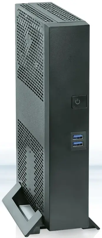
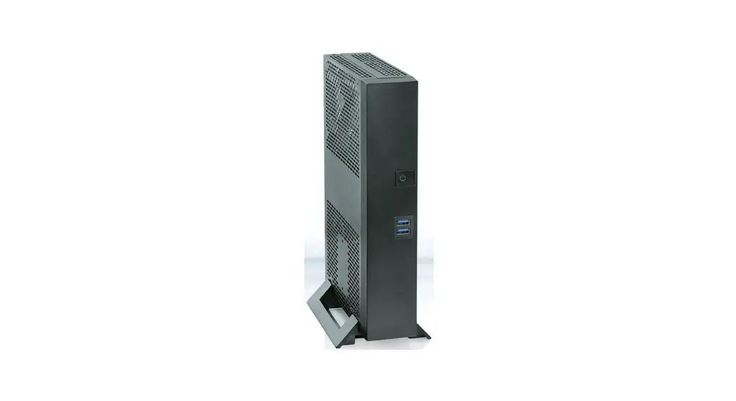
SMARTCASE™ S7xx with Front USB
Technical data are subject to change without prior notice. Kontron accepts no responsibility with regard to technical or editorial mistakes or omissions.
SMART CASE S7xx: Model Overview
| SMARTCASE | Supported Motherboard | Note |
| S700 Datasheet | D3543-Sx Intel GeminiLake | DC-IN: 8V-36V (5A max./65W max.) via external motherboard connector Compliance with IEC 62368-1 according to clause 6.2.2. to power source category PS2 (“Limited Power Source”) required! Optional: Integrated PSU module F5000-P004 (Input 100-240V; Output 12V/65W) ftp://ftp.kontron.com/Products/Accessories/PSU_AC-Adapter/F5000-P004_Internal-PSU-Kit_12V@65W/[email protected] |
| S711 Datasheet | D3713-Rx D3713-Vx AMD Ryzen Embedded | DC-IN: 8V-36V (5A max./65W max.) via external motherboard connector Compliance with IEC 62368-1 according to clause 6.2.2. to power source category PS2 (“Limited Power Source”) required! Optional: Integrated PSU module F5000-P004 (Input 100-240V; Output 12V/65W) ftp://ftp.kontron.com/Products/Accessories/PSU_AC-Adapter/F5000-P004_Internal-PSU-Kit_12V@65W/[email protected] |
| S720 Datasheet | D3433-S D3434-S Intel SkyLake/KabyLake D3633-S D3634-S Intel CoffeeLake | DC-IN: 12V (5A max./60W max.) via DC-In connector integrated into S720 chassis (includes an EMI filter for 12V supply voltage) |
This document covers the following chassis versions:
- SMART CASE S700 Rev. 02
- SMART CASE S711 Rev. 02
- SMART CASE S720 Rev. 02
Delivery Kit & Accessories: Screw Overview
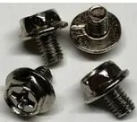
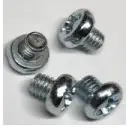
Assembly Screws
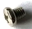
| Type | Amount | Mandatory Assembly Torque | Note |
M2.5 x 4mm
| 4 | 0.4Nm | for wall mount bracket assembly (delivered in a plastic bag) |
M2.5 x 5mm
| 4 | 0.4Nm | for chassis foot assembly (delivered in a plastic bag) |
M3 x 4.5mm
| 4 | 0.6Nm | for motherboard assembly (delivered in a plastic bag) |
| 2 | for chassis top cover assembly (delivered in a plastic bag) | ||
| 1 | for assembly of optional internal PSU module to crossbar (F5000-P004) (delivered in a plastic bag) | ||
| 1 | for assembly of DC-plug holder (delivered in a plastic bag, SC-S700/SC-S711 only) | ||
| 1 | for assembly of drive/fan carrier (pre-installed in chassis kit) | ||
| 1 | for assembly of the crossbar (riser cardholder) (pre-installed in chassis kit) | ||
| 1 | for assembly of PCIe slot bracket (pre-installed in chassis kit) | ||
M3 x c3mm
| 4 | 0.25Nm | for 2.5” drive/SSD assembly (delivered in a plastic bag) |
M3 x 3.2mm
| *) | 0.2Nm | Screw for M.2 SSD/WLAN module assembly (pre-installed on the motherboard) |


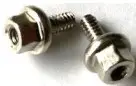
M3 x 3mm
| *) | 0.3Nm | Hexagon bolt (“assembly nut”) for M.2 SSD module assembly (pre-installed on the motherboard) |
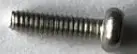
M2 x 7.5mm
| *) | 0.25Nm | Screw for Mini-PCIe module assembly (pre-installed on the motherboard) |
COM screws UNC4-40
| 2 | 0.6Nm | Screw for optional COM cable (included in cable kit F5000-K005/-K010) |
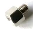
M8 x 0.75mm
| 1 | 0.6Nm | Screw nut for DC-In connector (pre-installed on the motherboard; SC-S711/D3713 only) |

*Amount depends on motherboard model
Note: Actual screw models may differ from the pictures shown above!
Step 1 Preparing the Chassis
The chassis top cover can be removed w/o uninstalling any screws, just slide the top cover forward and then pull it forwards.
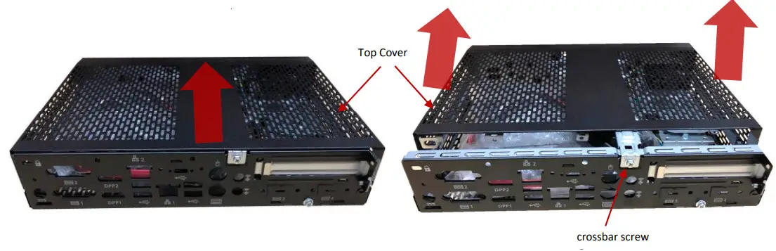
After removing the top cover:
- Unpack the accessories (content depends on the SMART CASE S7xx model).
- Remove the crossbar (“riser cardholder”) screw and remove the crossbar carefully
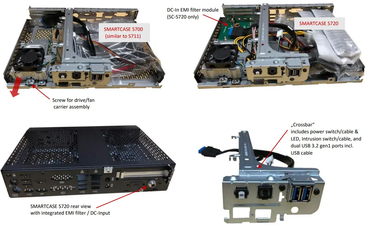
- Remove the drive/fan carrier screw and remove the carrier by sliding it to the front
Step 2 Motherboard Assembly
Note: Before assembling the motherboard into the chassis, it’s recommended to install the optional onboard components like processor, heatsink, memory, M.2 modules, etc.
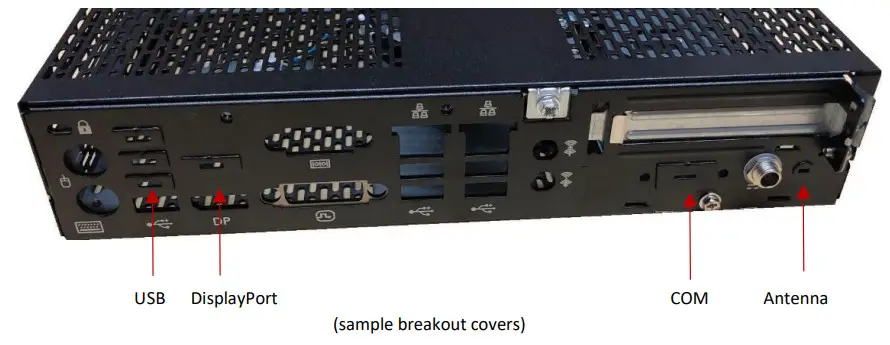
The SMART CASE S7xx chassis provides several breakout covers for the rear I/O connectors, which must be removed before inserting the motherboard, additional COM-ports, or a WLAN antenna.
Make sure to remove the appropriate covers, dependent on the motherboard version.
An appropriate screwdriver is recommended for removing these covers.
- Slide in the motherboard carefully towards the rear I/O apertures
- Move the motherboard carefully down to the final position
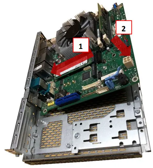
Push down the motherboard carefully while the four mounting holes fit onto the chassis nuts.
Assemble the red marked four mounting screws M3 x 4.5.
Mandatory torque = 0.6Nm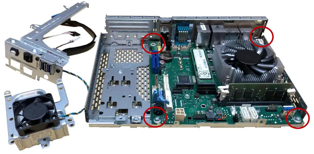
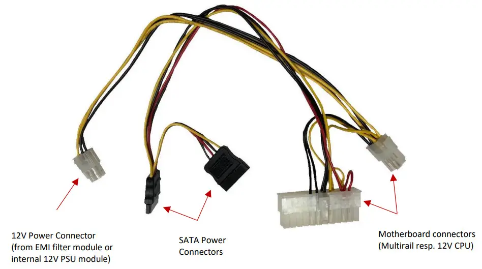
• Usage of internal power cable (SMART CASE S720 only)
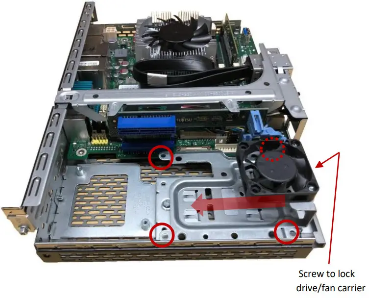
Step 3: Installing Riser Card and HDD/SSD (optional)
Insert the optional riser card before assembling the drive/fan carrier.
The drive/fan carrier provides 4 mounting holes (red circles) in order to assemble a 2.5” drive or SSD.
Use the four M3 x 3.0 screws and plug in the SATA/Power connectors. (Mandatory screw torque = 0.25Nm)
Lock the drive/fan carrier with an M3 x 4.5 screw. (Mandatory torque = 0.6Nm)
Step 4: Installing internal DC-In Module (optional)
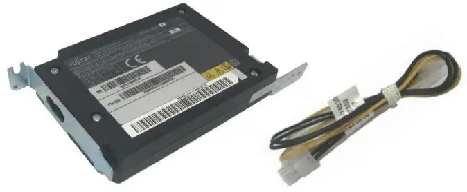
(DC-In Module F5000-P004 with internal power cable)
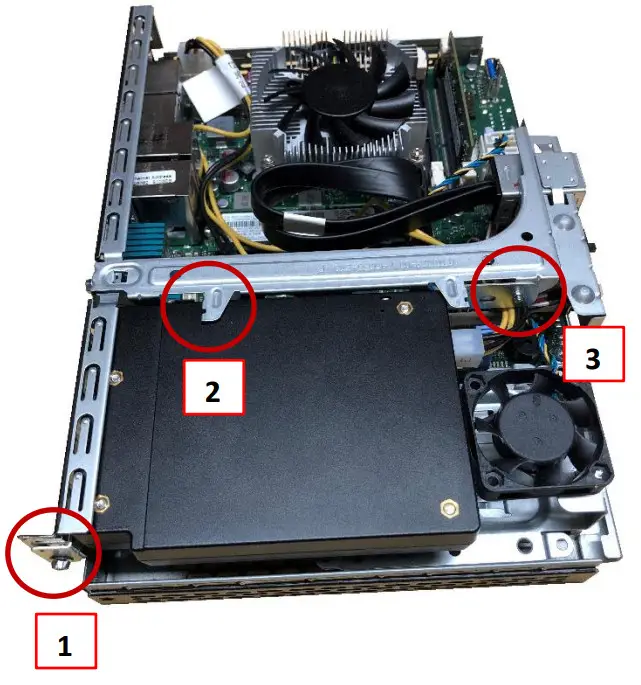
1) Remove PCIe slot bracket and insert DC-In module
2) Hook of the crossbar must fit the recess of the DC module
3) Fix metal sheet of DC module to the crossbar by screw
4) Connect the internal power cable between DC module and motherboard (internal DC-In connector)
Note: For SC-S720 specific internal power cable (included in the chassis kit) has to use. Instead of the filter module, the DC-In module has to be connected.
5) In order to avoid any misuse, the external DC-In connector of the motherboard respectively DC-In filter (SC-S720) should be closed by the rubber included in F5000-P004
Assembly screws for #1 and #3: M3 x 4.5
(Mandatory torque = 0.6Nm)

Step 5 Crossbar & Front USB Assembly
In order to assemble the crossbar, connect the power button cable and intrusion cable of the crossbar to the appropriate connectors of the installed motherboard (see motherboard TechNotes document for connector details).
Install the USB cable of the crossbar to the appropriate USB 3.2 gen1 connector of the motherboard. Consider the cable routing; severe kinking of the USB cable must be avoided.
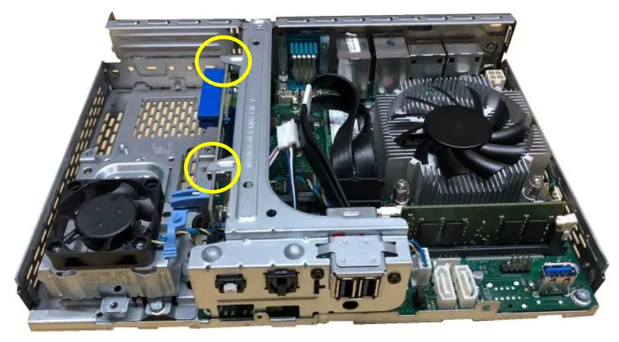
Position the crossbar on the chassis. Consider the correct locking of the riser card, if installed (yellow circles)
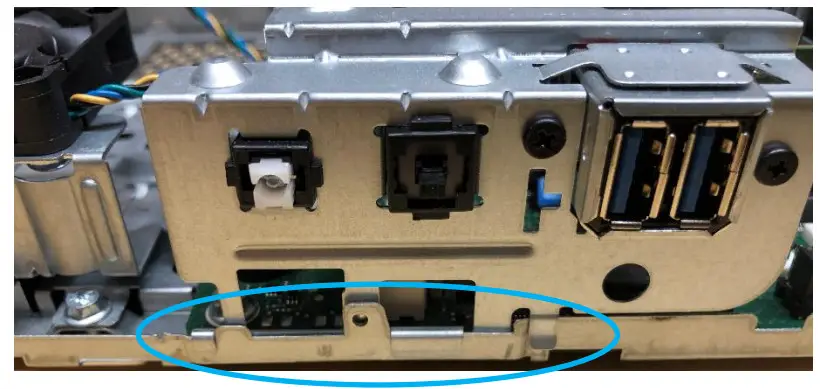
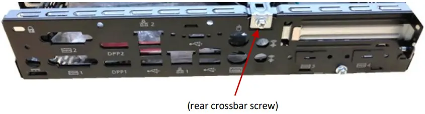
Take care of the correct position of the crossbar front hooks (blue circle), and install the rear crossbar screw M3 x 4.5mm.
(Mandatory torque = 0.6Nm)
Step 6 Closing the Chassis
Slide the cover on top of the chassis while pushing it backward.
Some slight pressure may be required.
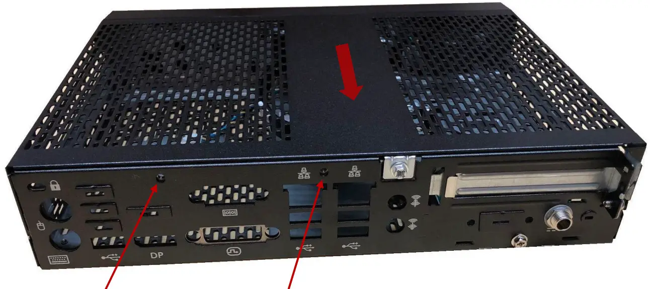
Close the chassis cover using two screws (M3x4.5) included in the SMART CASE chassis kit.
Mandatory torque: 0.6Nm
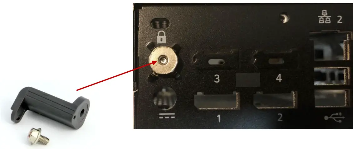
For SMART CASE S700 or SMART CASE S711, the DC-In lock can be installed; screw M3x4.5
Mandatory torque: 0.6Nm
Step 7 Adding Stands (Chassis Feet)
- The stands included in the chassis kit can be used for horizontal or vertical chassis operation
- The feet are assembled by snap-in plastic notches while gently pressing the two lockings (consider snap-in direction as shown below).
- Secure the stands with four screws M2.5 x 5. Mandatory torque: 0.4Nm
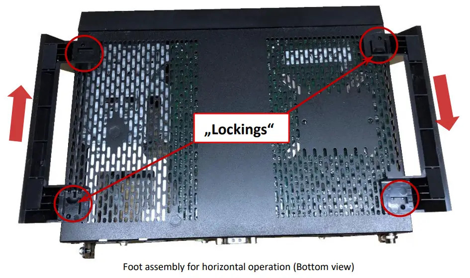
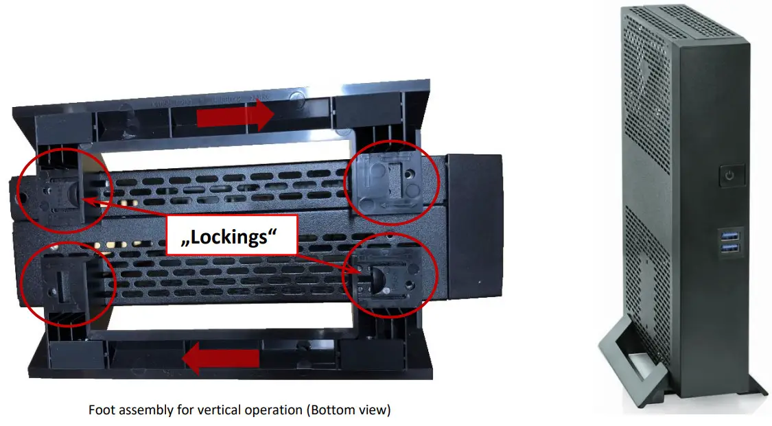
Note: Vertical operation is supported in shown orientation only (upside-down not possible)
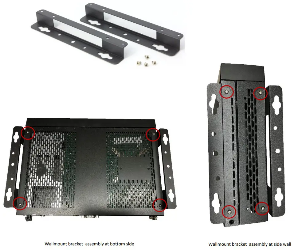
Step 8 Adding Wallmount Brackets
The chassis kit includes two wall mount brackets for horizontal or vertical use, which are assembled by four screws M2.5 x 4.
Mandatory torque: 0.4Nm
![]()
About Kontron
Kontron is a global leader in IoT/Embedded Computing Technology (ECT). As a part of the technology group S&T, Kontron, together with its sister company S&T Technologies, offers a combined portfolio of secure hardware, middleware, and services for Internet of Things (IoT) and Industry 4.0 applications. With its standard products and tailor-made solutions based on highly reliable state-of-the-art embedded technologies, Kontron provides secure and innovative applications for a variety of industries. As a result, customers benefit from accelerated time-to-market, reduced total cost of ownership, product longevity, and the best fully integrated applications overall.
For more information, please visit: www.kontron.com
![]()
Global Headquarters
Kontron Europe GmbH
Gutenbergstraße 2
85737 Ismaning, Germany
Tel.: + 49 821 4086 0
Fax: + 49 821 4086 111
pcmb-[email protected]


 Manual")


