Contents hide
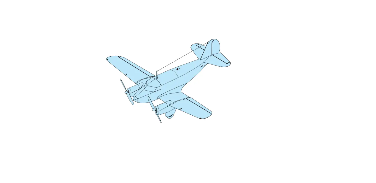
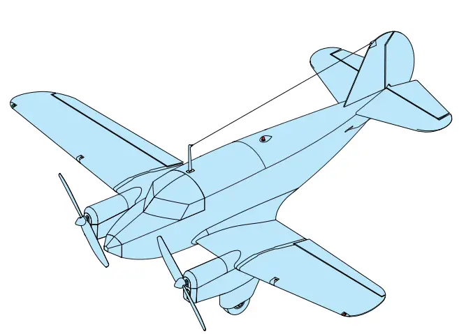
Microaces Percee Debonair Twin Engine Kit
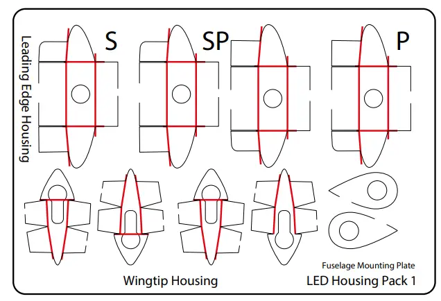
LED HOUSING PARTS 
LENSE PARTS
CLEAR PARTS
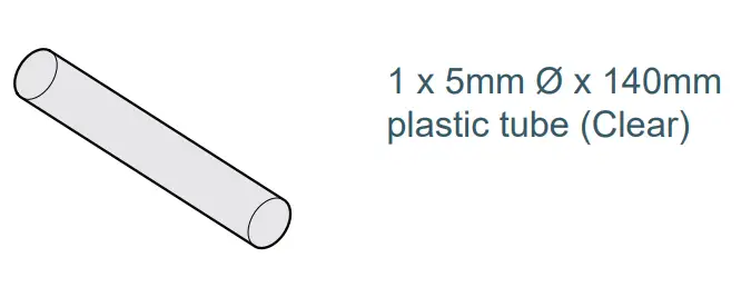
LOOSE PARTS
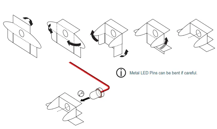
STAGE 1 ANTI-COLLISION LIGHT

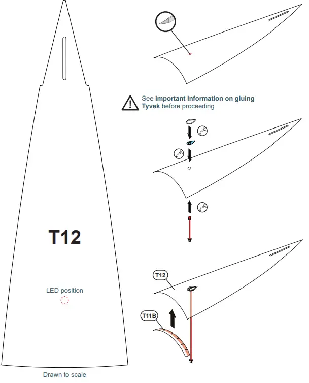
- From page 31 of main Assembly Guide
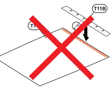
- Do NOT attack T11 until Stage 8 in this guide
- From page 32 of main
STAGE 1 ANTI COLLISION LIGHT
- Return to page 33 of main Assembly Guide
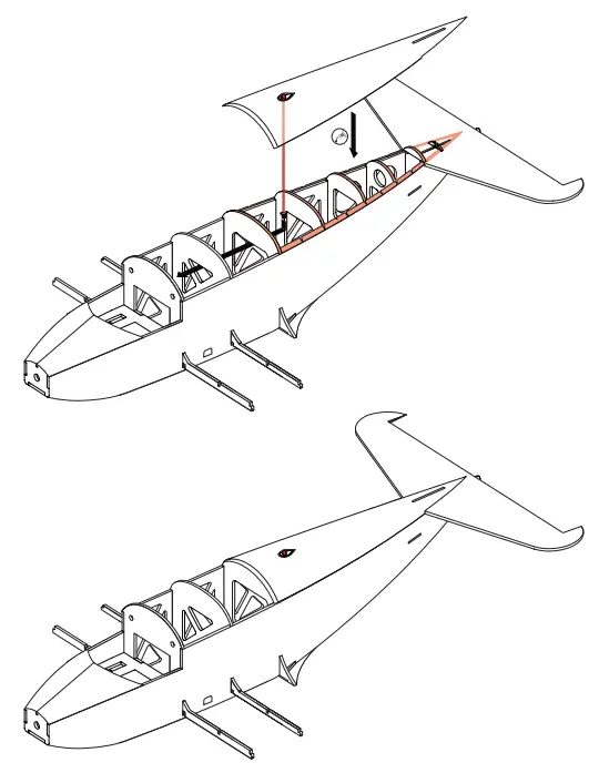
STAGE 2 CABLE INSTALLATION
- From page 33 of main Assembly Guide

- Run motor extension cables OUTSIDE of the plastic tube. Run servo ‘Y’ cable INSIDE plastic tubes.
- Return to page 34 of main Assembly Guide

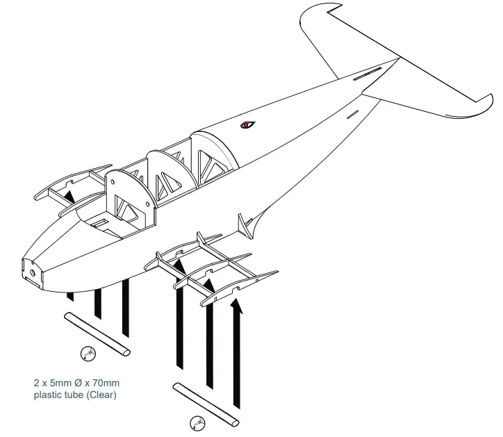
- From page 43 of main Assembly Guide
- Wingtip Housing
- Starboard side illustrated

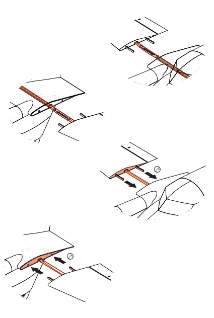
STAGE 4 LANDING LIGHTS
- Leading Edge Housing
- Starboard side illustrated
- Repeat Leading Edge housing assembly for PORT SIDE. (Use plastic housing part labeled ‘P’)
STAGE 5 WINGS + LEDS
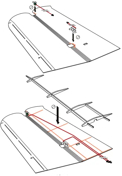
- Starboard side illustrated
- Repeat wing build for PORT SIDE.
- Return to page 44 of main Assembly Guide
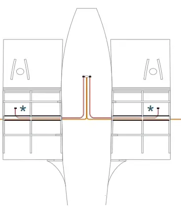
STAGE 6 WINGS
- From page 44 of main Assembly Guide
- Route both LED connectors through a plastic tube into the fuselage interior during the installation of the wing
- Servo connector
- Servo connector
- Return to page 45 of main Assembly Guide
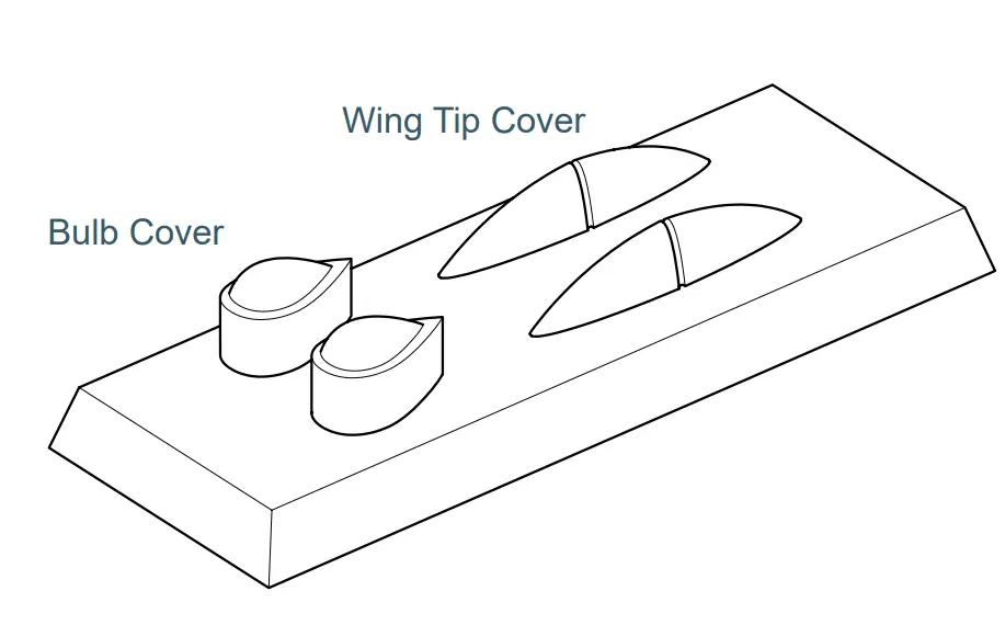
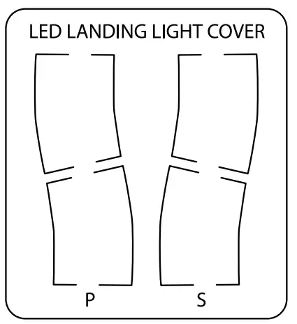
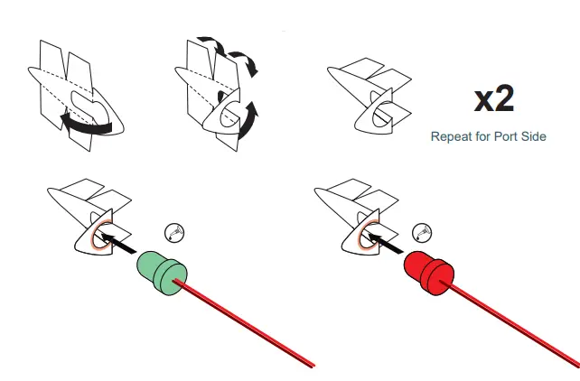
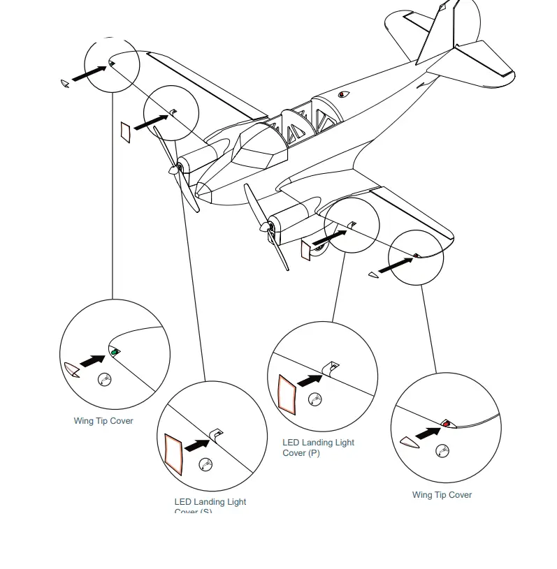
STAGE 7 LED LIGHT COVERS
- From page 51 of the main assembly Guide

STAGE 7 LED CONNECTIONS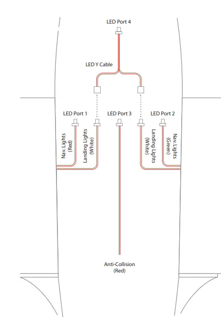
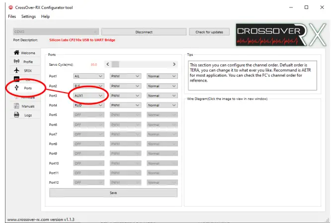
RECEIVER SETUP
- Receiver Setup for LED operation from Transmitter Switch.
- Using the Crossover RX Configuration Tool for PC and the USB Programming Interface Module (UPIM), connect the
- Percee Twin ESC Receiver to your computer and connect. (Refer to the Receiver Guide for detailed instructions)
- From the menu in the Crossover RX app, select the ‘Ports’ tab. Using the drop-down menu, change Port3 from its default (THR) to AUX1. See the image below.
- Click save within the Crossover RX app and disconnect before physically unplugging the receiver from the PC.

- Connecting LCU to Twin ESC Receiver
- Plug the 3 pin JST-SH connector on the LED Control Unit to the THR port on the Twin ESC Receiver.
- The LCU can then be placed in the fuselage, behind the bulkhead. It should not need to be secured in place.
- Setting up your transmitter to operate the LEDs.
- Within your transmitter setting, allocate AUX1 to a 3-way switch on your transmitter. Refer to your transmitter guide for assistance.
- To switch between LED modes, change the position of the switch accordingly.
- For assistance and inquiries contact: [email protected]
STAGE 8 HATCH INSTALLATION
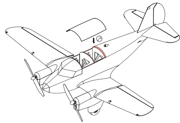
- Return to page 51 of main Assembly Guide


