![]()
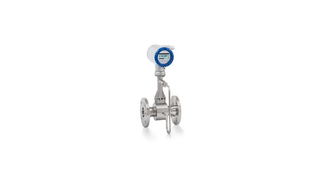
Smart Line®
Versa Flow Vortex 200
VM21 Size 1/2″ to 4″ Sandwich Design
Model Selection Guide 36-VM-16-04
Issue 4
Section: 14
Effective Date: October 1, 2021
Model Selection Guide
Honeywell Proprietary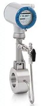 List Price equals the sum of prices for all selections
36-VM-16-04 VersaFlow Vortex 200 Vortex Shedding Flow Meter
- Secondary pressure containment around sensor
- Easily drained and easy to clean
- Regardless of type of installation and external factors
- Excellent zero stability
- Low energy consumption, low operating and installation costs
- Rapid signal processing even with product and temperature changes and sudden changes in density
- Modular electronics concept: electronics and sensor easy to replace
- Data redundancy: accurate plug & play replacement of electronics
Instructions
Select the desired key number. The arrow to the right marks the selection available. Make the desired selections from Tables I through VIII using the column below the proper arrow. An Asterisk ( * ) denotes availability.

| KEY NUMBER | Description | Selection | Availability | |
| VM21 | VM21 | ↓ | ||
| TABLE I | ||||
| Instrument Code | 4F | * | ||
| TABLE II | ||||
| General Information | ||||
| Sensor Material | 316LSS | 1 | * | |
| TABLE III | ||||
| a. Flange Connection size | DN 15 DN 25 DN 40 DN 50 DN 80 DN 100 | / 1/2″ / 1″ / 1 1/2″ / 2″ / 3″ / 4″ | 2 _ _ _ 4 _ _ _ 6 _ _ _ 7 _ _ _ A _ _ _ B _ _ _ | a b c d e f |
| b. Pressure Class | PN 10 PN 16 PN 25 PN 40 PN 63 PN 100 ASME ASME ASME | EN 1092-1 EN 1092-1 EN 1092-1 EN 1092-1 EN 1092-1 EN 1092-1 150 lb 300 lb 600 lb | _ 2 _ _ _ 3 _ _ _ 4 _ _ _ 5 _ _ _ 6 _ _ _ 7 _ _ _ A _ _ _ B _ _ _ D _ _ | * * * * * * * * * |
| c. Flange faces | Sandwich | _ _ 0 _ | * | |
| d. Sensor Size | DN 15 / 1/2″ DN 15 / 1/2″ DN 25 / 1″ DN 25 / 1″ DN 8040 / 1 1/2″ DN 10050 / 2″ DN 15080 / 3″ DN 200100 / 4″ | C Conical Pick-up C Conical Pick-up | _ _ _ 2 _ _ _ 3 _ _ _ 4 _ _ _ 5 _ _ _ 6 _ _ _ 7 _ _ _ A _ _ _ B | * * * * * * * * |
| TABLE IV | ||||
| a. Pressure sensor options | None pressure sensor max. 1 bar pressure sensor max. 2 bar pressure sensor max. 4 bar pressure sensor max. 6 bar pressure sensor max. 10 bar pressure sensor max. 16 bar pressure sensor max. 25 bar pressure sensor max. 40 bar pressure sensor max. 60 bar pressure sensor max. 100 bar pressure sensor max. 1 bar pressure sensor max. 2 bar pressure sensor max. 4 bar pressure sensor max. 6 bar pressure sensor max. 10 bar pressure sensor max. 16 bar pressure sensor max. 25 bar pressure sensor max. 40 bar pressure sensor max. 60 bar pressure sensor max. 100 bar | with isolation valve with isolation valve with isolation valve with isolation valve with isolation valve with isolation valve with isolation valve with isolation valve with isolation valve with isolation valve Be certain to select pressure sensor in accordance with pressure requirements on customer’s application data sheet | 0 _ _ _ 1 _ _ _ 2 _ _ _ 3_ _ _ 4 _ _ _ 5 _ _ _ 6 _ _ _ 7 _ _ _ 8 _ _ _ A _ _ _ B _ _ _ C _ _ _ D _ _ _ E _ _ _ F _ _ _ G _ _ _ H _ _ _ K _ _ _ L _ _ _ M _ _ _ N _ _ _ | * * * * * * * * * * * * * * * * * * * * * |
| b. Gasket material pressure sensor | None FPM FFKM | _ 0 _ _ _ 1 _ _ _ 2 _ _ | * * * | |
| c. Approval | None ATEX II2 G – Ex ia ATEX II2 G – Ex d ATEX II3 G – Ex nA ATEX II2 D – Ex tb IECEx II2 G – Ex ia IECEx II2 G – Ex d IECEx II3 G – Ex nA IECEx II2 D – Ex tb QPS XP Class I US/C AEx d QPS IS Class I US/C AEx i QPS NI Class I US/C AEx nA QPS DIP Class II US/C AEx tb QPS non-Ex (Ordinary Loc.) US and CAN | _ _ 0 _ _ _ 1 _ _ _ 2 _ _ _ 3 _ _ _4_ _ _5 _ _ _ 6 _ _ _ 7 _ _ _ 8 _ _ _ A _ _ _ B _ _ _ C _ _ _D_ _ _ E _ | * * * * * * * * * * * * * * | |
| d. Converter housing | Standard aluminum Aluminum, silicone free (Non Ex and Exi only) Aluminum with weather protection cover (Compact Version) | _ _ _1 _ _ _4 _ _ _ 7 | * i o | |
| TABLE V | ||||
| a. System design and Cable length | Compact without cable 5 m / 16 ft. 10 m / 32 ft. 15 m / 49 ft. 20 m / 65 ft. 25 m / 82 ft. 30 m / 98 ft. 35 m / 114 ft. 40 m / 131 ft. 45 m / 147 ft. 50 m / 164 ft. 5 m / 16 ft. 10 m / 32 ft. 15 m / 49 ft. 20 m / 65 ft. 25 m / 82 ft. 30 m / 98 ft. 35 m / 114 ft. 40 m / 131 ft. 45 m / 147 ft. 50 m / 164 ft. | UV-Resistant UV-Resistant UV-Resistant UV-Resistant UV-Resistant UV-Resistant UV-Resistant UV-Resistant UV-Resistant UV-Resistant | 0 _ _ _ 1 _ _ _ 2 _ _ _ 3 _ _ _ 4 _ _ _ 5 _ _ _ 6 _ _ _ 7 _ _ _ 8 _ _ _ A _ _ _ B _ _ _ E _ _ _ F _ _ _ G _ _ _ H _ _ _ K _ _ _ L _ _ _ M _ _ _ N _ _ _ P _ _ _ R _ _ _ | * * * * * * * * * * * * * * * * * * * * * |
| b. Display | With | _1 _ _ | * | |
| c. Cable connection | without 1pc. M20 x 1,5 grey 2pc. M20 x 1,5 grey 3pc. M20 x 1,5 grey 1pc. M20 x 1,5 blue 2pc. M20 x 1,5 blue 3pc. M20 x 1,5 blue 1 Stk. M20x1,5 brass Ex-d/t/nA 2 Stk. M20x1,5 brass Ex-d/t/nA 3 Stk. M20x1,5 brass Ex-d/t/nA 1pc. M20 x 1,5 s.s. Ex-d/t 2pc. M20 x 1,5 s.s. Ex-d/t 3pc. M20 x 1,5 s.s. Ex-d/t 1pc. 1/2″ NPT 2pc. 1/2″ NPT 3pc. 1/2″ NPT 1pc. G 1/2 2pc. G 1/2 3pc. G 1/2 | _ _ 0 _ _ _ 1 _ _ _ 2 _ _ _ 3 _ _ _ 4 _ _ _ 5 _ _ _ 6 _ _ _ 7 _ _ _8 _ _ _A _ _ _E _ _ _ F _ _ _ G _ _ _ H _ _ _ K _ _ _ L _ _ _M _ _ _ N _ _ _ P _ | * * * * * * * * * * * * * * * * * * * | |
| d. Software version | Standard + steam + gross/net heat for saturated steam and superheated steam Standard; uncompensated for gases, steam and liquids + saturated steam compensation Standard + gross/net heat for saturated steam and water Standard + steam + gross/net heat for saturated and superheated steam + gases + FAD | _ _ _ 0 _ _ _ 1 _ _ _ 2 _ _ _ 3 | m m n n | |
| TABLE VI | ||||
| a. Programming language | English German French Italian Turkish Spanish Slovenian Czech Danish Polish Swedish Chinese Russian | 1 _ _ 2 _ _ 3 _ _ 4 _ _ 5 _ _ 6 _ _ A _ _ B _ _ H_ _ K _ _ M _ _ T _ _ U _ _ | * * * * * * * * * * * * * | |
| b. Communication | HART (Pactware Communication) | _ 0 _ | * | |
| c. Identification | None stainless steel tag 40 x 20 mm stainless steel tag 120 x 46 mm cardboard 90 x 45 mm stainless steel tag 40 x 20 mm + cardboard stainless steel tag 120 x 46 mm + cardboard | _ _ 0 _ _ 1 _ _ 2 _ _ 3 _ _ 4 _ _ 5 | * * * * * * | |
| TABLE VII | ||||
| a. General confirmation | None Certificate of compliance 2.1 acc. EN 10204 | 0 _ _ 1 _ _ | * * | |
| b. Calibration | 3 point calibration certificate 5 point calibration certificate | _ 0 _ _ 1_ | * * | |
| c. Pressure test | None Pressure test + inspection certificate 3.1 | _ _ 0 _ _ 1 | * * | |
| TABLE VIII | ||||
| a. Material test / Certificates | None list of material certificates of pressure bearing metal parts with copies of 3.1 material certificates Material according to NACE MR 0175/ ISO 15156 PMI of pressure bearing metal parts + 3.1 certificate list of material certificates of pressure bearing metal parts with copies of 3.1 material certificates + PMI | 0 _ _ _ _ 1 _ _ _ _ 4 _ _ _ _ 7 _ _ _ _ B _ _ _ _ | * * * * * | |
| b. Hardness test | None Hardness test of pressure bearing parts +3.1 certificate | _ 0 _ _ _ _ 1_ _ _ | * * | |
| c. Cleaning | None Final clean. “Standard” + 2.1 CoC Final clean. “Standard” + 3.1 insp. Cert. F.clean. f. oxygen services + 2.1 CoC F. clean. f. oxygen services + 3.1 insp. Cert. | _ _ 0 _ _ _ _ K _ _ _ _ L _ _ _ _ N _ _ _ _ P _ _ | * * * * * | |
| d. X-ray and dye penetration test | None X-ray on pressurized weldings Dye penetration test on pressurized weldings | _ _ _ 0 _ _ _ _ 4 _ _ _ _ 5 _ | * * * | |
| e. Manual | German English French | _ _ _ _ 1 _ _ _ _ 2 _ _ _ _ 4 | * * * | |
Certificates
General arrangement drawing (Contact Honeywell for price and availability)
Inspection & test plan ITP (Contact Honeywell for price and availability)
Welding procedure, welding plan, welder qualification (Contact Honeywell for price and availability)
X-ray test of pressure bearing weldings (See Table VIII)
Dye penetration test of pressure bearing weldings (See Table VIII)
Stress Calculation (Contact Honeywell for price and availability)
RESTRICTIONS
| Restriction Letter | Available only with | Not Available with | ||
| Table | Selection | Table | Selection | |
| a | IIId | _ _ _ 2 , _ _ _ 3 | ||
| b | IIId | _ _ _ 7 | ||
| c | IIId | _ _ _ 4 , _ _ _ 5 | ||
| d | IIId | _ _ _ 6 | ||
| e | IIId | _ _ _ A | ||
| f | IIId | _ _ _ B | ||
| m | IVa | 0 _ _ _ | ||
| n | IVa | 0 _ _ _ | ||
| i | IVc | _ _ 0 _, _ _ 1 _, _ _ 5 _, _ _ A _, _ _ E _ | ||
| o | Va | 0 _ _ _ | ||
The minimum value of orders acceptable for Honeywell is USD 500. Handling fee is the amount of the difference between USD 500 and the actual purchase price.
Honeywell Process Solutions, 2101 CityWest Blvd., Houston, TX 77042
Printed in U.S.A. © Copyright 2021. Honeywell International Inc.


