autometic Safety Beam Kits Instruction Manual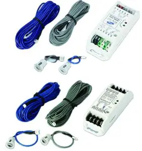
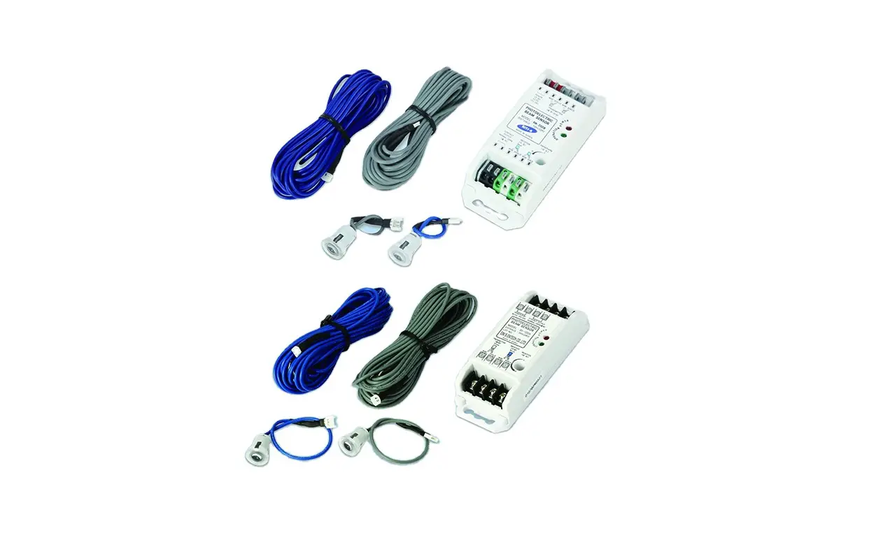
Wireless WPE-2v1
| WPE-2V1 KIT – SAP# ORDER NO. 86802 | ||
| ITEM | DESCRIPTION | QTY |
| 1 | WPB-04.02 TX ASSEMBLY | 1 |
| 2 | WPB-04.02 RX ASSEMBLY | 1 |
| 3 | BASE STATION WPE2V1 ASSEMBLY | 1 |
| 4 | MOUNTING KIT | 1 |
| FLUSH MOUNTING KIT – | ||
| 5 | PEB4-W1 BRACKET | 2 |
| 6 | TAPTITE SCREW “P” M3 X 8 | 8 |
| 7 | SELF TAPPING SCREW M6 X 25 | 4 |
| 8 | PLASTIC WALL PLUG 6.7 X 25 | 4 |
| 9 | TAPTITE SCREW “P” BLACK ZINC M3 X 12 | 8 |
![]() WARNING! When using PE Beams, the doorway must be clear of all obstructions and persons at all times. The location of the beams and manner in which it is installed might no give safety protection at all times. Check to make sure that the height of the beam and type used give maximum protection possible.
WARNING! When using PE Beams, the doorway must be clear of all obstructions and persons at all times. The location of the beams and manner in which it is installed might no give safety protection at all times. Check to make sure that the height of the beam and type used give maximum protection possible.
![]() WARNING! PE beams must be installed if the closing force at the bottom edge of the door exceeds 400N (40kg force)
WARNING! PE beams must be installed if the closing force at the bottom edge of the door exceeds 400N (40kg force)
EasyBeamTM PE-3v1
| EASYBEAM P.E.-3V1 KIT SAP# ORDER NO. 62626 | ||
| ITEM | DESCRIPTION | QTY |
| 14 | EASYBEAM RX-TX SET | 1 |
| 4 | MOUNTING KIT | 1
|
- Right side bracket

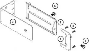
| MOUNTING KIT | ||
ITEM | DESCRIPTION | QTY |
1 | PE 2000TS BRACKET | 2 |
2 | ADJUSTMENT BRACKET | 2 |
3 | MOUNTING BRACKET | 2 |
4 | TAPTITE SCREW “B” PH M3 X 5 ZNC | 8 |
5 | PAN HEAD SCREW W/WASHER M5 X 10 | 4 |
Important Safety Instructions
- When using Safety beams, the doorway must be clear of all obstructions and persons a all times. The location of the beams and manner in which they are installed might not give safety protection at all times.
- The sensors need to be 100mm above the floor level, however, the exact position must be chosen in such a manner that it suits the application, the environmental conditions and provides maximum safety protection.
- When using auto close mode, a Safety beam must be fitted correctly and tested for operation at regular intervals. Extreme caution is recommended when using auto close mode. All safety rules must be followed.
ELECTROCUTION!
Disconnect the power cord from mains power and battery backup (if installed) before making any repairs or removing covers on openers.
CAUTION:
- Ensure ladder is the correct type for job.
- Ensure ladder is on flat ground.
- Ensure user has 3 points of contact while on ladder.
- Ensure the garage door is in good working order by undertaking regular servicing.
- Safety beams must be installed if the closing force at the bottom edge of the door exceeds 400N (40kg)
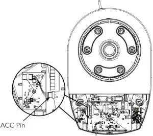
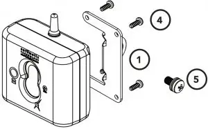
Mounting the Base Station to the Opener
- Disconnect the power supply to the opener.
- Remove the light diffuser cover via screw at the bottom.
- Mount the base station board next to the control board as shown using the screw supplied.
- Plug the harness into the 4 pin connector on the base station board and connect the harness to the ACC pin on the control board.
- Refit the light diffuser.

Inserting batteries into receiver and transmitter
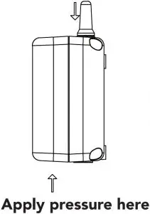
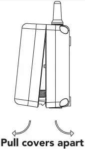
- Insert two (2) C-Type batteries in the Receiver (WPB-4.02 RX) by removing the front cover
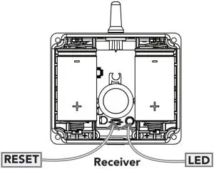
- The LED on the receiver will light up and after the communication is established between the receiver and base station the LED on the base station and the receiver will turn off. This can take up to 60secs.
- Repeat step (a) to insert batteries into the Transmitter (WPB-4.02 TX).
- The LED on the transmitter will light up and after communication is established between the transmitter and base station the LED on the transmitter and on the receiver will start to flash.
- The flashing indicates the link is established between the transmitter and base station, receiver and base station, but receiver and transmitter are not yet alligned.
- Put cover back on Transmitter and Receiver and secure with eight (8) M3 x 12 tap tite screws (black) (9) .


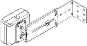
Assembling the Mounting Bracket
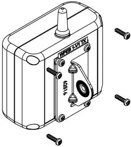
- Attach the PE 2000TS Bracket 1 to the Receiver (WPB-4.02 RX) using four (4) M3 x 5 Taptite screws 4 .
- Connect the mounting bracket 3 to the adjustment bracket 2 with two (2) of the M5 x 10 Pan Head Screws 5 .
- Repeat steps (a) and (b) to assemble the Safety Beam Transmitter (WPB-4.02TX).
- Mount the receiver on the side of the doorway closest to the opener and the transmitter on the other side in line with the receiver. The mounting surface should be rigid. Affix with a minimum of four (4) screws(not supplied).
- ATA recommends the transmitter and receiver are placed in line of sight, with the beam 100mm above the ground level (as per AS60335). This can be achieved by ensuring the bottom of the receiver and transmitter are 65mm above ground level. They should also be placed as close as possible to the door opening.


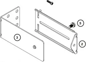
Assemble Flush Mounting Kit (for minimum sideroom applications)
For applications which have limited space available or certain environmental factors a flush mounting kit can be used.
- Attached the transmitter (WPB-4.02TX) and receiver (WPB-4.02RX) to the
two (2) PEB4-W1 Bracket 5 with the eight (8) M3 x 8 Taptite screws “P” 6 . - Ensure to take note of the ATA recommendation in step (e) above and fix the TX and RX to the wall or rigid surface using the two (2) 6.9 x 25 plastic wall plugs 8 (if wall) and two (2) M6 x 25 self tapping screws 7 .

Aligning the Transmitter and Receiver
- Make horizontal and/or vertical adjustment on the transmitter until the red LED on the receiver stays on, this indicates alignment.
- Make horizontal and/or vertical adjustment on the receiver until the red LED on the transmitter stays on, this indicates alignment.
NOTE: Mount the receiver on the side of the doorway / gateway closest to the opener / console.
Assembling the Mounting Bracket
Assemble the mounting bracket as per font page instructions.
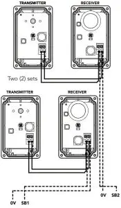
NOTE: When using two (2) sets of Safety Beams within the opening you must alternative the configuration. See diagram.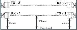
ATA recommends the transmitter and receiver are placed in line of sight, with the beam 100mm above the ground level (as per AS60335). This can be achieved by ensuring the bottom of the receiver and transmitter are 65mm above ground level. They should also be placed as close as possible to the door / gate opening.In industrial applications it is recommended that multiple Safety Beams are fitted.
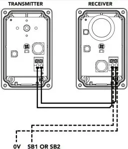
Wiring the EasyBeamTM PE-3v1
- Connect the EasyBeamTM to the opener / console as per the first wiring diagram for one (1) set of safety beams or second wiring diagram for two (2) sets of safety beams.
- One (1) set

- Two (2) sets

![]() WARNING! When using PE Beams, the doorway must be clear of all obstructions and persons at all times. The location of the beams and manner in which it is installed might not give safety protection at all times. Check to make sure that the height of the beam and type used give maximum protection possible.
WARNING! When using PE Beams, the doorway must be clear of all obstructions and persons at all times. The location of the beams and manner in which it is installed might not give safety protection at all times. Check to make sure that the height of the beam and type used give maximum protection possible.
Aligning the Transmitter and Receiver
- Power up the opener with the safety beams connected. The green LED on the transmitter should turn ON to indicate power is present.
- If the receiver is connected to power and the red LED is flashing while the green LED on the transmitter is on, the transmitter and receiver are not aligned.
- Make horizontal and/or vertical adjustment on the transmitter and/or receiver until the red LED on the receiver turns on, indicating.
Setting the limits
After aligning the safety beams, refer to the openers manual to set the travel limits. If Opener already installed, install the safety beams then run the door for 2 cycles for the opener to update details.
Troubleshooting
Symptom | Possible cause | Remedy |
| Base station and receiver LED’s constantly on | Receiver is not coded into base station | Code the receiver into base station |
| Receiver LED constantly on but cannot close the door | Receiver not coded into base station Mains power is not switched on to the opener | Code the receiver into base station. Switch on mains power |
| Receiver LED is blinking and can not close the door | Receiver and transmitters not aligned properly Beam is obstructed | Realign receiver and the transmitter
Remove obstruction from the path of the beam. |
| During optical alignment transmitter LED stopped working | Setup timed out | Press reset button on the transmitter. |
| During optical alignment receiver LED stopped working | Setup timed out | Press reset button on the base station. |
| Wireless PE beam works ok but LED’s on receiver and transmitter stopped working | To save battery power LED on transmitter turns off after number of cycles | No remedy required. |
| LED on the receiver/transmitter started to flash during operation of the door | The battery in the receiver/transmitter is getting flat | Replace the batteries. |
Specifications
Technical Specifications | EasyBeamTM | Wireless |
Infrared beam range | 20m | 6m |
RF link range | – | 10m |
RF link frequency | – | 2.4 Ghz ISM Band |
Batteries for Wireless RX and TX | – | C-Type x 2 |
Battery Life | – | 3 years approx. |
Maintenance
To ensure a long and trouble free life for your Safety Beams, the following is recommended:
- Periodically test the Safety Beam is operating efficiently by obstructing either the transmitter or receiver during the openers operation to ensure the door stops.
- If the Safety Beams are located in a very dusty / dirty environment make sure to clean transmitter and receiver lenses for optimal performance.
- Replace batteries in transmitter or receiver (Wireless WPE-2V1 only) when they start to flash during operation of the door.
Warranty
| WPE-2V1 & PE-3V1 | ||
| ACCESSORIES | 1 year | This warranty is to be read in conjunction with the owner’s copy of the opener installation instruction. |


