![]() ATSAMC21MOTOR Smart ARM-Based Microcontrollers
ATSAMC21MOTOR Smart ARM-Based Microcontrollers
User Guide
ATSAMC21MOTOR Smart ARM-Based Microcontrollers
SMART ARM-based Microcontrollers
ATSAMC21MOTOR
USER GUIDE
ATSAMC21 Microcontroller Card for Atmel Motor Control Starter Kit
The ATSAMC21J18A is an MCU card for Atmel® Motor control starter kits. The hardware has the Atmel SMART ARM® -based MCU, ATSAMC21J18A, with integrated on-board debug support. The MCU card can be directly used with the ATSAMBLDCHV-STK® high voltage motor control kit and the currently available ATSAMD21BLDC24V-STK, a low voltage BLDC, PMSM motor control starter kit. The kit contains a driver board hardware with half-bridge power MOSFET drivers, current and voltage sensing circuit, Hall, and Encoder interface, fault protection circuits, etc. Supported by the Atmel studio integrated development platform, the kit provides easy access to the features of ATSAMC21J18A MCU and explains how to integrate the device in a custom motor control application. Plug-able MCU cards are vailable from Atmel, supporting other SMART ARM MCUs.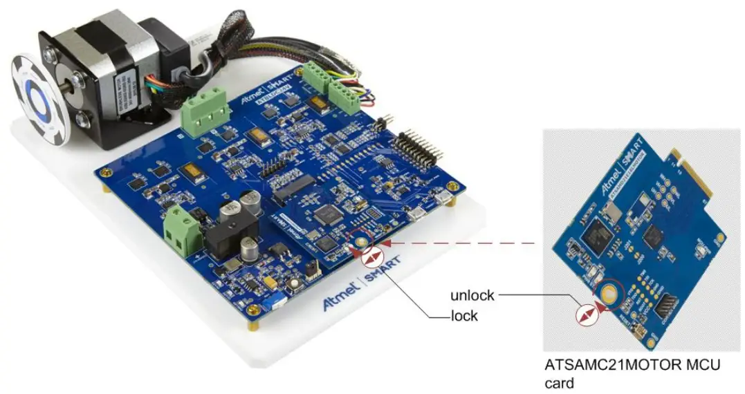
ATSAMC21MOTOR Features
ATSAMC21MOTOR has the following features:
The same port pins are multiplexed between multiple functionalities. PFC, CAN, QTouch® , etc. interfaces are supported only in ATSAMBLDCHV-STK hardware as indicated below.
- Debug support using on-board Atmel EDBG device
- TCC PWM signals for three-phase half-bridge drive
- ADC channels for common shunt and individual shunt phase current sensing
- ADC channels for motor BEMF sensing
- TCC PWM signals for PFC hardware drive (High Voltage kit)
- ADC channels for PFC current sensing (High Voltage kit)
- AC channels for BEMF signals (Low Voltage kit)
- EXTINT hall sensor interface
- EXTINT encoder sensor interface
- PTC QTouch Interface signals (High Voltage kit)
- CAN interface (High Voltage kit)
- Atmel Xplained PRO extension signals support (Low Voltage kit)
- Communication and Power status LEDs
ATSAMC21MOTOR Kit Content
ATSAMC21MOTOR Kit contains an ATSAMC21J18A MCU card that is pre-programmed with hall sensor based block commutation firmware for the ATSAMD21BLDC24V-STK setup. A quick start guide can be found in the ATSAMBLDC24V-STK User quide for Atmel Low voltage BLDC motor control kit. A nylon snap lock is attached to the MCU card that can be rotated to attach the card to the Driver base board in ATSAMD21BLDC24V-STK.
Figure 3-1. ATSAMC21MOTOR Kit Content
Design Documentation and Relevant Links
The following list contains links to the most relevant documents and software for ATSAMC21MOTOR:
- ATSAMC21MOTOR – Product page.
- ATSAMC21MOTOR User Guide – PDF version of this User Guide.
- ATSAMD21BLDC24V-STK – Product page.
- ATSAMBLDC24V-STK User guide – User guide for Atmel Low voltage BLDC motor control kit. It contains the quick start guide instructions and driver board descriptions.
- ATSAMD21BLDC24V-STK Design Documentation – Package containing schematics, BOM, assembly drawings, 3D plots, layer plots, etc.
- Atmel Studio – Free Atmel IDE for development of C/C++ and assembler code for Atmel microcontrollers.
- EDBG User Guide – User guide containing more information about the on-board Embedded Debugger.
- Atmel Data Visualizer – Atmel Data Visualizer is a program used for processing and visualizing data. Data Visualizer can receive data from various sources such as the Embedded Debugger Data Gateway Interface found on Xplained Pro boards and COM ports.
- Xplained Pro products – Atmel Xplained Pro is a series of small-sized and easy-to-use evaluation kits for Atmel microcontrollers and other Atmel products. It consists of a series of low-cost MCU boards for evaluation and demonstration of features and capabilities of different MCU families.
- ATSAMC21MOTOR – MCU datasheet.
ATSAMC21J18A MCU Board
The main components on the ATSAMC21MOTOR MCU card are highlighted in the PCB and in the block diagram given below.
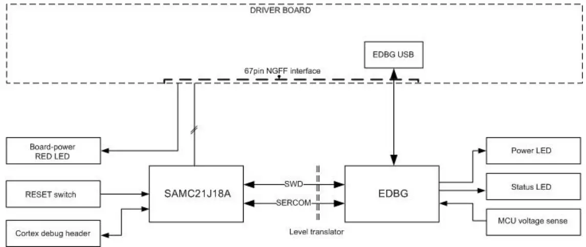
Figure 5-1. MCU Board PCB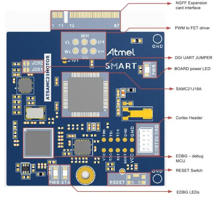 Figure 5-2. MCU Board Block Diagram
5.1. Power Supply
The ATSAMC21J18A MCU takes 5VDC supply from the 67-pin edge connector. The EDBG debug MCU operates on a 3.3VDC supply from the same edge connector. The power supply selection jumper on the Driver board (ATSAMBLDCHV-STK and ATSAMBLDC24V-STK) should be connected to 5V (silk screen text) selection.
5.2. Main MCU Circuit
The ATSAMC21MOTOR has an ATSAMC21 device. The device is intended to work with the MCU internal clock source. An external reset switch is connected to the MCU RESET pin.
5.3. Embedded Debugger
The ATSAMC21J18A MCU is interfaced to the EDBG debug device. The EDBG uses SWD interface for programming and debugging the main MCU. A debug header is also provided on the MCU board with ARM Cortex® debug pinout. An external debugger can be connected to this debug port. The DGI is a proprietary communication interface used by the Atmel Data Visualizer software to communicate with the development kits through the EDBG. The SERCOM5 of the ATSAMC21J18A connected to the EDBG device, supports the DGI SPI interface and uses the Atmel ADP protocol. The MCU SERCOM5 is also connected to the UART channel of the EDBG through a pair of “normally open” jumpers; J201 and J202. Shorting these jumpers will enable the CDC UART interface for the main MCU. High Speed USB port of the EDBG is accessible at the driver board. EDBG USB enumerates as a composite device supporting debug, DGI SPI, and CDC interfaces.
5.4. 67-pin MCU-DRIVER Board Interface
MCU pins are connected to the 67-pin interface header as given in the table below. The MCU card can be used with the Motor control driver kits from Atmel. The table given below describes the interface with Atmel low voltage motor control starter kit. Signals indicated by “||” are jumper connected pins that share directly connected functionality. The normally-open jumper needs to be shorted in the PCB in order to access these additional features.
Table 5-1. ATSAMBLDC24V-STK and ATSAMC21J18A MCU Card Interface (67 pin NGFF connector) Description
| PIN LV INTERFACE Name | LV DRIVER BOARD function | SAM C21 PIN | SAM C21 function |
| 1 EDBG USB HSP | EDBG USB | EDBG_USB_HS_P | EDBG_USB_HS_P |
| 2 NC | NC | PA24 | CAN TX |
| 3 EDBG USB HSN | EDBG USB | EDBG_USB_HS_N | EDBG_USB_HS_N |
| 4 EDBG ID2 | EDBG_ID2/EXT1_1 | EDBG PB01 | EDBG ID2 |
| 5 NC | NC | PA25 | CAN RX |
| 6 EDBG ID1 | EDBG_ID1 | EDBG PA28 | EDBG_ID1 |
| 7 MCU USB DP | TARGET_USB_HS_P | NC | NC |
| 8 TARGET USB VBUS | VCC_TARGET_USB_ P5V0 | NC | NC |
| 9 MCU USB DN | TARGET_USB_HS_N | NC | NC |
| 10 EDBG USB VBUS | VCC_EDBG_USB_P5 V0 | VCC_EDBG_USB_P5 V0 | VCC_EDBG_USB_P5 V0 |
| 11 TARGET_USB_ID | TARGET_USB_ID | NC | NC |
| 12 TEMP SDA | TWI_SDA, EXT1_11 | PA22 | SERCOM3(PAD0) |
| 13 TEMP SCL | TWI_SCL, EXT_12 | PA23 | SERCOM3(PAD1) |
| 14 FLASH SS | SPI_SS | PB13 | SERCOM4(PAD1) |
| 15 FLASH MISO | SPI_MISO, EXT1_17 | PB12 | SERCOM4(PAD0) |
| 16 FLASH SCK | SPI_SCK, EXT1_18 | PB15 | SERCOM4(PAD3) |
| 17 FLASH MOSI | SPI_MOSI, EXT1_16 | PB14 | SERCOM4(PAD2) |
| 18 MCU GPIO1 | EXT1_7(GPIO1) | PA19 | PTC(X5) |
| 19 MCU GPIO2 | EXT1_8(GPIO2) | PB03 | TC6(W1) |
| 20 MCU GPIO3 | EXT_3 | PA02 | ADC0(AIN0) |
| 21 MCU GPIO4 | NC(GPIO4) | PB22 | TC7(WO0) |
| 22 MCU GPIO5 | EXT1_5(GPIO5) | PB31 | GPIO |
| 23 MCU GPIO6 | EXT1_6(GPIO6) | PA17 | EXTINT1 |
| 24 MCU GPIO7 | Temp_Alert(GPIO7) | PA27 | EXTINT15 |
| 25 OCP | OCP(GPIO8) | PA03 | ADC0(AIN1) |
| 26 EXT1 RXD | UART RXD_ EXT1_13 | PB17 | SERCOM5(PAD1) |
| 27 EXT1 TXD | UART TXD_EXT1_14 | PB02 | SERCOM5(PAD0) |
| 28 PWM UH | FET Driver | PB30 | TCC0(WO0) |
| 29 PWM UL | FET Driver | PA14 | TCC0(WO4) |
| 30 PWM VH | FET Driver | PA05 | TCC0(WO1) |
| 31 PWM VL | FET Driver | PA15 | TCC0(WO5) |
| 32 PWM WH | FET Driver | PA10 | TCC0(WO2) |
| 33 PWM WL | FET Driver | PA16 | TCC0(WO6) |
| 34 MCU_GPIO8 (ISENSE_COMMON) | EXT_15 | PB05 | ADC1(AIN7) |
| 35 ATA RESET | EXT1_4(GPIO10) | PB16 | GPIO |
| 36 ATA WD | EXT1_10(GPIO11) | PA12 | TCC2(WO0) |
| 37 ATA SLEEP | EXT1_9(GPIO12) | PA13 | TCC2(WO1) |
| 38 USHUNT_ADC | Current sense | PB08 | ADC0(AIN2) |
| 39 VSHUNT_ADC | Current sense | PB09 | ADC0(AIN3) |
| 40 WSHUNT_ADC | Current sense | PA08 | ADC0(AIN8) |
| 41 MOTOR VDC (V SENSE) | MOTOR_ADC | PA09 | ADC0(AIN9) |
| 42 BEMF U_ADC | BEMF sense ADC | PB00 | ADC1(AIN0) |
| 43 BEMF V_ADC | BEMF sense ADC | PB01 | ADC1(AIN1) |
| 44 BEMF_W_ADC | BEMF sense ADC | PB06 | ADC1(AIN8) |
| 45 BEMF UP | BEMD sense AC | PA04 | ADC0(AIN4) |
| 46 BEMF UN | BEMD sense AC | PB07 | ADC1(AIN9) |
| 47 BEMF VP | BEMD sense AC | PA06 | ADC0(AIN6) |
| 48 BEMF VN | BEMD sense AC | NC | NC |
| 49 BEMF WP | BEMD sense AC | PA07 | ADC0(AIN7) |
| 50 BEMF WN | BEMD sense AC | NC | NC |
| 51 HALL1 | Hall interface | PB11 | EXTINT11 |
| 52 HALL2 | Hall interface | PB04 | EXTINT4 |
| 53 HALL3 | Hall interface | PA28 | EXTINT8 |
| 54 HALL TRX OE | HALL_TRX_OE | NC | NC |
| 55 ENCODER_A | Encoder Interface | PA18 | EXTINT2 |
| 56 ENCODER_B | Encoder Interface | PB10 | EXTINT10 |
| 57 ENCODER_Z | Encoder Interface | PB23 | EXTINT7 |
| 58 ENCODER_EN | ENCODER EN | NC | NC |
| 59 NC | NC | VCC_P3V3 | VCC_P3V3 |
| 60 MCU BRAKE | NC | PA11 | TC1(WO1) |
| 61 NC | NC | VCC-P3V3 | VCC_P3V3 |
| 62 3V3 SUPPLY for MCU | VCC_P | VCC_TARGET_P5V0 | VCC_TARGET_P5V0 |
| 63 3V3 SUPPLY for MCU | VCC_P | VCC_TARGET_P5V0 | VCC_TARGET_P5V0 |
| 64 GND | GND | GND | GND |
| 65 GND | GND | GND | GND |
| 66 GND | GND | GND | GND |
| 67 GND | GND | GND | GND |
Product Compliance
RoHS and WEEE
The Atmel ATSAMC21MOTOR and its accessories are manufactured in accordance to both the RoHS Directive (2002/95/EC) and the WEEE Directive (2002/96/EC).
CE and FCC
The Atmel ATSAMC21MOTOR unit has been tested in accordance to the essential requirements and other relevant provisions of Directives:
- Directive 2004/108/EC (class B)
- FCC rules part 15 subpart B
The following standards are used for evaluation:
- EN 61326-1 (2013)
- FCC CFR 47 Part 15 (2013)
The Technical Construction File is located at:
Atmel Norway
Vestre Rosten 79
7075 Tiller
Norway
Every effort has been made to minimize electromagnetic emissions from this product. However, under certain conditions, the system (this product connected to a target application circuit) may emit individual electromagnetic component frequencies which exceed the maximum values allowed by the abovementioned standards. The frequency and magnitude of the emissions will be determined by several factors, including layout and routing of the target application with which the product is used.
Identifying Product ID and Revision
The revision and product identifier of the ATSAMC21MOTOR can be found by looking at the sticker on the bottom side of the PCB. The identifier and revision are printed in plain text as A09-nnnn\rr, where nnnn is the identifier and rr is the revision. Also the label contains a 10-digit unique serial number. The product identifier for ATSAMC21MOTOR is A09-2550.
Revision
Kit assembly revision for initial version is A09-2550/03. Known issues in this revision are:
• PWM silk text for WH and UH are swapped
Document Revision History
Doc. rev……….42747A
Date……………………..09/2016
Comment……………. Initial document release
Atmel ATSAMC21MOTOR [USER GUIDE]
Atmel-42770A-ATSAMC21MOTOR_User Guide-09/2016
2016 Atmel© Corporation. / Rev.: Atmel-42770A-ATSAMC21MOTOR_User Guide-09/2016
Atmel® , Atmel® logo and combinations thereof, Enabling Unlimited Possibilities® , QTouch® , STK® , and others are registered trademarks or trademarks of Atmel Corporation in U.S. and other countries. ARM® , ARM Connected® logo, Cortex® , and others are the registered trademarks or trademarks of ARM Ltd. Other terms and product names may be trademarks of others.
DISCLAIMER: The information in this document is provided in connection with Atmel products. No license, express or implied, by estoppel or otherwise, to any
intellectual property right is granted by this document or in connection with the sale of Atmel products. EXCEPT AS SET FORTH IN THE ATMEL TERMS AND
CONDITIONS OF SALES LOCATED ON THE ATMEL WEBSITE, ATMEL ASSUMES NO LIABILITY WHATSOEVER AND DISCLAIMS ANY EXPRESS, IMPLIED OR STATUTORY WARRANTY RELATING TO ITS PRODUCTS INCLUDING, BUT NOT LIMITED TO, THE IMPLIED WARRANTY OF MERCHANTABILITY, FITNESS FOR A PARTICULAR PURPOSE, OR NON-INFRINGEMENT. IN NO EVENT SHALL ATMEL BE LIABLE FOR ANY DIRECT, INDIRECT, CONSEQUENTIAL, PUNITIVE, SPECIAL OR INCIDENTAL DAMAGES (INCLUDING, WITHOUT LIMITATION, DAMAGES FOR LOSS AND PROFITS, BUSINESS INTERRUPTION, OR LOSS OF INFORMATION) ARISING OUT OF THE USE OR INABILITY TO USE THIS DOCUMENT, EVEN IF ATMEL HAS BEEN ADVISED OF THE POSSIBILITY OF SUCH DAMAGES. Atmel makes no representations or warranties with respect to the accuracy or completeness of the contents of this document and reserves the right to make changes to specifications and products descriptions at any time without notice. Atmel does not make any commitment to update the information contained herein. Unless specifically provided otherwise, Atmel products are not suitable for, and shall not be used in, automotive applications. Atmel products are not intended, authorized, or warranted for use as components in applications intended to support or sustain life.
SAFETY-CRITICAL, MILITARY, AND AUTOMOTIVE APPLICATIONS DISCLAIMER: Atmel products are not designed for and will not be used in connection with any applications where the failure of such products would reasonably be expected to result in significant personal injury or death (“Safety-Critical Applications”) without an Atmel officer’s specific written consent. Safety-Critical Applications include, without limitation, life support devices and systems, equipment or systems for the operation of nuclear facilities and weapons systems. Atmel products are not designed nor intended for use in military or aerospace applications or environments unless specifically designated by Atmel as military-grade. Atmel products are not designed nor intended for use in automotive applications unless specifically designated by Atmel as automotive-grade.
![]() Atmel Corporation
Atmel Corporation
1600 Technology Drive, San Jose, CA 95110 USA
T: (+1)(408) 441.0311
F: (+1)(408) 436.4200
www.atmel.com
Downloaded from Arrow.com.![]()


