![]() HAT310 ATS Controller
HAT310 ATS Controller
User Manual
HAT310 ATS Controller
![]()
SmartGen ―make your generator smart
SmartGen Technology Co., Ltd
No.28 Jinsuo Road, Zhengzhou, Henan Province, China
Tel: +86-371-67988888/67981888/67992951
+86-371-67981000(overseas)
Fax: +86-371-67992952
Web: www.smartgen.com.cn/
www.smartgen.cn/
Email: [email protected]
All rights reserved. No part of this publication may be reproduced in any material form (including photocopying or storing in any medium by electronic means or other) without the written permission of the copyright holder.
Applications for the copyright holder’s written permission to reproduce any part of this publication should be addressed to Smartgen Technology at the address above.
Any reference to trademarked product names used within this publication is owned by their respective companies.
SmartGen Technology reserves the right to change the contents of this document without prior notice.
Table 1 Software Version
| Date | Version | Content |
| 6/21/2017 | 1 | Original release |
| 3/3/2021 | 1.3 | Update the company address, contact information, and manual format; Modify the wiring method of A1、A2、B1, and B2 for the SGQ-N/T switch in Figure 4. |
| 7/25/2022 | 1.4 | Update company logo. |
OVERVIEW
HAT310 ATS Controller is suitable for 2-stage of PC, and ATS of CC class (close signal is constant output). It can accurately detect 3-phase 4-wire mains voltage and generator single phase voltage. When mains under voltage and loss of phase occur, HAT310 will control ATS transfer after delay. The controller can initiate signals to start Genset if mains are unavailable.
PERFORMANCE AND CHARACTERISTICS
HAT310 controller can detect 3-phase 4-wire mains voltage/generator single phase voltage and control ATS.
The main characteristics are as follows,
- With automatic transfer and restore function.
- With under voltage and loss of phase detection function.
- LED indicators on the panel can show the working status of the controller clearly.
- Applicable for 2 isolated neutral lines.
- Mains normal delay configured via a potentiometer (range: 1~60s), and generator normal delay via a potentiometer (range: 1~60s).
- Mains is unavailable, if any phase voltage is below the minimum working voltage or phase loss occurred Genset will be started.
- The output contact capacity of the mains and generator transfer relay is 16A AC250V, which can be directly used to drive switch conversion.
- Output contact capacity of GENS START relay is 16A AC250V, it is volt-free normally open/normally-closed contact.
- Strong anti-electromagnetic interference performance enables the controller to use in an environment with strong electromagnetic interference.
- Modular design, self-extinguishing ABS plastic shell, pluggable terminal, compact structure.
- Two installation ways: internal 35mm guide rail and internal screw mounting.
SPECIFICATION
Table 2 Technical Parameters
| Items | Contents |
| Operating Voltage | AC power Al N1 /A2N2 supply. Rated AC240V (range: AC160-280V) |
| Power Consumption | Under rated voltage, the power consumption of the voltage circuit is not more than 2W |
| AC Voltage Input: 3-phase 4-wire Single-phase 2-wire | AC160V – AC280V (ph-N) AC160V – AC280V (ph-N) |
| AC Frequency | 50/60Hz |
| Gens-set Starter Relay | 16A 250VAC Volts free output (Normally close) |
| Mains Close Relay | 16A 250VAC Active supply output (Normally open) |
| Gen Close Relay | 16A 250VAC Active supply output (Normally open) |
| Case Dimensions | 11 Ommx77.5mmx58mm |
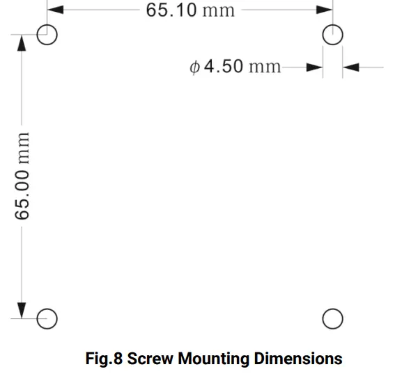
| Screw Mounting Dimensions | 65mmx65.1mm |
| Working Temperature | (-25–+70)°C |
| Working Humidity | (20-93)%RH |
| Storage Temperature | (-25—+70)°C |
| Insulation Strength | Apply AC2.2kV voltage between high voltage terminal and low voltage terminal; The leakage current is not more than 3mA within 1 min. |
| Weight | 0.2kg |
PANEL DESCRIPTION
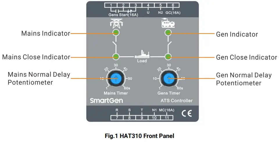
4.1 FRONT PANEL
4.2 POTENTIOMETER FUNCTION DESCRIPTION
Table 3 Potentiometer Function Description
| Potentiometer | Description |
| Mains normal delay potentiometer | Rotate potentiometer knob to adjust mains normal delay value (range: 1-60s), factory default: 5s. |
| Gen normal potentiometer | Rotate potentiometer knob to adjust gen normal delay value (range: 1-60s), factory default: 5s. |
4.3 INDICATOR DESCRIPTION
Table 4 Indicator Description
| Indicators | Description |
| Mains indicator | Light on: mains power available; Light off: mains power unavailable (one phase voltage under 160V or loss of phase). |
| Gen indicator | Light on: generator power available; Light off: generator without power supply. |
| Mains close indicator | Light on: mains provide power for the load. |
| Gen close indicator | Light on: generator provides power for the load. |
4.4 OPERATION
4.4.1 MAINS CLOSE
When mains power is available, its indicator on the panel of the controller is illuminated, and the mains close relay is connected after the delay. Then Genset starter relay coil is powered on and the mains close indicator is illuminated.
4.4.2 GEN CLOSE
When mains power is unavailable or any phase voltage is under 160V or loss of phase, both mains close indicator and mains indicator are off. The mains close relay is disconnected and the engine starter relay coil is power-off. If genset is available at this moment, the gen power indicator is illuminated and the gen close relay is connecting after the delay, and then the gen close indicator is illuminated.
CONNECTION
The controller front panel drawing is as follows,
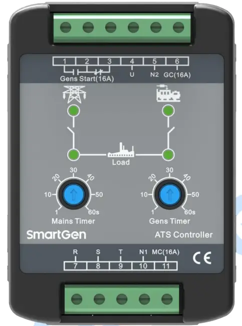
Fig.2 Controller Front Panel
Table 5 Terminal Connection Description
| Terminal | Item | Function | Remark | |
| 1 | Gens Start | NO | Genset start signals output | Volts free normally open (NO)/normally close (NC) output, rated 16A. |
| 2 | COM | |||
| 3 | NC | |||
| 4 | U | Genset AC power supply A phase | Generator AC power supply single phase voltage input. | |
| 5 | N2 | Genset AC power supply N phase | ||
| 6 | GC | Gen close output | When close, it will output U-phase voltage with rated 16A. | |
| 7 | R | Mains AC power supply A-phase | Mains AC power supply 3-phase 4-wire voltage input. | |
| 8 | S | Mains AC power supply B-phase | ||
| 9 | T | Mains AC power supply C-phase | ||
| 10 | N1 | Mains AC power supply N-phase | ||
| 11 | MC | Mains close output | When close, it will output R-phase voltage with rated 16A. | |
![]() NOTE: See Typical Application for more details.
NOTE: See Typical Application for more details.
TYPICAL APPLICATION
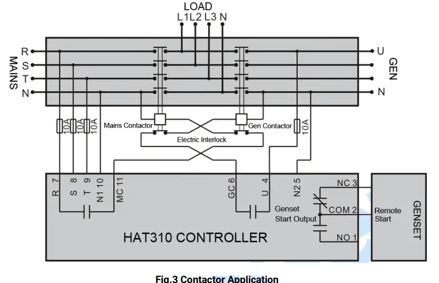
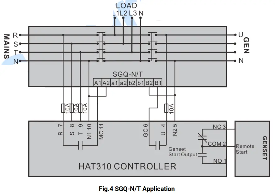
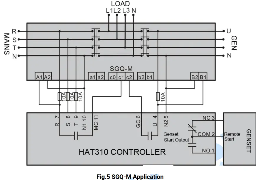
![]() NOTE: Above applications can be referenced when wire connecting. The actual wire connection should according to ATS wiring instructions. Choose fuse capacity based on the local actual power consumption instead of the fuse capacity in the above drawings.
NOTE: Above applications can be referenced when wire connecting. The actual wire connection should according to ATS wiring instructions. Choose fuse capacity based on the local actual power consumption instead of the fuse capacity in the above drawings.
CASE DIMENSION AND PANEL CUTOUT
7.1 CASE DIMENSION
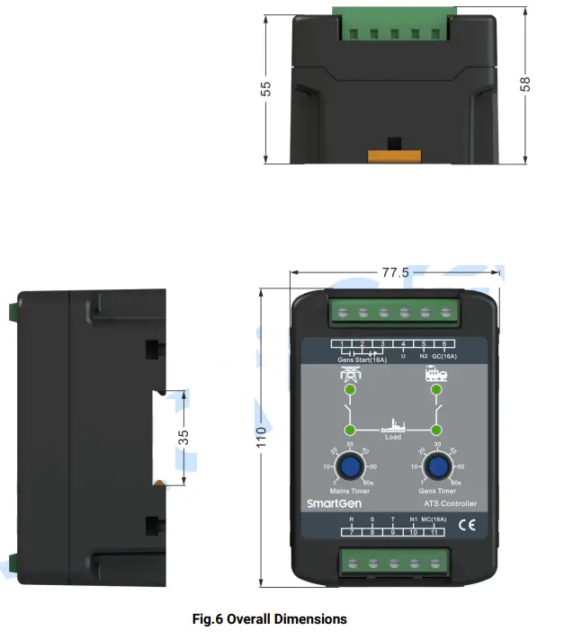
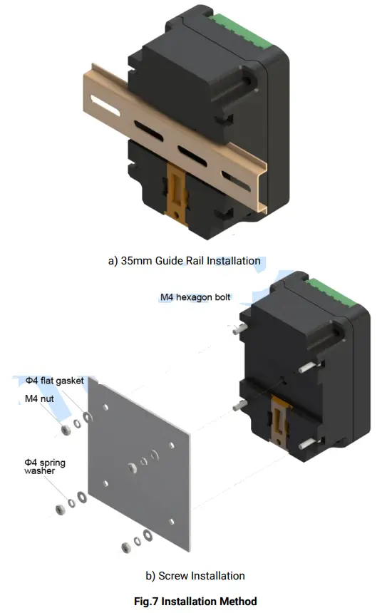
7.2 INSTALLATION METHOD AND INSTALLATION DIMENSIONS
The controller has two installation ways: internal 35mm guide rail and internal screw mounting. Panel built-in and internal screw mounting are as below:
TROUBLESHOOTING
Table 6 Troubleshooting
| Symptom | Possible Remedy |
| Controller not operation | Check mains and generator wire connections and voltage. |
| The controller is normal but ATS is not active | Check ATS; heck the connections between the controller and ATS. |


