FILL-RITE H-Series Fuel Transfer Pumps
Thank You!
Thank you for your loyalty to the Fill-Rite® brand of fuel transfer pumps. Your safety is important, so please read and thoroughly understand the procedures set forth in this manual. In addition, please save these instructions for future reference and record the model, serial number, and purchase date of your fuel transfer pump. Protect yourself as well as those around you by observing all safety instructions and adhering to all danger, warning, and caution symbols. Please register your Fill-Rite® product via info.fillrite.com/product_registration.
IMPORTANT RETURN POLICY
Please do not return this product to the store. For all warranty and product questions, please contact Fill-Rite Technical Support at 1 (800) 720-5192 or via email at [email protected] (M-F, 8 AM – 5 PM ET).
MODEL#
SERIAL#
PURCHASE DATE:
Limited Warranty Policy
Fill-Rite Company warrants the goods manufactured shall be free from defects of materials and workmanship. Specific warranty details for individual products can be found at fillrite.com.
H-Series Fuel Transfer Pumps Have the Following Features
- Adjustable Electrical Junction Box
Rotates 180 degrees to provide ease of electrical wiring installation in tight quarters no matter the inlet bung location - Reliable, Heavy-Duty Power Switch Lever
Features a cast metal stop that withstands heavy use in the most rugged environments - Locking Bar Defense
Elongated bar simplifies the pad locking process to prevent theft - Focused Component Weight Reduction
Preserves expected heavy-duty performance while improving installation ease - Premium Paint Shield
An exemplary corrosion resistant barrier for long field life - Thermally Protected Motor
Prevents overheating to ensure maximum motor life - Telescoping Inlet Metal Suction Pipe*
Adjustable from 20 to 34 inches in length, allowing for universal installation on a multitude of tank sizes and shapes
*Not included with SD models - Intake Strainer Safeguard
Protects the pump by blocking particles created by contamination - Certifications – UL, cUL
About This Manual
From initial concept and design through final production, your Fill-Rite fuel transfer pump is built to provide years of trouble-free use. To ensure the safety of yourself and those around you, it is critical that this manual is read in its entirety prior to attempting to install or operate your new purchase. We strongly urge that any installer and operator become familiar with the terms, diagrams, and technical data in this manual and pay close attention to warning symbols and definitions. At Fill-Rite, your satisfaction with our products is paramount. If you have questions or need assistance with your product, please contact Fill-Rite Technical Support at 1 (800) 720-5192 (M-F, 8am-5pm ET).
Symbols and Definitions
![]() Indicates a hazardous situation which, if not avoided, will result in death or serious injury.
Indicates a hazardous situation which, if not avoided, will result in death or serious injury.
![]() Indicates a hazardous situation which, if not avoided, could result in death or serious injury.
Indicates a hazardous situation which, if not avoided, could result in death or serious injury.
![]() Indicates a hazardous situation which, if not avoided, could result in moderate or minor injury.
Indicates a hazardous situation which, if not avoided, could result in moderate or minor injury.
![]() Indicates information considered important but not directly hazard related.
Indicates information considered important but not directly hazard related.
Before You Begin
Fueling Requirements
The Fill-Rite FR1200, FR2400, FR4200, FR4400, FR600 as well as SD1200 and SD600 models are designed and approved for use with the following flammable and combustible fluids: gasoline and gasoline blends up to 15% or E15, diesel, biodiesel blends up to 20% or B20, kerosene, and mineral spirits.
Please take all necessary precautions when handling flammable liquids.
Power Source Requirements
Depending on the Fill-Rite model, supply line power will either be 12V DC, 24V DC, or 115V AC. The pump motor nameplate located next to the switch lever will provide detailed electrical information. Please refer to the appropriate electrical instructions found starting on Page 7 (DC power) or Page 10 (AC power).
Items that may be needed for installation:
Steel pipe wrench 14-24″, open end wrench or socket (7/16″, 11mm), T-25 Torx driver, utility knife, angle grinder or hacksaw (optional), wire cutters, wire stripper/crimper, and thread sealant (optional).
NOTE: Fill-Rite provides Teflon® tape for all models as listed on Page 16.
Safety Information
To ensure a safe installation and proper equipment operation, please read, understand, and adhere to all DANGER/WARNING/CAUTION and other NOTICES.
![]() Never smoke around or near a fuel tank or transfer pump. Open flames or a spark when pumping a flammable liquid will result in a fire. Improper electrical wiring or installation will result in serious injury or death.
Never smoke around or near a fuel tank or transfer pump. Open flames or a spark when pumping a flammable liquid will result in a fire. Improper electrical wiring or installation will result in serious injury or death.
![]() Electrical wiring should ONLY be performed by a licensed electrician in compliance with all local, state, and national electrical codes (NEC/ANSI/NFPA 30, NFPA 30A, and NFPA 70) as appropriate for the intended use of a Fill-Rite fuel transfer pump.
Electrical wiring should ONLY be performed by a licensed electrician in compliance with all local, state, and national electrical codes (NEC/ANSI/NFPA 30, NFPA 30A, and NFPA 70) as appropriate for the intended use of a Fill-Rite fuel transfer pump.
Threaded rigid conduit, sealed fittings, and conductor seal should be used where applicable and as defined by these codes.
This product must be properly bonded or grounded to avoid the build up of static electricity when handling flammable products. Static discharge may ignite vapors causing serious injury or death.
Fill-Rite pumps are not suited for use with water or fluids intended for human consumption. Do not use to fuel aircrafts.
To minimize static electricity build up, keep the nozzle in contact with the container being filled at all times during the filling process. Use only static wire conductive hose when pumping flammable liquid. Improper mechanical installation or use can result in serious injury or death.
![]() Threaded pipe joints and connections must be sealed with the appropriate sealant or sealant tape to prevent leaks.
Threaded pipe joints and connections must be sealed with the appropriate sealant or sealant tape to prevent leaks.
All Fill-Rite pump models are equipped with thermal overload protection by which the motor will shut off to prevent heat damage. If motor is turned off by a thermal overload, turn the switch lever to the OFF position. Once the motor has cooled sufficiently, turn the switch lever to the ON position to resume fuel transfer.
Some Fill-Rite models will restart automatically if the switch lever is not in the OFF position once the thermal protector resets. As good practice, always place the switch lever in the OFF position when the motor overheats.
![]() A filter should be used on the pump outlet to avoid contamination into the vehicle or equipment’s fuel tank. We recommend Fill-Rite filters for best results.
A filter should be used on the pump outlet to avoid contamination into the vehicle or equipment’s fuel tank. We recommend Fill-Rite filters for best results.
To prevent fuel storage tanks from shifting or tipping, refer to tank manufacturer’s guidelines on proper anchoring.
Installation
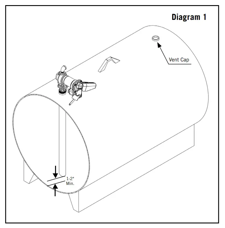
Your Fill-Rite pump is designed to be mounted on a fuel tank via a threaded inlet flange supplied with the pump. Typical installations are shown in Diagram 1 and 2. Your pump features an integral bypass valve to recirculate the fluid when the pump is operating with the nozzle closed.
![]() Do not use additional check valves or foot valves unless they have a proper pressure relief valve built into them.
Do not use additional check valves or foot valves unless they have a proper pressure relief valve built into them.
Please be aware that additional check valves will reduce flow rates.
A pressure-retaining fill cap can be used to reduce fuel loss through evaporation.
Threaded pipe joints and connections must be sealed with the appropriate sealant to prevent leaks.
Use caution to prevent cross-threading during installation which can cause damage to either or both the inlet flange as well as storage tank bung.
![]() In all tank applications, be sure the tank is properly secured per tank manufacturer’s guidelines.
In all tank applications, be sure the tank is properly secured per tank manufacturer’s guidelines.
Stationary Tank
For stationary fuel tanks, the pump mounts to the tank bung by way of the pump inlet flange. Given the different sizes of stationary fuel tanks, a custom suction or inlet pipe may be necessary. We recommend 1” NPT black iron pipe that is extended to a length of at least 1-2” from the bottom of the tank, with the bottom of the pipe cut to an angle between 30-45 degrees for improved flow.
A stationary tank must be equipped with a vent cap. (Diagram 1)
Mobile Tank
For mobile fuel tanks, the pump mounts to the tank bung by way
of the pump inlet flange.
For Telescoping Steel Suction Pipe
Allow telescoping tube to extend fully to the bottom of the tank.
For Custom or PVC Suction Pipe
To avoid penetrating the tank, we recommend leaving a minimum of 1-2” of the pipe off the bottom of tank. We further recommend cutting the suction pipe to a 30-45 degree angle for improved flow.
The mobile tank must be equipped with a vent cap. (Diagram 2)

Installation Procedure
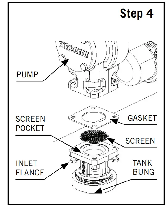
Step 1: (Optional) Inlet Flange Removal Loosen (4) 1/4″ bolts using 7/16″ wrench or socket. Detach inlet bung from pump, retain bolts, screen, and gasket.
Step 2: Using either included suction pipe or custom pipe, thread pipe into inlet bung 1.5 to 2.5 turns past hand tight with pipe wrench. Use appropriate sealant for fuel transfer.
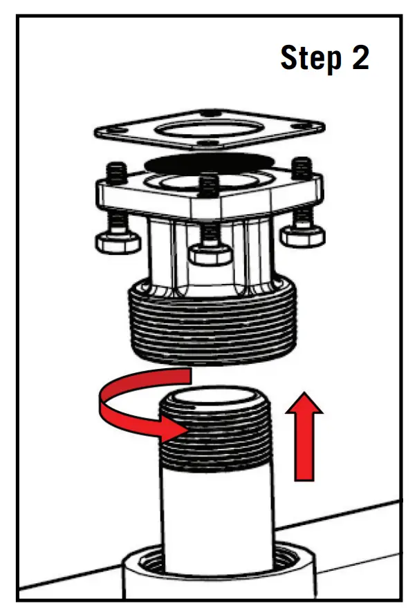
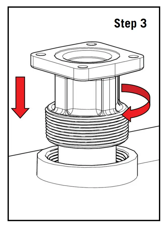
Step 3: Thread inlet bung with attached suction pipe onto tank 1.5 to 2.5 turns past hand tight. Use appropriate sealant for fuel transfer.
Step 4: (Only if Step 1 utilized) Place screen in screen pocket on the inlet bung, mount gasket, then place pump on tank bung. Align holes and insert (4) 1/4″ bolts and tighten with 7/16″ wrench to 40 in.-lbs. minimum. Step 5: Remove junction box cover via (2) T-25 screws and locate wires. DC Voltage: 2 wires, Black and Red; AC Voltage: 3 wires, Black, White, and Green which is attached to internal ground screw. Ensure that gasket remains in place upon re-attachment of junction box.
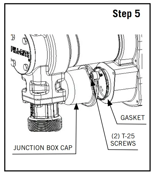
Step 5: Remove junction box cover via (2) T-25 screws and locate wires. DC Voltage: 2 wires, Black and Red; AC Voltage: 3 wires, Black, White, and Green which is attached to internal ground screw. Ensure that gasket remains in place upon re-attachment of junction box.
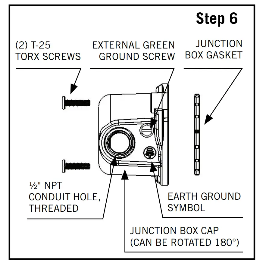
Step 6: Feed wires from power source through NPT† opening into junction box. For DC models, use the black cable connector* . For AC models, attach conduit directly to NPT† opening.
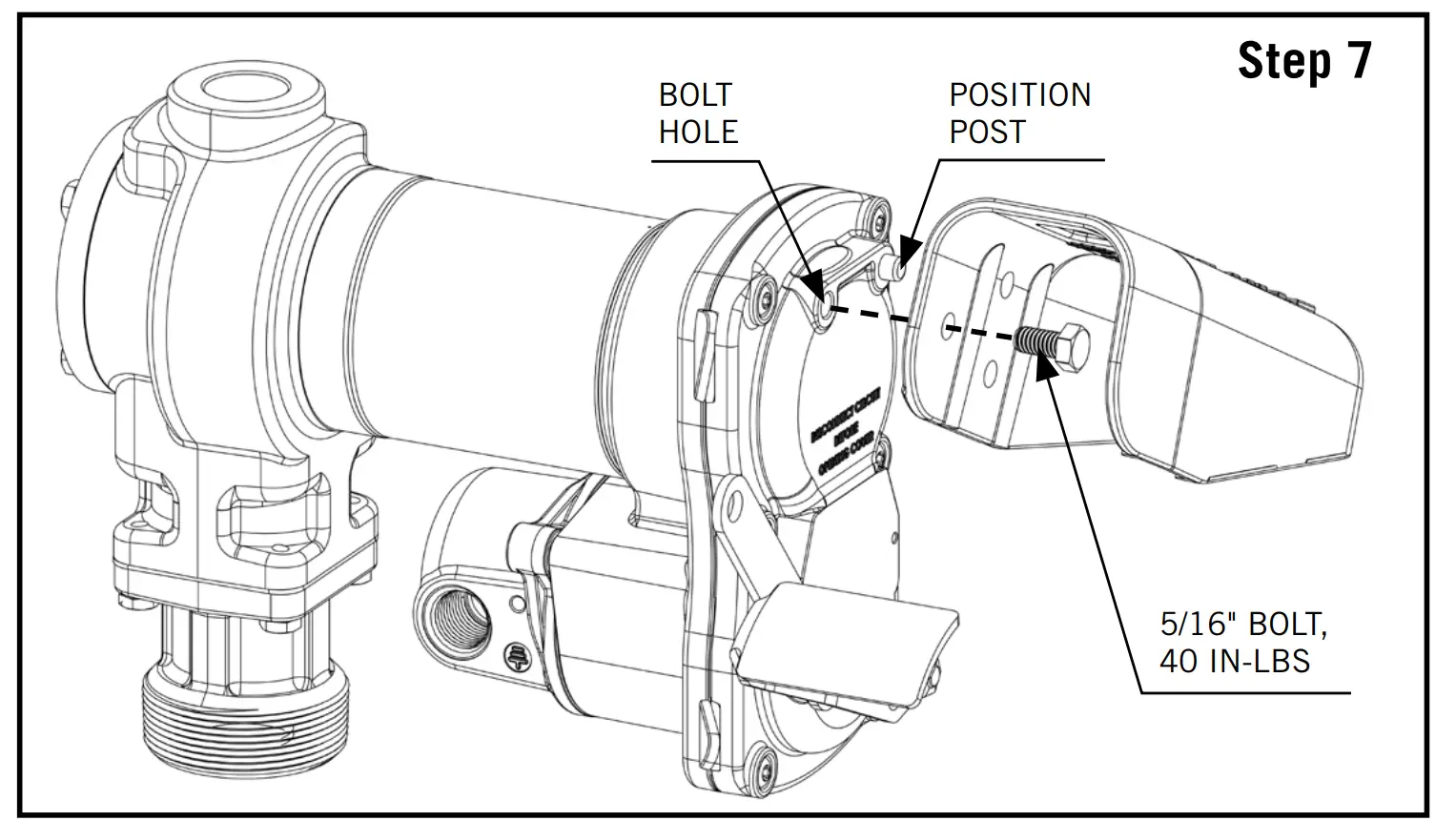
Step 7: Nozzle boot is attached to switch plate via (1) 5/16″ bolt torqued to 40 in-lbs. The nozzle boot has two available position placements.
![]() Maintain a minimum 1-2″ separation from pipe end to bottom of tank.
Maintain a minimum 1-2″ separation from pipe end to bottom of tank.
* Black cable gland only included with DC models
1/2″ NPT to cable gland, bronze fitting per ATEX on HE Models
Wiring Instructions
FR1200 / FR2400 / FR4200 / FR4400 / SD1200 Series DC Transfer Pump
![]()
Electrical wiring should be performed ONLY by a licensed electrician in compliance with local, state, and national electrical codes (NEC/ANSI/NFPA 30, NFPA 30A, and NFPA 70) as appropriate to the intended use of the pump. Threaded rigid conduit, sealed fittings, and conductor seal should be used where applicable. The pump must be properly grounded.
Improper installation or use of this pump can result in serious personal injury or death.
Do not connect the positive or negative power to the green ground/earth screw or ground/earth wire as this could cause a fire.
Do not attempt to power the pump from vehicle wiring smaller than 12 AWG such as the cigarette lighter wire because these thin wires could overheat and cause a fire.
For wiring up to upfitter switches, please contact Fill-Rite Technical Support at 1 (800) 720-5192 (M-F, 8am 5pm ET).
![]()
Fill-Rite DC fuel pumps are designed to operate at the rated nameplate voltage. Series FR1200, FR4200, and SD1200 are rated for 12V DC while FR2400 and FR4400 are rated for 24V DC. Regardless of how supply line power is provided (i.e. via a battery or hard line), Fill-Rite requires the circuit contain a fuse to prevent against electrical shorts. For 12V
DC, a 30 amp fuse is necessary while for the 24V DC circuit, a 20 amp fuse.
Voltage drop in wiring varies depending on the distance from the battery to the pump and the gauge of the wire used.
If the distance is greater than the supplied 18′ 12 AWG power cable*, refer to local, state, and national electrical codes to ensure the wire is of the correct size for this application.
The following chart is to be used as a reference and is not a substitute for electrical codes:
Maximum Linear Distance (FT) of Stranded Copper Wire Length by Gauge | ||||
| 10 | 8 | 6 | 4 | 2 |
27′ | 44’ | 69; | 110’ | 175’ |
*12 AWG power cable not supplied with pump only models
![]()
Electrical bonding is the process of connecting metallic parts such as a fuel storage tank or transfer pump which may be exposed to electrical faults to a grounding conductor to ensure a low-resistance path to the ground. Bonding also provides a path for static electricity and induced voltages to drain out through the grounding path. The most common way to bond is with a copper wire.
If the intention is to operate either a 12V or 24V DC fuel transfer pump from a power supply other than a vehicle battery system, please contact Fill-Rite Technical Support at 1 (800) 720-5192 (M-F, 8am-5pm ET).
Instructions Before Proceeding with DC Wiring
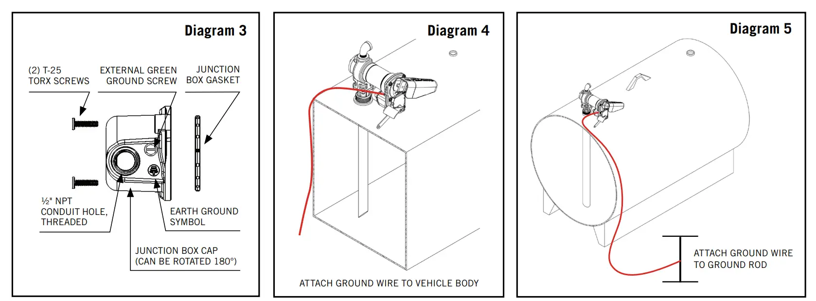
The pump needs to be electrically bonded to a vehicle frame for mobile tanks or a ground rod for stationary tanks. To electrically bond pump for mobile application, remove the external factory installed green bonding screw located on the junction box cover (Diagram 3). Insert this screw through eyelet of furnished green bonding wire assembly and refasten it securely to the junction box. The other end of the wire is to be stripped of insulation and the bare wire securely bonded to the vehicle or on/off road trailer frame for mobile tanks (Diagram 4). For bonding with stationary tanks, attach a ground wire to a ground rod and the tank itself (Diagram 5). The distance may be greater than the supplied grounding wire.
Wiring Instructions
- Remove pump’s electrical junction box cover and straighten the red and black wire.
- Screw the furnished cable connector into 1/2″ NPT conduit opening on the junction box.
3. Strip 3″ of the outer covering from one end of the furnished electrical supply cable.* Be careful not to damage the black and red wire insulation. - Loosen cable connector nut and pass the stripped end of the furnished cable through the cable connector. Tighten the cable connector nut.
- Strip 1/2″ of the insulation from the ends of the red and black cable wires. Using the furnished wire nuts, connect the cable wires to the pump wires matching the colors.
IMPORTANT: Be sure no bare wire is exposed. - Fold wires into junction box and replace, making sure the cover gasket is in place. Make sure all screws are seated so there is no space between the frame and the junction box (see Step 6 diagram on Page 6). *12 AWG cable not supplied with pump only models
Mobile Tank Wiring to a Vehicle Electrical System
- Before electrical installation, place the switch lever into the OFF position to prevent accidental spillage once power is engaged to the motor.
- Pass the electrical wires to the source of the vehicle power system, supporting as necessary and protecting them from sharp edges, heat, or anything that could cause damage.
- To determine if the vehicle electrical system is negative (-) or positive (+) ground, check the battery marking of the terminal that is wired to the vehicle frame or motor block. The red wire from the pump will connect to positive battery post and the black wire from the pump will connect to negative battery post. These instructions focus on COMMON negative ground systems. UNCOMMON positive systems are a rare occurrence. Reference the drawing on Page 9 for information on positive ground systems.
- Fill-Rite requires installing a fuse holder and fuse (not provided) for protection of the purchased pump. Attach one end of the fuse holder to the end of the ungrounded wire, making a solid connection. The other end of the fuse holder is then attached to the ungrounded side of the battery, as close to the battery as possible. Make a solid electrical connection to the grounded side of the battery with the remaining wire. Utilizing a battery terminal connection (not provided by Fill-Rite) is required for completion of the electrical circuit.
- Check all connections to make sure they are connected per instructions and all electrical codes. Install fuse (30 amp fuse for 12V DC; 20 amp fuse for 24V DC) into the fuse holder. Installation is now complete.
Mobile Tank Wiring to a Non-Vehicle System
While rare, there are instances where a 12V or 24V DC Fill-Rite fuel pump does not operate from a vehicle’s electrical system. In these cases, we recommend calling Fill-Rite Technical Support at 1 (800) 720-5192 (M-F, 8am-5pm ET) to discuss your specific situation. Most of these applications will require equipment not supplied by Fill-Rite. In addition, we want to ensure that the circuit will be able to handle the necessary power requirements of the pump.
Stationary Tank Wiring
- Before electrical installation, place the switch lever into the OFF position to prevent accidental spillage once power is engaged to the motor.
- Fill-Rite requires installing a fuse holder and fuse (not provided) for the protection of the purchased pump.
- Attach one end of the fuse holder to the red pump wire, as close to the battery or power source as possible. Make a solid connection to the positive terminal of the power source with the other end of the fuse holder. Make a solid connection with the black pump wire to the negative terminal of the power source.
- Check all connections to make sure they are connected per instructions and all electric codes.
- Install fuse (30 amp fuse for 12V DC; 20 amp fuse for 24V DC) into the fuse holder.
- The installation is now complete.
Negative Ground System (Common)
This electrical system is common within most vehicles utilizing a 12V DC power source. In this instance, the positive battery terminal supplies power to all devices such as the ignition system. The negative (-) terminal is connected to the vehicle’s frame.
Fuse to be located outside of hazardous area, as close to the power source as possible. If the wiring from the power source to the pump is greater than 18′, refer to the applicable Electrical Code (national, international, or local) to ensure the wire is of the correct size for the application.
![]()
Positive Ground System (Uncommon)
This electrical system is uncommon within most vehicles utilizing a 12V DC power source. The chassis of the vehicle is connected to the positive (+) terminal of the battery.
Fuse to be located outside of hazardous area, as close to the power source as possible. If the wiring from the power source to the pump is greater than 18′, refer to the applicable Electrical Code (national, international, or local) to ensure the wire is of the correct size for the application.
![]()
115V AC Wiring Instructions for FR600 / SD600 AC Fuel Transfer Pumps
![]()
- All pumps will operate at the rated nameplate voltage.
- AC power should be supplied to the pump from a dedicated circuit with a 15 amp circuit protection. No other equipment should be powered by this circuit.
- Wiring must be of sufficient size to carry the correct current for the pump.
- Voltage drop will vary with distance to pump and size of wire; refer to the National Electrical Code (NEC) or local codes for voltage drop compensation to be sure you are using the correct size wire for your application. Undersized wires can overheat and cause a fire.
- Ensure proper grounding to avoid electrocution.
- Each Fill-Rite motor is labeled as explosion-proof for hazardous locations Class I / Division 1. It is highly recommended that any repairs be done by an authorized distributor to avoid voiding the warranty. It is very important to maintain the explosion-proof integrity of the motor and system components.
- Electrical wiring should be performed ONLY by a licensed electrician in compliance with local, state, and national electrical codes (NEC/ANSI/NFPA 70, NFPA30, and NFPA 30A) as appropriate to the intended use of the pump.
The pump must be properly grounded. Improper installation or use of this pump can result in serious bodily injury or death.
![]()
- Ground wire in supply wiring MUST be connected to the ground screw inside the junction box.
![]()
Voltage drop in wiring varies depending on the distance from the electrical source to the pump and the gauge of the wire used. Fill-Rite recommends referring to national, international, or local electrical codes to ensure the wire is of the correct size for your application. The following chart is to be used as a reference and is not a substitute to electrical codes.
| Maximum Linear Distance (FT) of Solid and Stranded Copper Wire Length by Gauge | ||||||||
| AWG | 16 | 14 | 12 | 10 | 8 | 6 | 4 | |
| Wire | Solid | 39 | 62 | 99 | 158 | 250 | ||
| Stranded | 38 | 61 | 96 | 154 | 245 | 389 | 620 | |
Wiring Procedure
- Remove the junction box cover and straighten the wires to make sure the stripped wire ends are accessible outside the junction box.
- Install rigid conduit and appropriate wiring from power source to the junction box to maintain the explosion proof integrity.
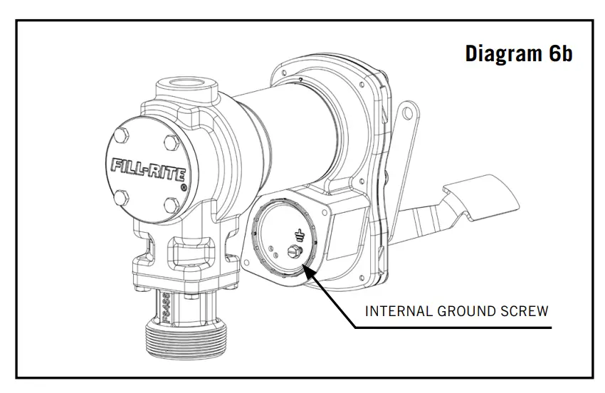
- Connect the pump wires to the power supply lines according to the wiring diagram. Be certain to properly insulate the connections with the appropriate wire nuts or other connectors. NOTE: The ground wire MUST be connected. Ground wire connection is inside the junction box (Diagram 6b).
- Fold the wires back into the junction box and replace the cover, making sure the cover gasket is in place.
Pump Junction Box (FR/SD600 Series AC Fuel Transfer Pumps)
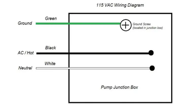
115V AC Wiring Diagram for FR/SD600 AC Fuel Transfer Pumps.
A ground wire must be included within the supply line power cable. This wire must be connected to the ground screw terminal on the inside of the junction box surface.
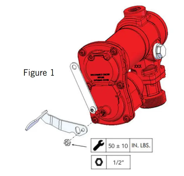
Switch Level Installation Instructions
Effective March 7, 2022, the fuel transfer pump on/off switch lever will need to be installed in the field. Please see Figure 1 for a visual guide on the proper installation of this lever.
Operation Instructions
![]() Always keep the nozzle in contact with the container being filled during the filling process to minimize the possibility of static electricity build up. A spark around flammable vapors will cause an explosion resulting in death or serious injury
Always keep the nozzle in contact with the container being filled during the filling process to minimize the possibility of static electricity build up. A spark around flammable vapors will cause an explosion resulting in death or serious injury
- If equipped, reset meter to “0” (do not reset while in use as this will cause damage to the meter).
- Remove dispensing nozzle from nozzle boot.
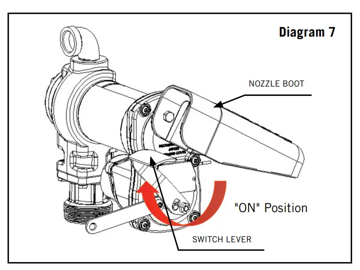
- Move the switch lever to the “ON” position to power the pump (Diagram 7).

- Insert the dispensing nozzle into the container to be filled.
- Operate the nozzle to dispense fluid; release nozzle when the desired amount of fluid has been dispensed.
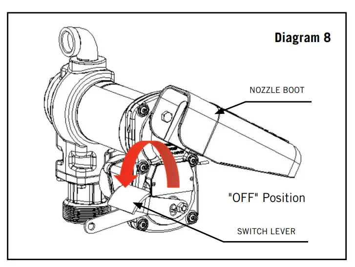
- Move switch lever to the “OFF” position (Diagram 8) to turn off the pump.
- Remove the dispensing nozzle from the container being filled and store it in the nozzle boot.
Security
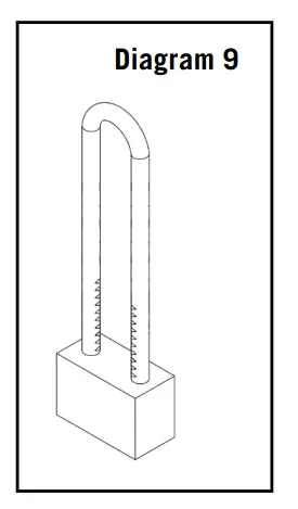
Your Fill-Rite fuel transfer pump is equipped with a locking link located next to the switch lever for security. With the pump turned off and the nozzle in the stored position, a padlock can be inserted through the locking link and the nozzle handle. Fill-Rite recommends a commercial grade laminated steel padlock with an adjustable shackle (Diagram 9).
Troubleshooting
The following troubleshooting guide is provided to offer basic diagnostic assistance in the event you encounter abnormal service from your Fill Rite fuel transfer pump. If you have questions, please feel free to contact Fill Rite Technical Support at 1 (800) 720-5192 (M-F, 8am-5pm ET) or by email at [email protected].
![]()
Please disconnect all power supply sources from either your AC or DC pump prior to performing any service or maintenance, as well as relieve any pressure within either the suction tube or discharge hose. Failure to do so can result in damage to the equipment and personal injury or death.
| Symptom | Cause | Cure |
| Pump will not prime | Suction line problem | Check for leaks or restrictions in suction line |
| Bypass valve open | Remove and inspect valve; must move freely and be free of debris | |
| Vanes sticking | Check vanes and rotor slots for nicks, burrs, and wear | |
| Excessive rotor or vane wear | Inspect rotor and vanes for excessive wear or damage; replace if necessary | |
| Automatic nozzle | Remove to prime pump | |
| System blockages | Check filter and bypass valve for debris; remove nozzle and test flow with pump ON | |
| Low capacity | Excessive dirt in screen | Remove and clean screen |
| Suction line problems | Check for leaks or restrictions in suction line | |
| Bypass valve sticking | Remove and inspect valve; must move freely and be free of debris | |
| Outlet blocked | Check pump outlet hose, nozzle, and filter for blockage | |
| Vanes sticking | Check vanes and rotor slots for wear; replace if necessary | |
| Excessive rotor or vane wear | Inspect rotor and vanes for excessive wear or damage; replace if necessary | |
| Hose or nozzle damage | Replace hose or nozzle (Fill-Rite recommends UL-rated hoses and nozzles) | |
| Plugged filter | Replace filter | |
| Low fluid level | Fill tank | |
| Pump runs slowly | Incorrect voltage | Check incoming supply line voltage |
| Vanes sticking | Inspect vanes and rotor slots for nicks, burrs, and wear | |
| Wiring problem | Check for loose connections | |
| Motor problem | Contact Fill-Rite Technical Support at 1 (800) 720-5192 (M-F, 8am-5pm ET) | |
| Motor stalls, fuse blows, thermal protector trips repeatedly | Bypass valve sticking | Remove and inspect valve; must move freely and be free of debris |
| Low voltage | Check incoming supply line voltage | |
| Excessive rotor or vane wear | Check rotor and vanes for excessive wear or damage | |
| Debris in pump cavity | Clean debris from pump cavity | |
| Motor overheats | Transferring high viscosity fluids | These fluids can only be pumped for short periods of time (less than 30 minute duty cycle) |
| Clogged screen | Remove inlet and clean screen | |
| Restricted suction pipe | Remove and clean pipe | |
| Motor failure | Contact Fill-Rite Technical Support at 1 (800) 720-5192 (M-F, 8am-5pm ET) | |
| Pump rotor lock-up | Clean and check pump rotor and vanes | |
| Motor inoperable | No power | Check incoming supply line power |
| Wiring issue | Use multimeter to isolate issue with supply line power | |
| Motor failure | Contact Fill-Rite Technical Support at 1 (800) 720-5192 (M-F, 8am-5pm ET) | |
| Locked rotor | Clean and check pump rotor; repair as needed with KIT120RG | |
| Incorrect/loose wiring | Verify correct wire size with local, state, and national electric codes | |
| Fluid leakage | Bad O-ring gasket | Check and replace all O-ring gaskets (Rotor Cover / Inlet Flange / Bypass Cap) |
| Dirty/bad shaft seal | Replace shaft seal with KIT120SL | |
| Incompatible fluid | Refer wetted parts list on Page 14 to the fluid manufacturer | |
| Loose fasteners | Tighten fasteners | |
| Pump hums but will not operate | Motor failure | Contact Fill-Rite Technical Support at 1 (800) 720-5192 (M-F, 8am-5pm ET) |
| Broken rotor key | Remove all debris and replace key |
Specifications and Models
A series of fuel transfer pumps with UL/cUL, ATEX, IECEx, CE, EAC, and INMETRO certifications that are compatible with gasoline, diesel fuel, blended fuels such as biodiesel up to 20%, gasoline with up to 15% ethanol, mineral spirits, and kerosene
| Product Parts | Product Materials |
| Pump Housing | Cast Iron |
| Rotor | Powdered Iron |
| Vane | Sintered Bronze |
| Strainer Mesh | Stainless Steel |
| Wetted Components | Buna-N, Fluorocarbon, Ceramic, Cork, Thermoset, Steel, Stainless Steel |
| Motor | Description | FR1200 | FR4200 | SD1200 | FR4400 | FR2400 | FR600 | SD600 | |
| Voltage, Supply (DC/AC) | 12V DC | 24V DC | 115V AC / 60HZ | ||||||
| Power (HP) | 1/4TH | 1/6TH | |||||||
| Amps (Full Load) | 26 | 28 | 26 | 18 | 15 | 2.5 | |||
| Amps (Rated) | 20 | 19 | 20 | 13 | 10 | 2.0 | |||
| RPM | 2600 RPM | 2000 RPM | |||||||
| Power Cord* | Length | 18′ | 15′ | 18′ | Not Included | ||||
| AWG | 12 | ||||||||
| Duty Cycle | 30 Minutes (on), then 30 Minutes (off) | ||||||||
| Thermal Protection (motor) | Yes | ||||||||
| Required Circuit Protection | 30 AMP | 20 AMP | 15 AMP | ||||||
| Pump | Description | FR1200 | FR4200 | SD1200 | FR4400 | FR2400 | FR600 | SD600 | |
| Maximum GPM | 15 | 20 | 13 | 20 | 15 | 13 | |||
| Bypass Pressure | 16 PSI | ||||||||
| Minimum Dry Vac | 5 IN-HG | ||||||||
| At Sea Level 70° F (21.1° C) | Suction Lift | 8′ Maximum | |||||||
| Outlet Head | 37′ Maximum | ||||||||
| Inlet | 1″ NPT | ||||||||
| Outlet | 3/4″ NPT* | 1″ NPT* | 3/4″ NPT* | 1″ NPT* | 3/4″ NPT* | ||||
| Mount | H Models: 2″ NPT Bung Adapter with 1″ NPT Inlet HE Pump Only Models: 2″ BSPT Bung Adapter with 1″ BSPP Inlet | ||||||||
| Warranty | Limited Lifetime Warranty† | 1 Year | Limited Lifetime Warranty† | 1 Year | |||||
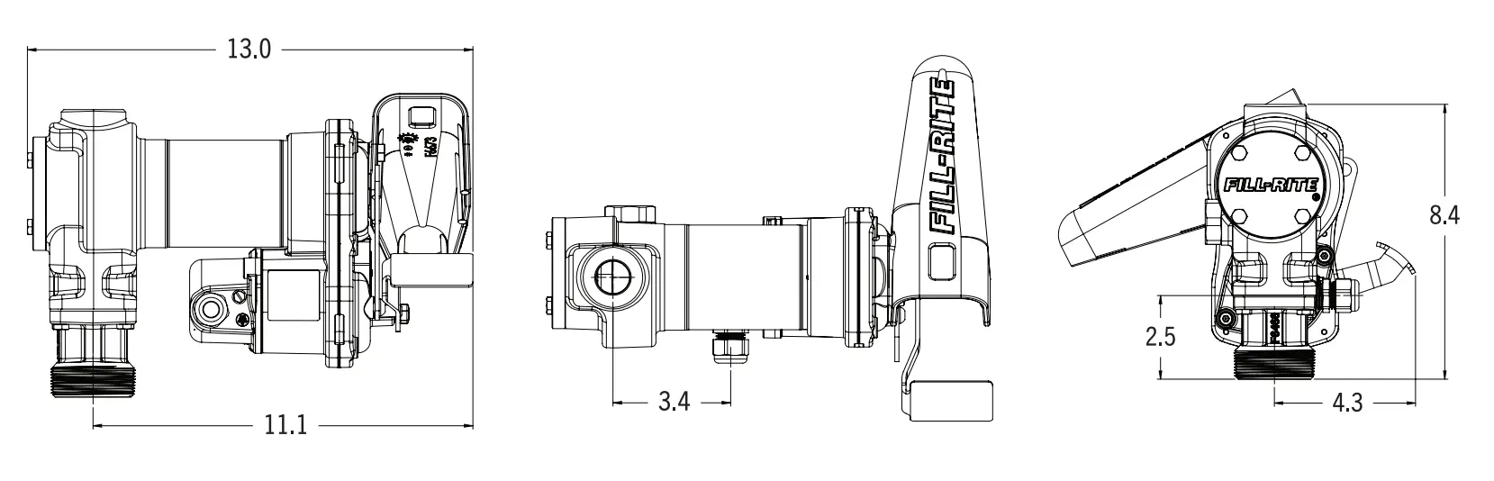
FR1200, FR2400, FR4400, FR600, SD1200, and SD600 (Dimensions displayed in inches)
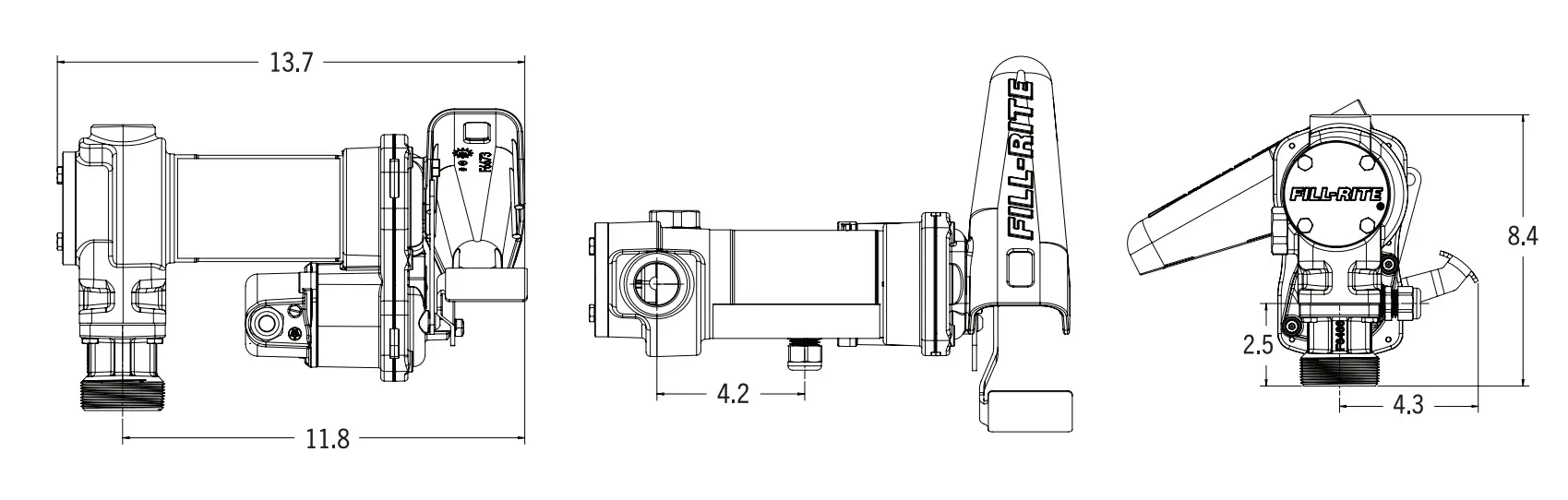
FR4200 (Dimensions displayed in inches)
H-Series Model Information: FR1200, FR2400, FR4200, FR4400, FR600, SD1200, SD600
| Model Number | Nozzle | Hose | Meter | Inlet Tube | Power Cord | Special | Voltage | Outlet |
| FR1204H | Pump Only Model | 12V C | 3/4″ | |||||
| FR1210H | Manual | 12′ | Metal Telescoping 20″ – 34 ½” | 12 AW at 18′ | ||||
| FR1210HA | Auto Gasoline | 12′ | ||||||
| FR1210HA1 | Auto Diesel | 12′ | ||||||
| FR1210HARC | Auto Arctic | 15′ | Swivel | |||||
| FR1210HN | ||||||||
| FR1211H | Manual | 12′ | 807C | |||||
| FR1211HL | Manual | 12′ | 807CL | |||||
| FR1211HLN | 807CL | |||||||
| FR1211HN | 807C | |||||||
| FR1219H | Manual | 12′ | TT10AN | |||||
| FR1220HDSQ | Auto Diesel | 18′ | Swivel | |||||
| FR1220HDSFQ | Auto Diesel | 18′ | Swivel Filter | |||||
| FR2404H | Pump Only Model | 24V DC | ||||||
| FR2410H | Manual | 12′ | Metal Telescoping 20″ – 34 ½” | 12 AWG at 18′ | ||||
| FR2411H | Manual | 12′ | 807C | |||||
| FR2411HL | Manual | 12′ | 807CL | |||||
| FR4204H | Pump Only Model | 12V DC | 1″ | |||||
| FR4210H | Manual | 12′ | Metal Telescoping 20″ – 34 ½” | 12 AWG at 18′ | ||||
| FR4210HARC | Auto Arctic | 20′ | Swivel | |||||
| FR4210HB | Ultra Hi-Flow | 12′ | ||||||
| FR4210HD | Auto Diesel | 12′ | ||||||
| FR4210HDS | Auto Diesel | 12′ | Swivel | |||||
| FR4210HBFQ | Ultra Hi-Flow | 18′ | 10 AWG at 25′ with clamps | Filter | ||||
| FR4210HN | 12 AWG at 18′ | |||||||
| FR4211H | Manual | 12′ | 901C | |||||
| FR4211HL | Manual | 12′ | 901CL | |||||
| FR4211HLN | 901CL | |||||||
| FR4211HN | 901C | |||||||
| FR4219H | Manual | 12′ | TT10AN | |||||
| FR4220HDSQ | Auto Diesel | 18′ | Swivel | |||||
| FR4220HDSFQ | Auto Diesel | 18′ | Swivel Filter | |||||
H-Series Model Information: FR1200, FR2400, FR4200, FR4400, FR600, SD1200, SD600 (continued)
| Model Number | Nozzle | Hose | Meter | Inlet Tube | Power Cord | Special | Voltage | Outlet |
| FR4406H | Pump Only Model | 24V DC | 1″ | |||||
| FR4410H | Manual | 12′ | Metal Telescoping 20″ – 34 ½” | 12 AWG at 18′ | ||||
| FR604H | Pump Only Model | 115V AC | 3/4″ | |||||
| FR610H | Manual | 12′ UL | Metal Telescoping 20″ – 34 ½” | |||||
| FR610HA | Auto Gasoline | 12′ UL | ||||||
| SD1202H | Manual | 10′ | PVC, 15 ¼” – 29 ¼” | 12 AWG at 15′ | 12V DC | |||
| SD1202HA | Auto Gasoline | 10′ | 12 AWG at 15′ | |||||
| SD602H | Manual | 12′ UL | PVC, 15 ¼” – 43 ¼” | 115V AC | ||||
HE-Series Model Information: FR1200E, FR2400E, FR4200E, FR4400E
| Model Number | Nozzle | Hose | Meter | Inlet Tube | Power Cord | Voltage | Outlet |
| FR1205HE | Pump Only Model | 12V DC | 3/4″ | ||||
| FR1210HE | Manual | 12′ | Metal Telescoping 20″ – 34 ½” | 12 AWG at 18′ | |||
| FR1210HEA | Auto Gasoline | 12′ | |||||
| FR1211HEL | Manual | 12′ | 807CL | ||||
| FR1211HELA | Auto Gasoline | 12’ | 807CL | ||||
| FR2405HE | Pump Only Model | 24V DC | |||||
| FR2410HE | Manual | 12′ | Metal Telescoping 20″ – 34 ½” | 12 AWG at 18′ | |||
| FR2410HEA | Auto Gasoline | 12’ | |||||
| FR2411HEL | Manual | 12′ | 807CL | ||||
| FR2411HELA | Auto Gasoline | 12′ | 807CL | ||||
| FR4205HE | Pump Only Model | 12V DC | 1″ | ||||
| FR4210HE | Manual | 12′ | Metal Telescoping 20″ – 34 ½” | 12 AWG at 18′ | |||
| FR4210HEB | Ultra Hi-Flow | 12’ | |||||
| FR4210HEBL | Ultra Hi-Flow | 12′ | 901CL | ||||
| FR4211HEL | Manual | 12′ | 901CL | ||||
| FR4405HE | Pump Only Model | 24V AC | |||||
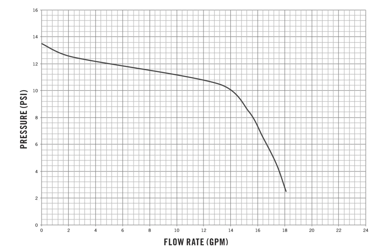
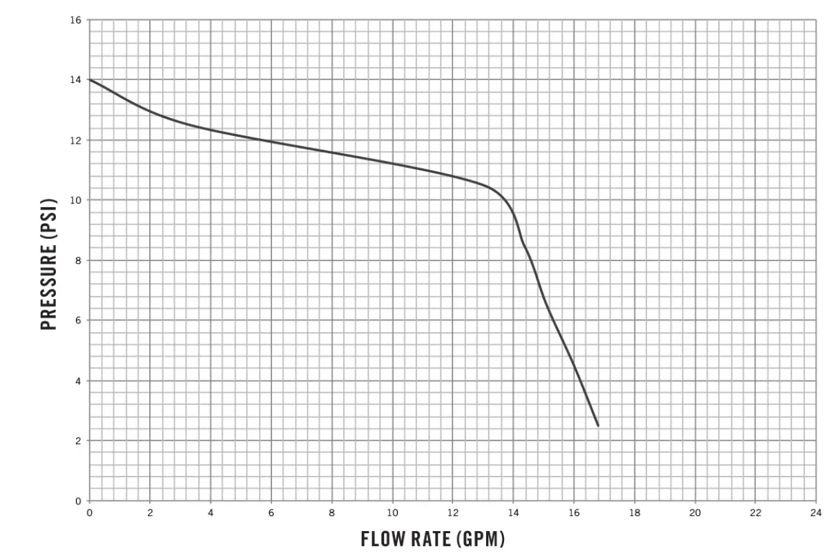
1200 Series Performance Curve
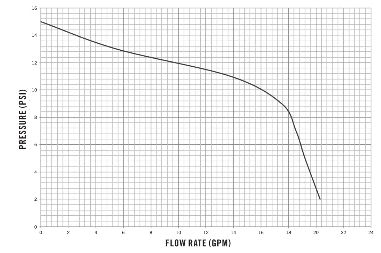
2400 Series Performance Curve
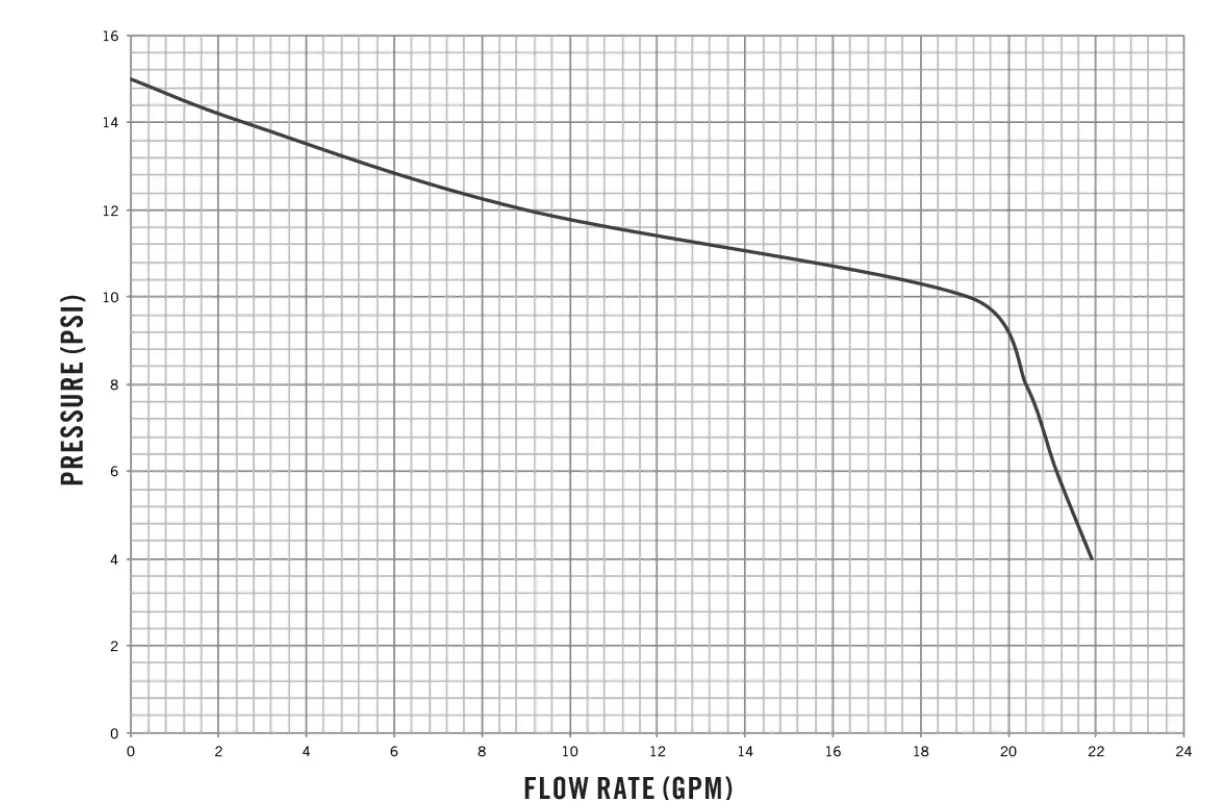
4200 Series Performance Curve
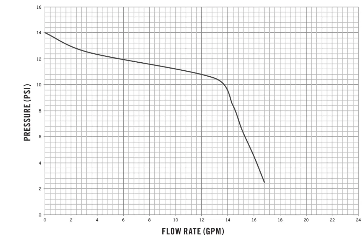
4400 Series Performance Curve
600 Series Performance Curve
Accessories
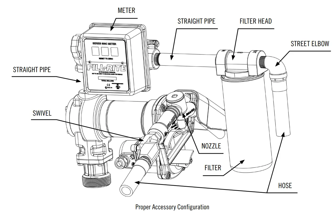
| Accessory | Series | Outlet Size | Notes | ||
| 3/4″ | 1″ | ||||
| Nozzle | Manual | FRHMAN075S | FRHMN1005 | Gasoline/Diesel | |
| Automatic | Hi-Flow | N075UAU10 | N100DAU12 | Red Boot | |
| N075DAU10 | N100DAU12G | Green Boot | |||
| Arctic | FRNA075DAU10 | FRNA100DAU00 | Cold Weather (-40˚F/˚C) | ||
| Ultra Hi-Flow | N100DAU13 | Red Boot | |||
| N100DAU13G | Green Boot | ||||
| N100DAU13Y | Yellow Boot | ||||
| Hose | 12′, UL Rated | 700F3135 | 300F7773 | Gasoline, Diesel, Kerosene, and Petroleum Oils compatible | |
| 12′ | FRH07512 | FRH10012 | |||
| 14′ | FRH07514 | FRH10014 | |||
| 20′ | FRH07520 | FRH10020 | |||
| Meter | Mechanical | 800 | 807CMK | Gallons | |
| 807CLMK | Liters | ||||
| 900 | 901CMK4200 | Gallons | |||
| 901CLMK4200 | Liters | ||||
| Digital | 900 | 900CD | Programmable | ||
| 900CDP | Programmable with Integral Pulsa | ||||
| TT | TT10AB | BSPP, Aluminum | |||
| TT10ABC | BSPP, Nickel-Plated | ||||
| TT10AN | NPT, Aluminum | ||||
| TT10ANC | NPT, Nickel-Plated | ||||
| Swivel | Multi-Plane | S075H1314 | S100H1315 | 360˚ Rotation | |
| Filter | Heads | 1200KTG9075 (F18 Filters) | 700ACCF7017 (F40 Filters) | Gasoline/Diesel compatible | |
| Particulate | F1810PMO (10 Micron/18GPM) | F4010PM0 (10 Micron/40 GPM) | |||
| F4030PM0 (30 Micron/40GPM) | |||||
| Hydrosorb | F1810HMO (10 Micron/18GPM) | ||||
Pump Service Kits
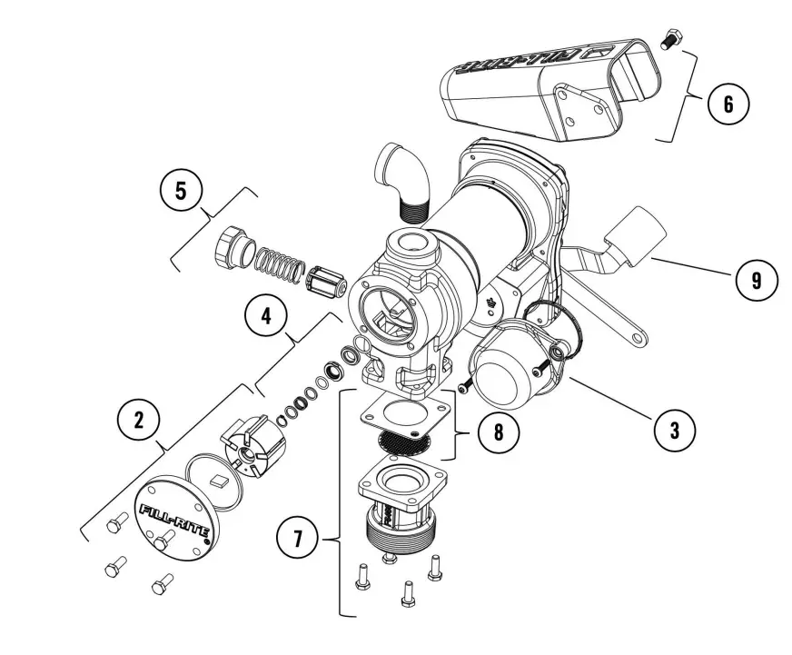
# | Kit | Description | Parts |
1 | KIT120BD* | BioDiesel Kit | O-ring, inlet and bypass cap seals, bypass valve poppet |
2 | KIT120RGG | Rotor and Vane Kit | Rotor cover, rotor, vanes, rotor key, O-ring seal, attaching hardware |
3 | KIT120JCH | Junction Cover Kit | Junction cover, seal, fasteners |
4 | KIT120SL | Seal Kit | O-ring, shaft seals, retainer clip |
5 | KIT120BV | Bypass Service Kit | Bypass valve, valve spring, bypass cap, O-ring seal |
6 | KIT120NB | Nozzle Boot Kit | Nozzle boot, attaching hardware |
7 | KIT120BG | Inlet Flange Kit | Inlet flange (bung), attaching hardware, inlet seal, screen |
8 | KIT120SG | Inlet Gasket and Screen | Gasket for inlet (bung) and screen |
9 | KIT120SWH | Switch Lever Kit | Switch lever, mounting hardware |
Safety Testing Approvals
The Fill-Rite line of pumps have been safety tested for regulatory compliance. This product family is approved by UL/cUL. For the “E” series products they are approved to ATEX, IECEx, INMETRO, EAC, and CE.
FILL-RITE H-Series Fuel Transfer Pumps
Thank You!
Thank you for your loyalty to the Fill-Rite® brand of fuel transfer pumps. Your safety is important, so please read and thoroughly understand the procedures set forth in this manual. In addition, please save these instructions for future reference and record the model, serial number, and purchase date of your fuel transfer pump. Protect yourself as well as those around you by observing all safety instructions and adhering to all danger, warning, and caution symbols. Please register your Fill-Rite® product via info.fillrite.com/product_registration.
IMPORTANT RETURN POLICY
Please do not return this product to the store. For all warranty and product questions, please contact Fill-Rite Technical Support at 1 (800) 720-5192 or via email at [email protected] (M-F, 8 AM – 5 PM ET).
MODEL#
SERIAL#
PURCHASE DATE:
Limited Warranty Policy
Fill-Rite Company warrants the goods manufactured shall be free from defects of materials and workmanship. Specific warranty details for individual products can be found at fillrite.com.
H-Series Fuel Transfer Pumps Have the Following Features
- Adjustable Electrical Junction Box
Rotates 180 degrees to provide ease of electrical wiring installation in tight quarters no matter the inlet bung location - Reliable, Heavy-Duty Power Switch Lever
Features a cast metal stop that withstands heavy use in the most rugged environments - Locking Bar Defense
Elongated bar simplifies the pad locking process to prevent theft - Focused Component Weight Reduction
Preserves expected heavy-duty performance while improving installation ease - Premium Paint Shield
An exemplary corrosion resistant barrier for long field life - Thermally Protected Motor
Prevents overheating to ensure maximum motor life - Telescoping Inlet Metal Suction Pipe*
Adjustable from 20 to 34 inches in length, allowing for universal installation on a multitude of tank sizes and shapes
*Not included with SD models - Intake Strainer Safeguard
Protects the pump by blocking particles created by contamination - Certifications – UL, cUL
About This Manual
From initial concept and design through final production, your Fill-Rite fuel transfer pump is built to provide years of trouble-free use. To ensure the safety of yourself and those around you, it is critical that this manual is read in its entirety prior to attempting to install or operate your new purchase. We strongly urge that any installer and operator become familiar with the terms, diagrams, and technical data in this manual and pay close attention to warning symbols and definitions. At Fill-Rite, your satisfaction with our products is paramount. If you have questions or need assistance with your product, please contact Fill-Rite Technical Support at 1 (800) 720-5192 (M-F, 8am-5pm ET).
Symbols and Definitions
![]() Indicates a hazardous situation which, if not avoided, will result in death or serious injury.
Indicates a hazardous situation which, if not avoided, will result in death or serious injury.
![]() Indicates a hazardous situation which, if not avoided, could result in death or serious injury.\
Indicates a hazardous situation which, if not avoided, could result in death or serious injury.\
![]() Indicates a hazardous situation which, if not avoided, could result in moderate or minor injury.
Indicates a hazardous situation which, if not avoided, could result in moderate or minor injury.
![]() Indicates information considered important but not directly hazard related.
Indicates information considered important but not directly hazard related.
Before You Begin
Fueling Requirements
The Fill-Rite FR1200, FR2400, FR4200, FR4400, FR600 as well as SD1200 and SD600 models are designed and approved for use with the following flammable and combustible fluids: gasoline and gasoline blends up to 15% or E15, diesel, biodiesel blends up to 20% or B20, kerosene, and mineral spirits.
Please take all necessary precautions when handling flammable liquids.
Power Source Requirements
Depending on the Fill-Rite model, supply line power will either be 12V DC, 24V DC, or 115V AC. The pump motor nameplate located next to the switch lever will provide detailed electrical information. Please refer to the appropriate electrical instructions found starting on Page 7 (DC power) or Page 10 (AC power).
Items that may be needed for installation:
Steel pipe wrench 14-24″, open end wrench or socket (7/16″, 11mm), T-25 Torx driver, utility knife, angle grinder or hacksaw (optional), wire cutters, wire stripper/crimper, and thread sealant (optional).
NOTE: Fill-Rite provides Teflon® tape for all models as listed on Page 16.
Safety Information
To ensure a safe installation and proper equipment operation, please read, understand, and adhere to all DANGER/WARNING/CAUTION and other NOTICES.
![]() Never smoke around or near a fuel tank or transfer pump. Open flames or a spark when pumping a flammable liquid will result in a fire. Improper electrical wiring or installation will result in serious injury or death.
Never smoke around or near a fuel tank or transfer pump. Open flames or a spark when pumping a flammable liquid will result in a fire. Improper electrical wiring or installation will result in serious injury or death.
![]() Electrical wiring should ONLY be performed by a licensed electrician in compliance with all local, state, and national electrical codes (NEC/ANSI/NFPA 30, NFPA 30A, and NFPA 70) as appropriate for the intended use of a Fill-Rite fuel transfer pump.
Electrical wiring should ONLY be performed by a licensed electrician in compliance with all local, state, and national electrical codes (NEC/ANSI/NFPA 30, NFPA 30A, and NFPA 70) as appropriate for the intended use of a Fill-Rite fuel transfer pump.
Threaded rigid conduit, sealed fittings, and conductor seal should be used where applicable and as defined by these codes.
This product must be properly bonded or grounded to avoid the build up of static electricity when handling flammable products. Static discharge may ignite vapors causing serious injury or death.
Fill-Rite pumps are not suited for use with water or fluids intended for human consumption. Do not use to fuel aircrafts.
To minimize static electricity build up, keep the nozzle in contact with the container being filled at all times during the filling process. Use only static wire conductive hose when pumping flammable liquid. Improper mechanical installation or use can result in serious injury or death.
![]() Threaded pipe joints and connections must be sealed with the appropriate sealant or sealant tape to prevent leaks.
Threaded pipe joints and connections must be sealed with the appropriate sealant or sealant tape to prevent leaks.
All Fill-Rite pump models are equipped with thermal overload protection by which the motor will shut off to prevent heat damage. If motor is turned off by a thermal overload, turn the switch lever to the OFF position. Once the motor has cooled sufficiently, turn the switch lever to the ON position to resume fuel transfer.
Some Fill-Rite models will restart automatically if the switch lever is not in the OFF position once the thermal protector resets. As good practice, always place the switch lever in the OFF position when the motor overheats.
![]() A filter should be used on the pump outlet to avoid contamination into the vehicle or equipment’s fuel tank. We recommend Fill-Rite filters for best results.
A filter should be used on the pump outlet to avoid contamination into the vehicle or equipment’s fuel tank. We recommend Fill-Rite filters for best results.
To prevent fuel storage tanks from shifting or tipping, refer to tank manufacturer’s guidelines on proper anchoring.
Installation
Your Fill-Rite pump is designed to be mounted on a fuel tank via a threaded inlet flange supplied with the pump. Typical installations are shown in Diagram 1 and 2. Your pump features an integral bypass valve to recirculate the fluid when the pump is operating with the nozzle closed.
![]() Do not use additional check valves or foot valves unless they have a proper pressure relief valve built into them.
Do not use additional check valves or foot valves unless they have a proper pressure relief valve built into them.
Please be aware that additional check valves will reduce flow rates.
A pressure-retaining fill cap can be used to reduce fuel loss through evaporation.
Threaded pipe joints and connections must be sealed with the appropriate sealant to prevent leaks.
Use caution to prevent cross-threading during installation which can cause damage to either or both the inlet flange as well as storage tank bung.
![]() In all tank applications, be sure the tank is properly secured per tank manufacturer’s guidelines.
In all tank applications, be sure the tank is properly secured per tank manufacturer’s guidelines.
Stationary Tank
For stationary fuel tanks, the pump mounts to the tank bung by way of the pump inlet flange. Given the different sizes of stationary fuel tanks, a custom suction or inlet pipe may be necessary. We recommend 1” NPT black iron pipe that is extended to a length of at least 1-2” from the bottom of the tank, with the bottom of the pipe cut to an angle between 30-45 degrees for improved flow.
A stationary tank must be equipped with a vent cap. (Diagram 1)
Mobile Tank
For mobile fuel tanks, the pump mounts to the tank bung by way
of the pump inlet flange.
For Telescoping Steel Suction Pipe
Allow telescoping tube to extend fully to the bottom of the tank.
For Custom or PVC Suction Pipe
To avoid penetrating the tank, we recommend leaving a minimum of 1-2” of the pipe off the bottom of tank. We further recommend cutting the suction pipe to a 30-45 degree angle for improved flow.
The mobile tank must be equipped with a vent cap. (Diagram 2)
Installation Procedure
Step 1: (Optional) Inlet Flange Removal Loosen (4) 1/4″ bolts using 7/16″ wrench or socket. Detach inlet bung from pump, retain bolts, screen, and gasket.
Step 2: Using either included suction pipe or custom pipe, thread pipe into inlet bung 1.5 to 2.5 turns past hand tight with pipe wrench. Use appropriate sealant for fuel transfer.
Step 3: Thread inlet bung with attached suction pipe onto tank 1.5 to 2.5 turns past hand tight. Use appropriate sealant for fuel transfer.
Step 4: (Only if Step 1 utilized) Place screen in screen pocket on the inlet bung, mount gasket, then place pump on tank bung. Align holes and insert (4) 1/4″ bolts and tighten with 7/16″ wrench to 40 in.-lbs. minimum. Step 5: Remove junction box cover via (2) T-25 screws and locate wires. DC Voltage: 2 wires, Black and Red; AC Voltage: 3 wires, Black, White, and Green which is attached to internal ground screw. Ensure that gasket remains in place upon re-attachment of junction box.
Step 5: Remove junction box cover via (2) T-25 screws and locate wires. DC Voltage: 2 wires, Black and Red; AC Voltage: 3 wires, Black, White, and Green which is attached to internal ground screw. Ensure that gasket remains in place upon re-attachment of junction box.
Step 6: Feed wires from power source through NPT† opening into junction box. For DC models, use the black cable connector* . For AC models, attach conduit directly to NPT† opening.
Step 7: Nozzle boot is attached to switch plate via (1) 5/16″ bolt torqued to 40 in-lbs. The nozzle boot has two available position placements.
![]() Maintain a minimum 1-2″ separation from pipe end to bottom of tank.
Maintain a minimum 1-2″ separation from pipe end to bottom of tank.
* Black cable gland only included with DC models
1/2″ NPT to cable gland, bronze fitting per ATEX on HE Models
Wiring Instructions
FR1200 / FR2400 / FR4200 / FR4400 / SD1200 Series DC Transfer Pump
![]()
Electrical wiring should be performed ONLY by a licensed electrician in compliance with local, state, and national electrical codes (NEC/ANSI/NFPA 30, NFPA 30A, and NFPA 70) as appropriate to the intended use of the pump. Threaded rigid conduit, sealed fittings, and conductor seal should be used where applicable. The pump must be properly grounded.
Improper installation or use of this pump can result in serious personal injury or death.
Do not connect the positive or negative power to the green ground/earth screw or ground/earth wire as this could cause a fire.
Do not attempt to power the pump from vehicle wiring smaller than 12 AWG such as the cigarette lighter wire because these thin wires could overheat and cause a fire.
For wiring up to upfitter switches, please contact Fill-Rite Technical Support at 1 (800) 720-5192 (M-F, 8am 5pm ET).
![]()
Fill-Rite DC fuel pumps are designed to operate at the rated nameplate voltage. Series FR1200, FR4200, and SD1200 are rated for 12V DC while FR2400 and FR4400 are rated for 24V DC. Regardless of how supply line power is provided (i.e. via a battery or hard line), Fill-Rite requires the circuit contain a fuse to prevent against electrical shorts. For 12V
DC, a 30 amp fuse is necessary while for the 24V DC circuit, a 20 amp fuse.
Voltage drop in wiring varies depending on the distance from the battery to the pump and the gauge of the wire used.
If the distance is greater than the supplied 18′ 12 AWG power cable*, refer to local, state, and national electrical codes to ensure the wire is of the correct size for this application.
The following chart is to be used as a reference and is not a substitute for electrical codes:
Maximum Linear Distance (FT) of Stranded Copper Wire Length by Gauge | ||||
| 10 | 8 | 6 | 4 | 2 |
27′ | 44’ | 69; | 110’ | 175’ |
*12 AWG power cable not supplied with pump only models
![]()
Electrical bonding is the process of connecting metallic parts such as a fuel storage tank or transfer pump which may be exposed to electrical faults to a grounding conductor to ensure a low-resistance path to the ground. Bonding also provides a path for static electricity and induced voltages to drain out through the grounding path. The most common way to bond is with a copper wire.
If the intention is to operate either a 12V or 24V DC fuel transfer pump from a power supply other than a vehicle battery system, please contact Fill-Rite Technical Support at 1 (800) 720-5192 (M-F, 8am-5pm ET).
Instructions Before Proceeding with DC Wiring
The pump needs to be electrically bonded to a vehicle frame for mobile tanks or a ground rod for stationary tanks. To electrically bond pump for mobile application, remove the external factory installed green bonding screw located on the junction box cover (Diagram 3). Insert this screw through eyelet of furnished green bonding wire assembly and refasten it securely to the junction box. The other end of the wire is to be stripped of insulation and the bare wire securely bonded to the vehicle or on/off road trailer frame for mobile tanks (Diagram 4). For bonding with stationary tanks, attach a ground wire to a ground rod and the tank itself (Diagram 5). The distance may be greater than the supplied grounding wire.
Wiring Instructions
- Remove pump’s electrical junction box cover and straighten the red and black wire.
- Screw the furnished cable connector into 1/2″ NPT conduit opening on the junction box.
3. Strip 3″ of the outer covering from one end of the furnished electrical supply cable.* Be careful not to damage the black and red wire insulation. - Loosen cable connector nut and pass the stripped end of the furnished cable through the cable connector. Tighten the cable connector nut.
- Strip 1/2″ of the insulation from the ends of the red and black cable wires. Using the furnished wire nuts, connect the cable wires to the pump wires matching the colors.
IMPORTANT: Be sure no bare wire is exposed. - Fold wires into junction box and replace, making sure the cover gasket is in place. Make sure all screws are seated so there is no space between the frame and the junction box (see Step 6 diagram on Page 6). *12 AWG cable not supplied with pump only models
Mobile Tank Wiring to a Vehicle Electrical System
- Before electrical installation, place the switch lever into the OFF position to prevent accidental spillage once power is engaged to the motor.
- Pass the electrical wires to the source of the vehicle power system, supporting as necessary and protecting them from sharp edges, heat, or anything that could cause damage.
- To determine if the vehicle electrical system is negative (-) or positive (+) ground, check the battery marking of the terminal that is wired to the vehicle frame or motor block. The red wire from the pump will connect to positive battery post and the black wire from the pump will connect to negative battery post. These instructions focus on COMMON negative ground systems. UNCOMMON positive systems are a rare occurrence. Reference the drawing on Page 9 for information on positive ground systems.
- Fill-Rite requires installing a fuse holder and fuse (not provided) for protection of the purchased pump. Attach one end of the fuse holder to the end of the ungrounded wire, making a solid connection. The other end of the fuse holder is then attached to the ungrounded side of the battery, as close to the battery as possible. Make a solid electrical connection to the grounded side of the battery with the remaining wire. Utilizing a battery terminal connection (not provided by Fill-Rite) is required for completion of the electrical circuit.
- Check all connections to make sure they are connected per instructions and all electrical codes. Install fuse (30 amp fuse for 12V DC; 20 amp fuse for 24V DC) into the fuse holder. Installation is now complete.
Mobile Tank Wiring to a Non-Vehicle System
While rare, there are instances where a 12V or 24V DC Fill-Rite fuel pump does not operate from a vehicle’s electrical system. In these cases, we recommend calling Fill-Rite Technical Support at 1 (800) 720-5192 (M-F, 8am-5pm ET) to discuss your specific situation. Most of these applications will require equipment not supplied by Fill-Rite. In addition, we want to ensure that the circuit will be able to handle the necessary power requirements of the pump.
Stationary Tank Wiring
- Before electrical installation, place the switch lever into the OFF position to prevent accidental spillage once power is engaged to the motor.
- Fill-Rite requires installing a fuse holder and fuse (not provided) for the protection of the purchased pump.
- Attach one end of the fuse holder to the red pump wire, as close to the battery or power source as possible. Make a solid connection to the positive terminal of the power source with the other end of the fuse holder. Make a solid connection with the black pump wire to the negative terminal of the power source.
- Check all connections to make sure they are connected per instructions and all electric codes.
- Install fuse (30 amp fuse for 12V DC; 20 amp fuse for 24V DC) into the fuse holder.
- The installation is now complete.
Negative Ground System (Common)
This electrical system is common within most vehicles utilizing a 12V DC power source. In this instance, the positive battery terminal supplies power to all devices such as the ignition system. The negative (-) terminal is connected to the vehicle’s frame.
Fuse to be located outside of hazardous area, as close to the power source as possible. If the wiring from the power source to the pump is greater than 18′, refer to the applicable Electrical Code (national, international, or local) to ensure the wire is of the correct size for the application.
![]()
Positive Ground System (Uncommon)
This electrical system is uncommon within most vehicles utilizing a 12V DC power source. The chassis of the vehicle is connected to the positive (+) terminal of the battery.
Fuse to be located outside of hazardous area, as close to the power source as possible. If the wiring from the power source to the pump is greater than 18′, refer to the applicable Electrical Code (national, international, or local) to ensure the wire is of the correct size for the application.
![]()
115V AC Wiring Instructions for FR600 / SD600 AC Fuel Transfer Pumps
![]()
- All pumps will operate at the rated nameplate voltage.
- AC power should be supplied to the pump from a dedicated circuit with a 15 amp circuit protection. No other equipment should be powered by this circuit.
- Wiring must be of sufficient size to carry the correct current for the pump.
- Voltage drop will vary with distance to pump and size of wire; refer to the National Electrical Code (NEC) or local codes for voltage drop compensation to be sure you are using the correct size wire for your application. Undersized wires can overheat and cause a fire.
- Ensure proper grounding to avoid electrocution.
- Each Fill-Rite motor is labeled as explosion-proof for hazardous locations Class I / Division 1. It is highly recommended that any repairs be done by an authorized distributor to avoid voiding the warranty. It is very important to maintain the explosion-proof integrity of the motor and system components.
- Electrical wiring should be performed ONLY by a licensed electrician in compliance with local, state, and national electrical codes (NEC/ANSI/NFPA 70, NFPA30, and NFPA 30A) as appropriate to the intended use of the pump.
The pump must be properly grounded. Improper installation or use of this pump can result in serious bodily injury or death.
![]()
- Ground wire in supply wiring MUST be connected to the ground screw inside the junction box.
![]()
Voltage drop in wiring varies depending on the distance from the electrical source to the pump and the gauge of the wire used. Fill-Rite recommends referring to national, international, or local electrical codes to ensure the wire is of the correct size for your application. The following chart is to be used as a reference and is not a substitute to electrical codes.
| Maximum Linear Distance (FT) of Solid and Stranded Copper Wire Length by Gauge | ||||||||
| AWG | 16 | 14 | 12 | 10 | 8 | 6 | 4 | |
| Wire | Solid | 39 | 62 | 99 | 158 | 250 | ||
| Stranded | 38 | 61 | 96 | 154 | 245 | 389 | 620 | |
Wiring Procedure
- Remove the junction box cover and straighten the wires to make sure the stripped wire ends are accessible outside the junction box.
- Install rigid conduit and appropriate wiring from power source to the junction box to maintain the explosion proof integrity.
- Connect the pump wires to the power supply lines according to the wiring diagram. Be certain to properly insulate the connections with the appropriate wire nuts or other connectors. NOTE: The ground wire MUST be connected. Ground wire connection is inside the junction box (Diagram 6b).
- Fold the wires back into the junction box and replace the cover, making sure the cover gasket is in place.
Pump Junction Box (FR/SD600 Series AC Fuel Transfer Pumps)
115V AC Wiring Diagram for FR/SD600 AC Fuel Transfer Pumps.
A ground wire must be included within the supply line power cable. This wire must be connected to the ground screw terminal on the inside of the junction box surface.
Switch Level Installation Instructions
Effective March 7, 2022, the fuel transfer pump on/off switch lever will need to be installed in the field. Please see Figure 1 for a visual guide on the proper installation of this lever.
Operation Instructions
![]() Always keep the nozzle in contact with the container being filled during the filling process to minimize the possibility of static electricity build up. A spark around flammable vapors will cause an explosion resulting in death or serious injury
Always keep the nozzle in contact with the container being filled during the filling process to minimize the possibility of static electricity build up. A spark around flammable vapors will cause an explosion resulting in death or serious injury
- If equipped, reset meter to “0” (do not reset while in use as this will cause damage to the meter).
- Remove dispensing nozzle from nozzle boot.
- Move the switch lever to the “ON” position to power the pump (Diagram 7).
- Insert the dispensing nozzle into the container to be filled.
- Operate the nozzle to dispense fluid; release nozzle when the desired amount of fluid has been dispensed.
- Move switch lever to the “OFF” position (Diagram 8) to turn off the pump.
- Remove the dispensing nozzle from the container being filled and store it in the nozzle boot.
Security
Your Fill-Rite fuel transfer pump is equipped with a locking link located next to the switch lever for security. With the pump turned off and the nozzle in the stored position, a padlock can be inserted through the locking link and the nozzle handle. Fill-Rite recommends a commercial grade laminated steel padlock with an adjustable shackle (Diagram 9).
Troubleshooting
The following troubleshooting guide is provided to offer basic diagnostic assistance in the event you encounter abnormal service from your Fill Rite fuel transfer pump. If you have questions, please feel free to contact Fill Rite Technical Support at 1 (800) 720-5192 (M-F, 8am-5pm ET) or by email at [email protected].
![]()
Please disconnect all power supply sources from either your AC or DC pump prior to performing any service or maintenance, as well as relieve any pressure within either the suction tube or discharge hose. Failure to do so can result in damage to the equipment and personal injury or death.
| Symptom | Cause | Cure |
| Pump will not prime | Suction line problem | Check for leaks or restrictions in suction line |
| Bypass valve open | Remove and inspect valve; must move freely and be free of debris | |
| Vanes sticking | Check vanes and rotor slots for nicks, burrs, and wear | |
| Excessive rotor or vane wear | Inspect rotor and vanes for excessive wear or damage; replace if necessary | |
| Automatic nozzle | Remove to prime pump | |
| System blockages | Check filter and bypass valve for debris; remove nozzle and test flow with pump ON | |
| Low capacity | Excessive dirt in screen | Remove and clean screen |
| Suction line problems | Check for leaks or restrictions in suction line | |
| Bypass valve sticking | Remove and inspect valve; must move freely and be free of debris | |
| Outlet blocked | Check pump outlet hose, nozzle, and filter for blockage | |
| Vanes sticking | Check vanes and rotor slots for wear; replace if necessary | |
| Excessive rotor or vane wear | Inspect rotor and vanes for excessive wear or damage; replace if necessary | |
| Hose or nozzle damage | Replace hose or nozzle (Fill-Rite recommends UL-rated hoses and nozzles) | |
| Plugged filter | Replace filter | |
| Low fluid level | Fill tank | |
| Pump runs slowly | Incorrect voltage | Check incoming supply line voltage |
| Vanes sticking | Inspect vanes and rotor slots for nicks, burrs, and wear | |
| Wiring problem | Check for loose connections | |
| Motor problem | Contact Fill-Rite Technical Support at 1 (800) 720-5192 (M-F, 8am-5pm ET) | |
| Motor stalls, fuse blows, thermal protector trips repeatedly | Bypass valve sticking | Remove and inspect valve; must move freely and be free of debris |
| Low voltage | Check incoming supply line voltage | |
| Excessive rotor or vane wear | Check rotor and vanes for excessive wear or damage | |
| Debris in pump cavity | Clean debris from pump cavity | |
| Motor overheats | Transferring high viscosity fluids | These fluids can only be pumped for short periods of time (less than 30 minute duty cycle) |
| Clogged screen | Remove inlet and clean screen | |
| Restricted suction pipe | Remove and clean pipe | |
| Motor failure | Contact Fill-Rite Technical Support at 1 (800) 720-5192 (M-F, 8am-5pm ET) | |
| Pump rotor lock-up | Clean and check pump rotor and vanes | |
| Motor inoperable | No power | Check incoming supply line power |
| Wiring issue | Use multimeter to isolate issue with supply line power | |
| Motor failure | Contact Fill-Rite Technical Support at 1 (800) 720-5192 (M-F, 8am-5pm ET) | |
| Locked rotor | Clean and check pump rotor; repair as needed with KIT120RG | |
| Incorrect/loose wiring | Verify correct wire size with local, state, and national electric codes | |
| Fluid leakage | Bad O-ring gasket | Check and replace all O-ring gaskets (Rotor Cover / Inlet Flange / Bypass Cap) |
| Dirty/bad shaft seal | Replace shaft seal with KIT120SL | |
| Incompatible fluid | Refer wetted parts list on Page 14 to the fluid manufacturer | |
| Loose fasteners | Tighten fasteners | |
| Pump hums but will not operate | Motor failure | Contact Fill-Rite Technical Support at 1 (800) 720-5192 (M-F, 8am-5pm ET) |
| Broken rotor key | Remove all debris and replace key |
Specifications and Models
A series of fuel transfer pumps with UL/cUL, ATEX, IECEx, CE, EAC, and INMETRO certifications that are compatible with gasoline, diesel fuel, blended fuels such as biodiesel up to 20%, gasoline with up to 15% ethanol, mineral spirits, and kerosene
| Product Parts | Product Materials |
| Pump Housing | Cast Iron |
| Rotor | Powdered Iron |
| Vane | Sintered Bronze |
| Strainer Mesh | Stainless Steel |
| Wetted Components | Buna-N, Fluorocarbon, Ceramic, Cork, Thermoset, Steel, Stainless Steel |
| Motor | Description | FR1200 | FR4200 | SD1200 | FR4400 | FR2400 | FR600 | SD600 | |
| Voltage, Supply (DC/AC) | 12V DC | 24V DC | 115V AC / 60HZ | ||||||
| Power (HP) | 1/4TH | 1/6TH | |||||||
| Amps (Full Load) | 26 | 28 | 26 | 18 | 15 | 2.5 | |||
| Amps (Rated) | 20 | 19 | 20 | 13 | 10 | 2.0 | |||
| RPM | 2600 RPM | 2000 RPM | |||||||
| Power Cord* | Length | 18′ | 15′ | 18′ | Not Included | ||||
| AWG | 12 | ||||||||
| Duty Cycle | 30 Minutes (on), then 30 Minutes (off) | ||||||||
| Thermal Protection (motor) | Yes | ||||||||
| Required Circuit Protection | 30 AMP | 20 AMP | 15 AMP | ||||||
| Pump | Description | FR1200 | FR4200 | SD1200 | FR4400 | FR2400 | FR600 | SD600 | |
| Maximum GPM | 15 | 20 | 13 | 20 | 15 | 13 | |||
| Bypass Pressure | 16 PSI | ||||||||
| Minimum Dry Vac | 5 IN-HG | ||||||||
| At Sea Level 70° F (21.1° C) | Suction Lift | 8′ Maximum | |||||||
| Outlet Head | 37′ Maximum | ||||||||
| Inlet | 1″ NPT | ||||||||
| Outlet | 3/4″ NPT* | 1″ NPT* | 3/4″ NPT* | 1″ NPT* | 3/4″ NPT* | ||||
| Mount | H Models: 2″ NPT Bung Adapter with 1″ NPT Inlet HE Pump Only Models: 2″ BSPT Bung Adapter with 1″ BSPP Inlet | ||||||||
| Warranty | Limited Lifetime Warranty† | 1 Year | Limited Lifetime Warranty† | 1 Year | |||||
FR1200, FR2400, FR4400, FR600, SD1200, and SD600 (Dimensions displayed in inches)
FR4200 (Dimensions displayed in inches)
H-Series Model Information: FR1200, FR2400, FR4200, FR4400, FR600, SD1200, SD600
| Model Number | Nozzle | Hose | Meter | Inlet Tube | Power Cord | Special | Voltage | Outlet |
| FR1204H | Pump Only Model | 12V C | 3/4″ | |||||
| FR1210H | Manual | 12′ | Metal Telescoping 20″ – 34 ½” | 12 AW at 18′ | ||||
| FR1210HA | Auto Gasoline | 12′ | ||||||
| FR1210HA1 | Auto Diesel | 12′ | ||||||
| FR1210HARC | Auto Arctic | 15′ | Swivel | |||||
| FR1210HN | ||||||||
| FR1211H | Manual | 12′ | 807C | |||||
| FR1211HL | Manual | 12′ | 807CL | |||||
| FR1211HLN | 807CL | |||||||
| FR1211HN | 807C | |||||||
| FR1219H | Manual | 12′ | TT10AN | |||||
| FR1220HDSQ | Auto Diesel | 18′ | Swivel | |||||
| FR1220HDSFQ | Auto Diesel | 18′ | Swivel Filter | |||||
| FR2404H | Pump Only Model | 24V DC | ||||||
| FR2410H | Manual | 12′ | Metal Telescoping 20″ – 34 ½” | 12 AWG at 18′ | ||||
| FR2411H | Manual | 12′ | 807C | |||||
| FR2411HL | Manual | 12′ | 807CL | |||||
| FR4204H | Pump Only Model | 12V DC | 1″ | |||||
| FR4210H | Manual | 12′ | Metal Telescoping 20″ – 34 ½” | 12 AWG at 18′ | ||||
| FR4210HARC | Auto Arctic | 20′ | Swivel | |||||
| FR4210HB | Ultra Hi-Flow | 12′ | ||||||
| FR4210HD | Auto Diesel | 12′ | ||||||
| FR4210HDS | Auto Diesel | 12′ | Swivel | |||||
| FR4210HBFQ | Ultra Hi-Flow | 18′ | 10 AWG at 25′ with clamps | Filter | ||||
| FR4210HN | 12 AWG at 18′ | |||||||
| FR4211H | Manual | 12′ | 901C | |||||
| FR4211HL | Manual | 12′ | 901CL | |||||
| FR4211HLN | 901CL | |||||||
| FR4211HN | 901C | |||||||
| FR4219H | Manual | 12′ | TT10AN | |||||
| FR4220HDSQ | Auto Diesel | 18′ | Swivel | |||||
| FR4220HDSFQ | Auto Diesel | 18′ | Swivel Filter | |||||
H-Series Model Information: FR1200, FR2400, FR4200, FR4400, FR600, SD1200, SD600 (continued)
| Model Number | Nozzle | Hose | Meter | Inlet Tube | Power Cord | Special | Voltage | Outlet |
| FR4406H | Pump Only Model | 24V DC | 1″ | |||||
| FR4410H | Manual | 12′ | Metal Telescoping 20″ – 34 ½” | 12 AWG at 18′ | ||||
| FR604H | Pump Only Model | 115V AC | 3/4″ | |||||
| FR610H | Manual | 12′ UL | Metal Telescoping 20″ – 34 ½” | |||||
| FR610HA | Auto Gasoline | 12′ UL | ||||||
| SD1202H | Manual | 10′ | PVC, 15 ¼” – 29 ¼” | 12 AWG at 15′ | 12V DC | |||
| SD1202HA | Auto Gasoline | 10′ | 12 AWG at 15′ | |||||
| SD602H | Manual | 12′ UL | PVC, 15 ¼” – 43 ¼” | 115V AC | ||||
HE-Series Model Information: FR1200E, FR2400E, FR4200E, FR4400E
| Model Number | Nozzle | Hose | Meter | Inlet Tube | Power Cord | Voltage | Outlet |
| FR1205HE | Pump Only Model | 12V DC | 3/4″ | ||||
| FR1210HE | Manual | 12′ | Metal Telescoping 20″ – 34 ½” | 12 AWG at 18′ | |||
| FR1210HEA | Auto Gasoline | 12′ | |||||
| FR1211HEL | Manual | 12′ | 807CL | ||||
| FR1211HELA | Auto Gasoline | 12’ | 807CL | ||||
| FR2405HE | Pump Only Model | 24V DC | |||||
| FR2410HE | Manual | 12′ | Metal Telescoping 20″ – 34 ½” | 12 AWG at 18′ | |||
| FR2410HEA | Auto Gasoline | 12’ | |||||
| FR2411HEL | Manual | 12′ | 807CL | ||||
| FR2411HELA | Auto Gasoline | 12′ | 807CL | ||||
| FR4205HE | Pump Only Model | 12V DC | 1″ | ||||
| FR4210HE | Manual | 12′ | Metal Telescoping 20″ – 34 ½” | 12 AWG at 18′ | |||
| FR4210HEB | Ultra Hi-Flow | 12’ | |||||
| FR4210HEBL | Ultra Hi-Flow | 12′ | 901CL | ||||
| FR4211HEL | Manual | 12′ | 901CL | ||||
| FR4405HE | Pump Only Model | 24V AC | |||||
1200 Series Performance Curve
2400 Series Performance Curve
4200 Series Performance Curve
4400 Series Performance Curve
600 Series Performance Curve
Accessories
| Accessory | Series | Outlet Size | Notes | ||
| 3/4″ | 1″ | ||||
| Nozzle | Manual | FRHMAN075S | FRHMN1005 | Gasoline/Diesel | |
| Automatic | Hi-Flow | N075UAU10 | N100DAU12 | Red Boot | |
| N075DAU10 | N100DAU12G | Green Boot | |||
| Arctic | FRNA075DAU10 | FRNA100DAU00 | Cold Weather (-40˚F/˚C) | ||
| Ultra Hi-Flow | N100DAU13 | Red Boot | |||
| N100DAU13G | Green Boot | ||||
| N100DAU13Y | Yellow Boot | ||||
| Hose | 12′, UL Rated | 700F3135 | 300F7773 | Gasoline, Diesel, Kerosene, and Petroleum Oils compatible | |
| 12′ | FRH07512 | FRH10012 | |||
| 14′ | FRH07514 | FRH10014 | |||
| 20′ | FRH07520 | FRH10020 | |||
| Meter | Mechanical | 800 | 807CMK | Gallons | |
| 807CLMK | Liters | ||||
| 900 | 901CMK4200 | Gallons | |||
| 901CLMK4200 | Liters | ||||
| Digital | 900 | 900CD | Programmable | ||
| 900CDP | Programmable with Integral Pulsa | ||||
| TT | TT10AB | BSPP, Aluminum | |||
| TT10ABC | BSPP, Nickel-Plated | ||||
| TT10AN | NPT, Aluminum | ||||
| TT10ANC | NPT, Nickel-Plated | ||||
| Swivel | Multi-Plane | S075H1314 | S100H1315 | 360˚ Rotation | |
| Filter | Heads | 1200KTG9075 (F18 Filters) | 700ACCF7017 (F40 Filters) | Gasoline/Diesel compatible | |
| Particulate | F1810PMO (10 Micron/18GPM) | F4010PM0 (10 Micron/40 GPM) | |||
| F4030PM0 (30 Micron/40GPM) | |||||
| Hydrosorb | F1810HMO (10 Micron/18GPM) | ||||
Pump Service Kits
# | Kit | Description | Parts |
1 | KIT120BD* | BioDiesel Kit | O-ring, inlet and bypass cap seals, bypass valve poppet |
2 | KIT120RGG | Rotor and Vane Kit | Rotor cover, rotor, vanes, rotor key, O-ring seal, attaching hardware |
3 | KIT120JCH | Junction Cover Kit | Junction cover, seal, fasteners |
4 | KIT120SL | Seal Kit | O-ring, shaft seals, retainer clip |
5 | KIT120BV | Bypass Service Kit | Bypass valve, valve spring, bypass cap, O-ring seal |
6 | KIT120NB | Nozzle Boot Kit | Nozzle boot, attaching hardware |
7 | KIT120BG | Inlet Flange Kit | Inlet flange (bung), attaching hardware, inlet seal, screen |
8 | KIT120SG | Inlet Gasket and Screen | Gasket for inlet (bung) and screen |
9 | KIT120SWH | Switch Lever Kit | Switch lever, mounting hardware |
Safety Testing Approvals
The Fill-Rite line of pumps have been safety tested for regulatory compliance. This product family is approved by UL/cUL. For the “E” series products they are approved to ATEX, IECEx, INMETRO, EAC, and CE.

The following standards were used to show compliance in the European Union:
EN IEC 60079-0:2018, Ed 7 “Explosive atmospheres – Part 0: Equipment – General requirements”
EN 60079-1:2014, Ed 7 “Explosive atmospheres – Part 1: Equipment protection by flameproof enclosures “d””
EN ISO 80079-36:2016, Ed 1 “Explosive atmospheres – Part 36: Non-electrical equipment for explosive atmospheres – Basic method and requirements”
EN ISO 80079-37:2016, Ed 1 “Explosive atmospheres – Part 37: Non-electrical equipment for explosive atmospheres – Non electrical type of protection constructional safety “c”, control of ignition source “b”, liquid immersion “k””
Directive 2014/34/EU – Equipment and protective systems intended for use in potentially explosive atmospheres.
Directive 2011/65/EU – Restrictions of the use of certain hazardous substances in electrical and electronic equipment.
The following standards were used to show compliance for IECEx certification:
IEC 60079-0:2017, Ed 7
IEC 60079-1:2014, Ed 7
Motor Tag Information
The Motor Tag on your Fill-Rite pump contains important technical and performance information. Be certain this label remains affixed to the pump at all times.

Installation
Pump must be installed in compliance with EN 60079-14 or IEC 60079-14, as applicable.
Material of Construction
Materials of construction of the external surface of the unit: painted steel, painted cast iron, painted aluminum, zinc plated steel.
Materials of construction of the wetted parts: cast iron, zinc plated steel, 300 series stainless steel, bronze, carbon, ceramic, polyester, fiber, fluorocarbon, buna.
Repair and Maintenance
Contact the place of purchase for warranty repair and maintenance.
Specific Conditions of Use
1. Consult the manufacturer if dimensional information on the flameproof joints is necessary.
2. ISO Class 4.6, M5 hex-head screws (Yield Stress 240 MPa) shall be used to replace the DC Motor terminal cover fasteners.
3. ISO Class 8.8, M6 hex-head screws (Yield Stress 640 MPa) shall be used to replace the DC Motor motor tie-rod fasteners.
4. An electrically conductive hose and nozzle must be used with flammable liquids.
To minimize static electricity buildup, always keep the nozzle in contact with the container being filled during the fueling process.
Motor Tag Information
The motor tag on your Fill-Rite pump contains important technical and performance information. Be certain this label remains affixed to the pump at all times.
![]()
CUSTOMERS SUPPORT
![]()
![]()
Fill-Rite Company
8825 Aviation Drive
Fort Wayne, Indiana 46809 USA
T 1 (800) 720-5192
1 (260) 747-7524
F 1 (800) 866-4681
fillrite.com | sotera.com | gormanrupp.com
![]()


