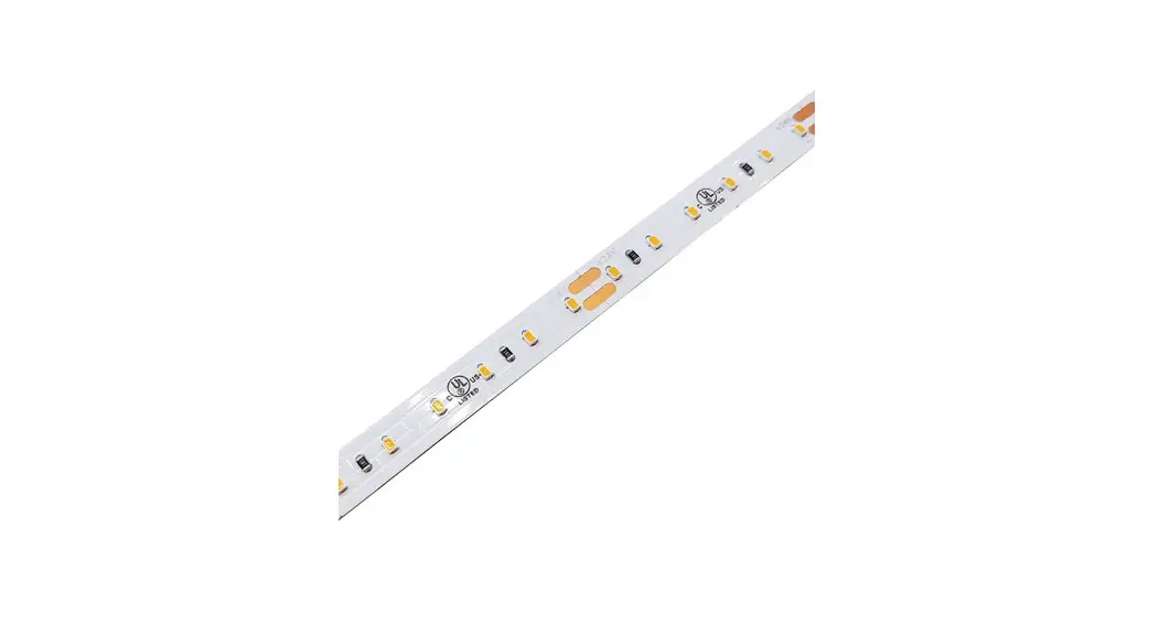
![]() KBM-D-H-SPI Kurba Medium Horizontal Flexible LED Strip
KBM-D-H-SPI Kurba Medium Horizontal Flexible LED Strip
Instruction Manual
7777 Merrimac Ave
Niles, IL 60714
T 224.333.6033
F 224.757.7557
[email protected]
www.luminii.com
Please read all instructions prior to installation and keep for future reference!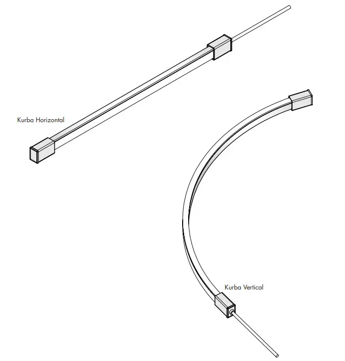
*LUMINII RESERVES THE RIGHT TO CHANGE SPECIFICATION & INSTRUCTION WITHOUT NOTICE
Please read all instructions prior to installation and keep them for future reference!
- PRODUCT TO BE INSTALLED BY A QUALIFIED ELECTRICIAN.
- USE ONLY WITH CLASS 2 POWER UNIT
- 24 VOLTS DC
- SUITABLE FOR WET LOCATIONS
- SURFACE MOUNT ONLY
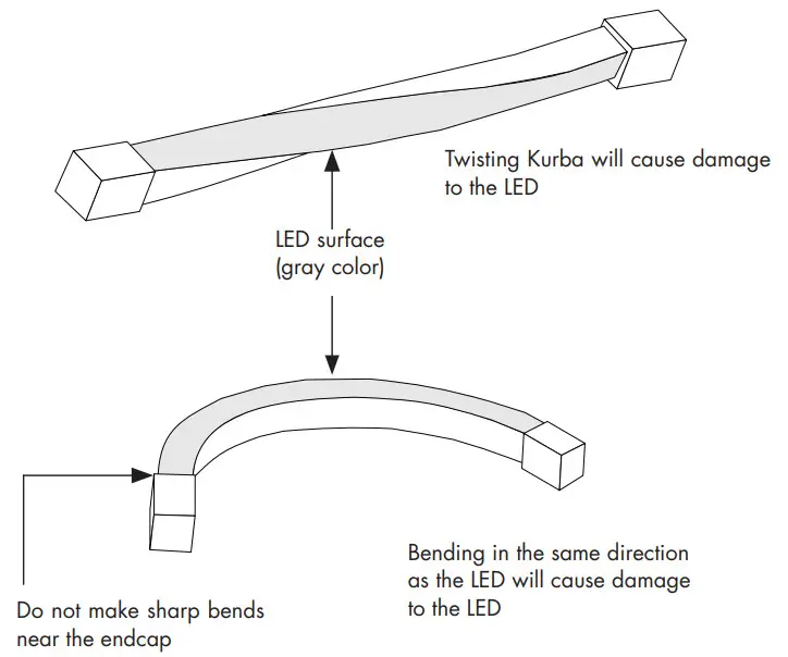
CAUTION: Reference diagram below on Can and Can-not, when it comes to installing the Kurba horizontal & Vertical!
Kurba Horizontal (KBM-XX)
CAN
Bend LED in these positions to avoid damage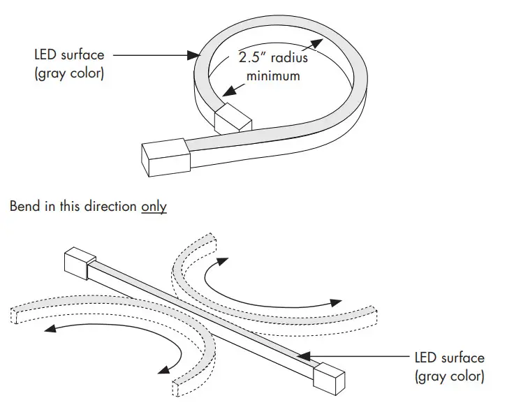 CAN NOT
Twisting or bending LED in these positions will cause damage to the LED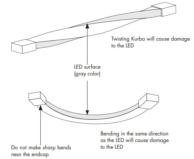 CAN
CAN
Bend LED in these positions to avoid damage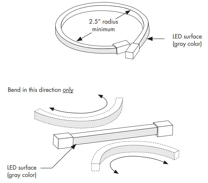
CAN NOT
Twisting or bending LED in these positions will cause damage to the LED
Installation Instructions – Kurba Pixel
NOTE: Prior to installation all 24VDC wires must be present within 72” of the installation. Refer to the power supply installation instruction for additional information.
NOTE: More than one person is recommended for this installation.
Once the location or pattern is determined for Kurba to be installed, start off by marking the area. The number of brackets may vary depending upon the pattern. Reference diagrams are below.
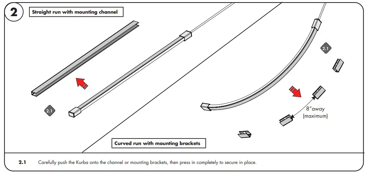
Straight run with mounting channel
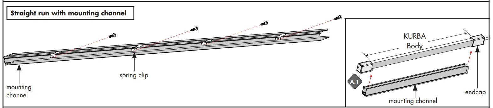
A.1 Line up the spring clips to the mounting holes, followed by placing the mounting channel to the surface. Make sure it’s straight by using a level.
A.2 Secure the channel to the surface by tightening all the provided screws. If mounting to something other than wood, we recommend using the proper hardware.
Curved run with mounting channel
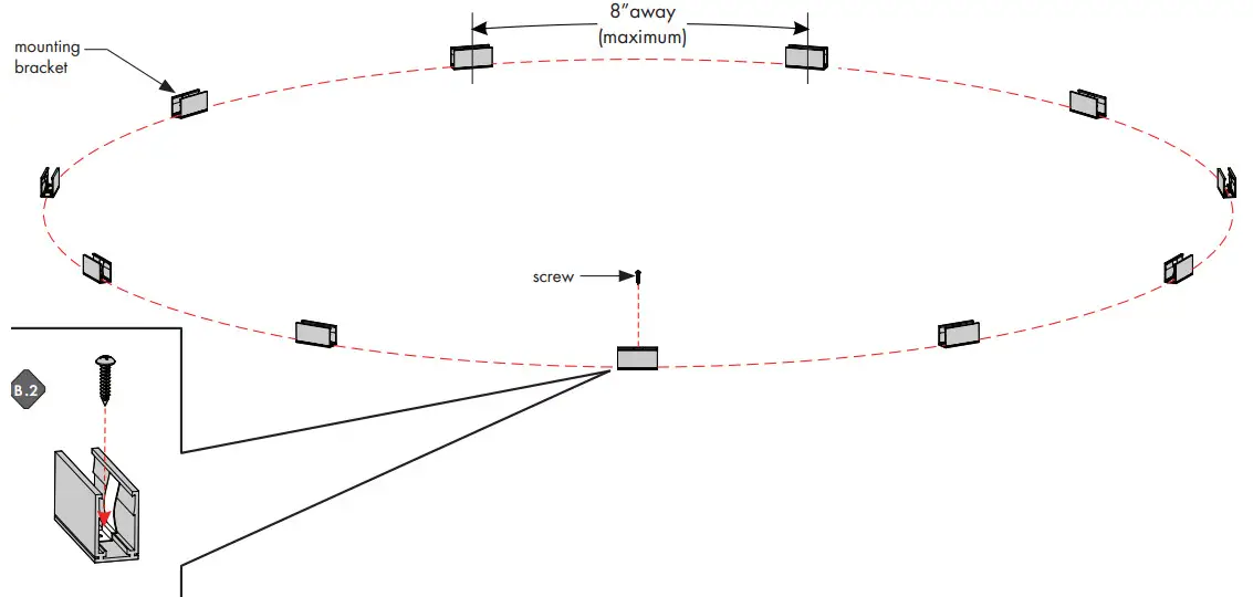
B.1 Determine the shape of the Kuba layout, then mark the pattern onto the surface. Then, place a mounting bracket every 8”(minimum).
The pattern may vary depending on the number of curves.
B.2 Secure the mounting brackets to the surface by tightening the screw. If mounting to something other than wood, we recommend using the proper hardware.
Please read all instructions prior to installation and keep for future reference!
WIRING DIAGRAM
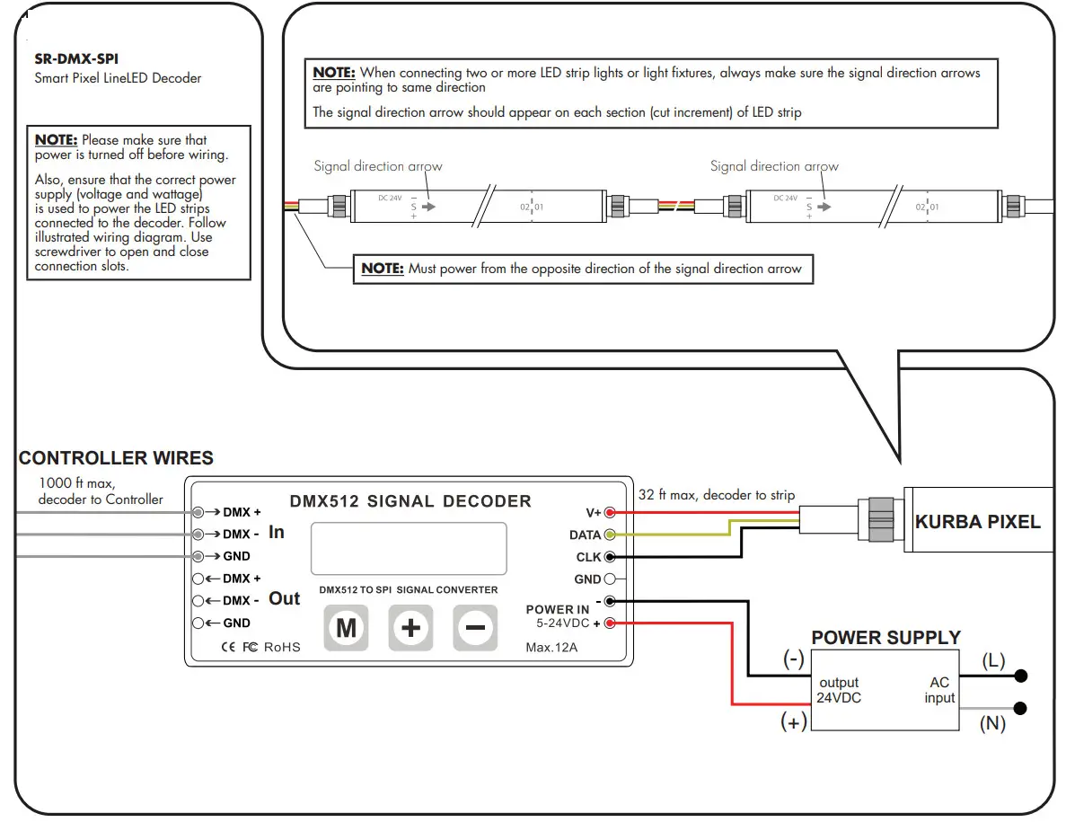
SR-DMX-SPI
Smart Pixel LineLED Decoder
NOTE: Please make sure that power is turned off before wiring.
Also, ensure that the correct power supply (voltage and wattage) is used to power the LED strips connected to the decoder. Follow illustrated wiring diagram. Use a screwdriver to open and close connection slots.
OPERATING GUIDE
SR-DMX-SPI
Smart Pixel LineLED Decoder
There are three buttons on the decoder.
![]()
After the operation, if no action was taken within the 30s, the button lock, and backlight of the screen will turn off.
- Long press the M button for 5s to unlock the buttons, and the backlight will turn on.
- Long press the M button for 5s to switch between test mode and decode mode after unlocked.
During test mode, the first line of LCD will show TEST MODE. Use test mode to verify RGBW Pixel functionality.
During decoder mode, the first line of LCD shows DECODER MODE. Use decoder mode when connecting to a
Controller and for final installation and customization.
The second line of the LCD Display shows the current setting and value. Note: 1 Pixel = 1 Cut Increment
NOTE:
When connected to a controller, DMX512 Signal Decoder will stay in “Decoder Mode”.
The second line of the LCD Display shows the current setting and value. Note: 1 Pixel = 1 Cut Increment
MODE TABLE
| SETTING | LCD DISPLAY | VALUE RANGE | DESCRIPTION |
| Built-in Programs | TEST MODE MODEL NO.: | 1-26 | See the Program Table below |
| Program Speed | TEST MODE RUN SPEED: | 7 | 0: fast, 7: slow |
| DMX Address | DECODER MODE DMX ADDRESS: | 1-512 | Address of the starting point/Pixel of a program |
| DMX Signal RGB | DECODER MODE DMX RGB SEQ: | RGB, BGR, etc. | N/A |
| Pixel Quantity | DECODER MODE PIXEL QTY: | 1-170(RGB), 1-128(RGBW) | Number of Pixels to follow a program |
| IC TYPE | DECODER MODE IC TYPE: | 2903, 8903, 2904, 8904 | 2903: N/A, 2904: for RGBW, 8903: N/A, 8904: N/A |
| Color | DECODER MODE COLOR: | MONO, DUAL, RGB, RGBW | MONO: N/A, DUAL: N/A, RGB: N/A, RGBW: for RGBW |
| Pixel Merging / Pixel Size | DECODER MODE PIXEL MERGE: | 1-100 | Number of Pixels to merge together |
| RGB Sequence | DECODER MODE LED RGB SEQ: | RGBW, BGRW, etc. | The sequence of RGBW, 24 possible combinations |
| Integral Control | DECODER MODE ALL CONTROL: | YES, NO | Yes: Merge all Pixels No: Maintain individual Pixels or Merged Pixels |
| Reverse Control | DECODER MODE REV-CONTROL: | YES, NO | Reverse program order |
| Overall Brightness | DECODER MODE BRIGHTNESS: | 1-100 | 1: dimmest setting 100: brightest setting |
NOTE:
When connected to a controller, DMX512 Signal Decoder will stay in “Decoder Mode”.
NOTE:
The actual maximum control pixels of the controller is 1360 (2903), and 1024 (2904). Please set the pixel and pixel combination value according to the actual situation, and DO NOT exceed the maximum.
NOTE: For Program Table
Change: no fading/dimming between color changes
Fade: fade/dim between color changes
Chase: change pixel by pixel
Chase with Trail: change pixel by pixel with fading between
PROGRAM TABLE
| PROGRAM NO. | PROGRAM DESCRIPTION |
| 1 | Solid color: Red |
| 2 | Solid color: Green |
| 3 | Solid color: Blue |
| 4 | Solid color: Yellow |
| 5 | Solid color: Purple |
| 6 | Solid color: Cyan |
| 7 | Solid color: White |
| 8 | RGB change |
| 9 | Full-color change |
| 10 | RGB fading |
| 11 | Full-color fading |
| 12 | Red chase with trail |
| 13 | Green chase with trail |
| 14 | Blue chase with trail |
| 15 | White chase with trail |
| 16 | RGB chase with trail |
| 17 | Rainbow chase with trail |
| 18 | RGB chasing and fading |
| 19 | Red chasing green, chasing blue |
| 20 | Orange chasing purple, chasing cyan |
| 21 | Rainbow chase (7 colors) |
| 22 | Random twinkle: white over red |
| 23 | Random twinkle: white over green |
| 24 | Random twinkle: white over blue |
| 25 | White fading |
| 26 | Off |
*LUMINII RESERVES THE RIGHTS TO CHANGE SPECIFICATION & INSTRUCTION WITHOUT NOTICE


