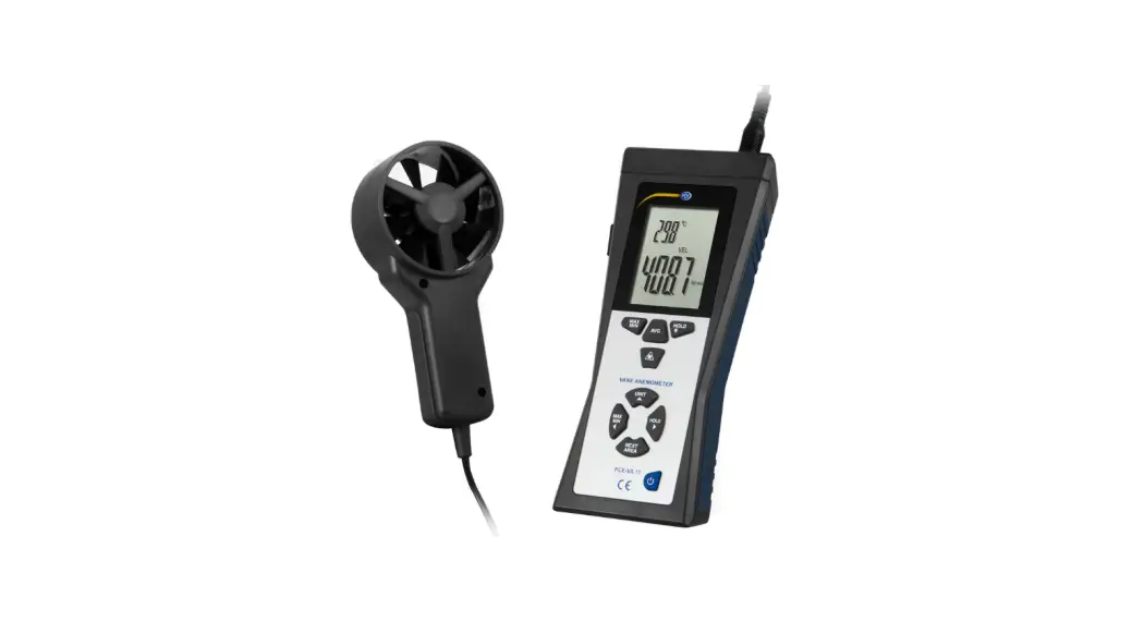
![]() Instruments PCE-VA 11 Thermo Anemometer
Instruments PCE-VA 11 Thermo Anemometer
User Manual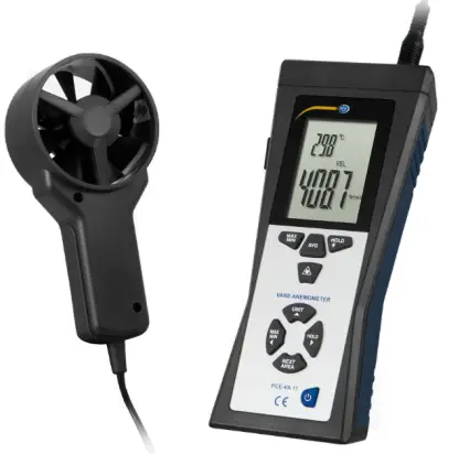
Safety notes
Please read this manual carefully and completely before you use the device for the first time.
The device may only be used by qualified personnel and repaired by PCE Instruments personnel. Damage or injuries caused by non-observance of the manual are excluded from our liability and not covered by our warranty.
- The device must only be used as described in this instruction manual. If used otherwise, this can cause dangerous situations for the user and damage to the meter.
- The instrument may only be used if the environmental conditions (temperature, relative humidity, …) are within the ranges stated in the technical specifications. Do not expose the device to extreme temperatures, direct sunlight, extreme humidity or moisture.
- Do not expose the device to shocks or strong vibrations.
- The case should only be opened by qualified PCE Instruments personnel.
- Never use the instrument when your hands are wet.
- You must not make any technical changes to the device.
- The appliance should only be cleaned with a damp cloth. Use only pH-neutral cleaner, no abrasives or solvents.
- The device must only be used with accessories from PCE Instruments or equivalent.
- Before each use, inspect the case for visible damage. If any damage is visible, do not use the device.
- Do not use the instrument in explosive atmospheres.
- The measurement range as stated in the specifications must not be exceeded under any circumstances.
- Non-observance of the safety notes can cause damage to the device and injuries to the user.
- Never point the laser beam at people or animals.
- Never look into the laser beam.
We do not assume liability for printing errors or any other mistakes in this manual.
We expressly point to our general guarantee terms which can be found in our general terms of business.
If you have any questions please contact PCE Instruments. The contact details can be found at the end of this manual.
Safety symbols
Safety-related instructions the non-observance of which can cause damage to the device or personal injury carry a safety symbol.
| Symbol | Designation / description |
 | Warning: laser beam Non-observance can cause injuries to the eyes. |
Specifications
2.1 Technical specifications
Air velocity
| Unit | Measuring range | Resolution | Accuracy |
| m/s | 0.40 … 30.00 | 0.01 | ±3 % ±0.20 m/s |
| ft/min | 80 … 5900 | 1 | ±3 % ±40 ft/min |
| km/h | 1.4 … 108.0 | 0.1 | ±3 % ±0.8 km/h |
| MPH | 0.9 … 67.0 | 0.1 | ±3 % ±0.4 MPH |
| Knots | 0.8 … 58.0 | 0.1 | ±3 % ±0.4 knots |
Air flow
| Unit | Measuring range | Resolution | Area |
| CFM | 0 … 9999 | 0.001 | 0 … 999.9 ft² |
| CMM | 0 … 9999 | 0.001 | 0 … 999.9 m² |
Air temperature
| Unit | Measuring range | Resolution | Area |
| °F | -58 … -4 °F | 0.1 °F | ±9.0 °F |
| °F | -4 … 932 °F | 0.1 °F | ±2 % of reading or ±4 °F |
| °C | -50 … -20 °C | 0.1 °C | ±5.0 °C |
| °C | -20 … 500 °C | 0.1 °C | ±2 % of reading or ±2 °F |
Infrared temperature
| Einheit | Messbereich | Auflösung | Genauigkeit |
| °F | -58 … -4 °F | 0,1 °F | ±9,0 °F |
| °F | -4 … 932 °F | 0,1 °F | ±2 % v. MW. oder ±4 °F |
| °C | -50 … -20 °C | 0,1 °C | ±5,0 °C |
| °C | -20 … 500 °C | 0,1 °C | ±2 % v. MW oder ±2 °F |
CFM (ft³/min) = air velocity (ft/min) x cross-section area (ft²)
CMM (ft³/min) = air velocity (m/s) x cross-section area (m²) x 60
CFM : cubic feet per minute
CMM: cubic meters per minute
General specifications
| Diameter vane probe | 72 mm 2.83 ” |
| Functions | MAX, MIN, AVG, HOLD |
| Memory | 8 cross-section areas 20 points average |
| Power supply | 9 V battery |
| Dimensions | 206 x 95 x 45 mm |
| Weight | 313 g |
2.2 Delivery contents
1 x thermo anemometer PCE-VA 11
1 x vane probe
1 x 9 V battery
1 x USB cable
1 x software
1 x carrying case
The free software can be downloaded here: https://www.pce-instruments.com/english/download-win_4.htm
System description
3.1 Device
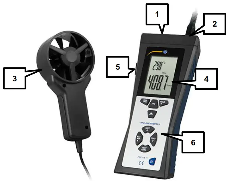
- Infrared sensor
- Vane probe connector
- Vane probe with air temperature sensor
- Display
- USB interface
- Control panel
3.2 Interfaces
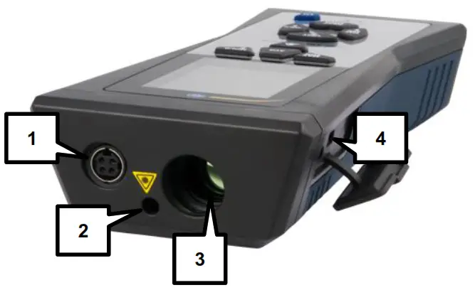
- Vane probe connector
- Laser pointer for aiming
- Infrared sensor
- USB interface
3.3 Display
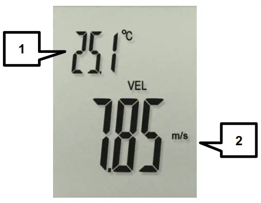
- Display for air temperature
- Display for air velocity, air flow and IR temperature
3.4 Function keys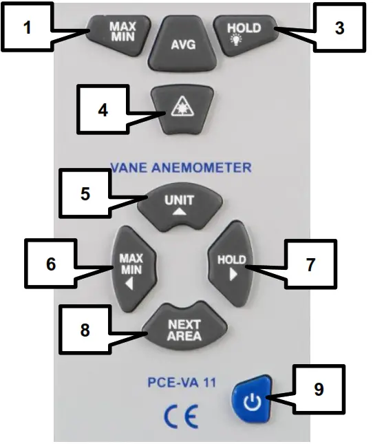
| No. | Key | Function |
| 1 | MAX/MIN (temperature) | • Press the key to view the maximum or minimum value of the air temperature. Press and hold the key to exit this mode. |
| 2 | AVG | • Press and hold the key to change to AVG mode, where the device calculates the average value of up to 20 single point measurements. • Press the key to watch the average value in measuring mode. |
| 3 | HOLD | • Press the key to freeze the current air temperature reading on the upper display. Press the key again to unfreeze the upper display. • Press and hold the key to turn the display backlight on/off. |
| 4 |  | • Press and hold the key to measure the temperature with the infrared sensor. |
| 5 | UNIT ▲ | • Press the key to change the mode and the measuring unit of the lower display. In FLOW mode, the device measures the air flow. In VEL mode, the device measures the air velocity. |
| • Press and hold the key to change the measuring unit on the upper display. • In AREA mode, press the key to increase the selected figure by 1. | ||
| 6 | MAX/MIN ◄ | • Press the key to view the maximum, minimum or average value. Press and hold the key to exit this mode. • In AREA mode, press the key to move the decimal point. |
| 7 | HOLD ► | • Press the key to freeze the current value on the lower display. Press the key again to unfreeze the lower display. • In AREA mode, press the key to move to the next digit. |
| 8 | NEXT AREA | • Press and hold the key to go to AREA mode, where you can set the cross-section area. Press and hold the key again to leave AREA mode. • In AREA mode, press the key to go to the next area. |
| 9 | • Press the key to turn the device on/off. |
Getting started
4.1 Power supply
When the![]() indication appears on the display, you need to change the battery. To do so, open the battery compartment on the back of the device by using a screwdriver and replace the 9 V battery. Close the battery compartment afterwards.
indication appears on the display, you need to change the battery. To do so, open the battery compartment on the back of the device by using a screwdriver and replace the 9 V battery. Close the battery compartment afterwards.
The device shuts down automatically after an idling time of 15 minutes. This function is deactivated in air flow mode (CFM, CMM) and average mode (AVG).
Operation
5.1 Measurement
5.1.1 Air velocity and air flow
- Press the
 key to turn on the device. It performs a quick self-test during which all display indications flash. After this, it goes to measuring mode.
In measuring mode, the upper display shows the air temperature while the lower display shows the air velocity or air flow. - By pressing the UNIT ▲ key, you can switch between the different measuring units, as well as between air velocity and air flow measurement. You can see which measuring mode (air velocity or air flow) is active by looking at the indications on the display. If air velocity mode is active, the display shows “VEL”. If air flow mode is active, the display shows “FLOW”.
5.1.2 Infrared temperature
Press and hold the![]() key to measure the surface temperature of an object with the infrared sensor. To help you with aiming at the object, the device has a built-in laser pointer which is active when the key is pressed. ATTENTION! Make sure to avoid eye contact with the laser beam!
key to measure the surface temperature of an object with the infrared sensor. To help you with aiming at the object, the device has a built-in laser pointer which is active when the key is pressed. ATTENTION! Make sure to avoid eye contact with the laser beam!
The surface temperature is shown on the lower display. During IR temperature measuring, all other display indications are deactivated.
To leave IR mode, just release the![]() key.
key.
5.2 Further functions
5.2.1 MAX/MIN and continuous AVG
MAX/MIN value
You can view the maximum or minimum value of the air velocity or air flow at any time. To do so, follow these steps:
- Turn on the device.
- Place the vane probe in front of the air flow source.
- Press the MAX/MIN ◄ key until “REC” and “MAX” or respectively “MIN” appears on the bottom of the display.
- The lower display now shows the maximum/minimum value since the activation of this mode.
Continuous average value
The device is able to calculate the average value of the air velocity or air flow over a period of up to 10 hours. To use this function, follow these steps:
- Turn on the device.
- Place the vane probe in front of the air flow source.
- Press the MAX/MIN ◄ key until “REC” and “AVG” appear on the display.
- The device now shows the continuous average value on the lower display. The value is updated every second.
Pause and stop the recording
To pause the recording and calculation of the MAX, MIN and AVG value, press the HOLD ► key. A HOLD indication appears on the bottom of the display. Now you can change the position of the vane probe and go to the next measuring point, for example.
To resume the recording, press the HOLD ► key again.
To exit MAX/MIN/AVG mode, press and hold the MAX/MIN ◄ key. The device beeps two times.
Now you can release the key and you get back to normal measuring mode.
5.2.2 Average value of multiple single point measurements
The device can calculate the average value of up to 20 single point measurements. To do so, follow these steps:
- Turn on the device.
- Press and hold the AVG key until the device beeps twice. Release the key and the display now shows “0” on the upper right side, as well as “AVG” on the bottom side.
- Place the vane probe in front of the air flow source.
- Wait for the reading and press the AVG key (the device beeps). The reading is saved and the device shows the average value and the number of measurements. The average value is displayed for about 3 seconds before the display switches back to the current reading. You can repeat this step for up to 20 measurements.
- To exit this mode, press and hold the AVG key until the device beeps twice. Now you are back in normal measuring mode.
To view the average value, press the AVG button. The display shows the AVG value and the number of measurements for 2 seconds.
5.2.3 MAX/MIN value of the air temperature
To view the maximum or minimum value of the air temperature, follow these steps:
- Press the MAX/MIN (temperature) key. “REC” and “MAX” or “MIN” appears on the top of the display.
- The upper display now shows the maximum or minimum value of the air temperature since the activation of this mode.
- To exit the mode, press and hold the MAX/MIN (temperature) key.
5.3 Settings
5.3.1 Area settings
In order to measure the air flow, you have to set the cross-section area first. To do so, follow these steps:
- Turn on the device.
- Press the UNIT ▲ key until CFM or CMM is selected as the active measuring unit.
- Press and hold the NEXT AREA key until the device beeps twice. An AREA indication appears on the right side of the display and a ft² or m² indication appears on the lower display.
- Press the MAX/MIN ◄ key to move the decimal point. Press the HOLD ► key to go to the next digit. Press the UNIT ▲ key to increase the selected figure by 1.
- Press the AREA key to go to the next cross-section area. You can store up to 8 different areas to the device.
- Press and hold the AREA key to confirm the settings and to take the selected crosssection area for the current measurement. The device returns to normal measuring mode.
5.4 Software
5.4.1 Installation
Device driver
- Download the latest version of the software from this website: https://www.pce-instruments.com/english/download-win_4.htm.
- Connect the device to your PC by using the supplied USB cable. A notification appears which asks you to install the “CP2102 USB to UART Bridge Controller”.
- Extract the downloaded zip file.
- Open the “USB Driver” folder.
- Start the “CP210xVCPInstaller_x64.exe” file if you run a 64 bit operating system or start the “CP210xVCPInstaller_x86.exe” file if you run a 32 bit operating system.
(If you are not sure which operating system is installed, right-click the computer icon on your desktop and select “Properties”. Now check “System type” to find out which operating system you use.)
Software
- Download the latest version of the software from this website: https://www.pce-instruments.com/english/download-win_4.htm.
- Connect the device to your PC by using the supplied USB cable. A notification appears which asks you to install the “CP2102 USB to UART Bridge Controller”.
- Extract the downloaded zip file.
- Execute “Setup.exe”.
- Follow the instructions on the screen.
5.4.2 Operation
Turn on the device, connect it to your PC and start the software. Now you see the main screen:
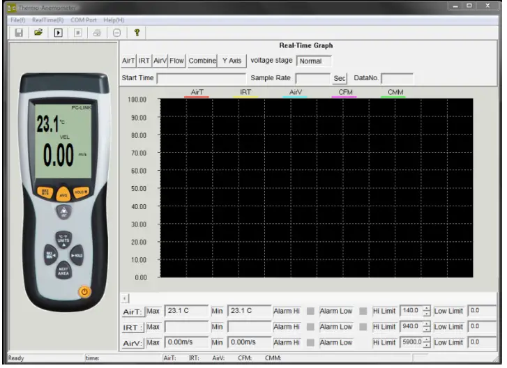
If the device is not identified by the software, make sure that the right COM port is selected. You can see the COM port of the device by checking your device manager (Windows Control Panel -> Device Manager).
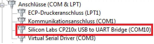
Click on “COM Port” in the menu bar of the software and select the proper COM port or click on “Other COM” and type it in.
Data logger
By using the PC software, you can use the device as a data logger as long as it is connected to the PC. To do so, follow these steps:
- Make sure that the device is turned on, connected to the PC and that the proper COM port is selected in the software.
- Click on the
 symbol or on “RealTime(R)” in the menu bar and select “Run”.
 - An input window appears where you can set the sampling time of the logger function. Type in the desired time in seconds and press “OK”.
- The data recording starts.
To stop the recording, click on the ![]() symbol or on „RealTime(R)” in the menu bar and select “Stop”.
symbol or on „RealTime(R)” in the menu bar and select “Stop”.
Setting alarm thresholds
You can use the software to set alarm thresholds. The settings are located below the graph:
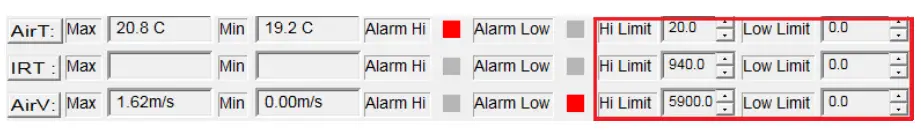
When the reading exceeds or falls below a set threshold level, the square next to “Alarm Hi”
respectively “Alarm Low” begins to flash.
Save Data
To save the recorded data, click on the ![]() symbol or click on “File(f)” in the menu bar and select “Save”. A save window appears where you can select the file name and the saving location.
symbol or click on “File(f)” in the menu bar and select “Save”. A save window appears where you can select the file name and the saving location.
The saved data can be viewed with the Windows Text Editor. The saved graphs can be viewed with the software.
Warranty
You can read our warranty terms in our General Business Terms which you can find here: https://www.pce-instruments.com/english/terms.
Disposal
For the disposal of batteries in the EU, the 2006/66/EC directive of the European Parliament applies. Due to the contained pollutants, batteries must not be disposed of as household waste.
They must be given to collection points designed for that purpose.
In order to comply with the EU directive 2012/19/EU we take our devices back. We either re-use them or give them to a recycling company which disposes of the devices in line with law.
For countries outside the EU, batteries and devices should be disposed of in accordance with your local waste regulations.
If you have any questions, please contact PCE Instruments.

PCE Instruments contact information
| Germany PCE Deutschland GmbH Im Langel 4 D-59872 Meschede Deutschland Tel.: +49 (0) 2903 976 99 0 Fax: +49 (0) 2903 976 99 29 [email protected] www.pce-instruments.com/deutsch United Kingdom PCE Instruments UK Ltd Unit 11 Southpoint Business Park Ensign Way, Southampton Hampshire United Kingdom, SO31 4RF Tel: +44 (0) 2380 98703 0 Fax: +44 (0) 2380 98703 9 [email protected] www.pce-instruments.com/english The Netherlands PCE Brookhuis B.V. Institutenweg 15 7521 PH Enschede Nederland Telefoon: +31 (0)53 737 01 92 [email protected] www.pce-instruments.com/dutch United States of America PCE Americas Inc. 711 Commerce Way suite 8 Jupiter / Palm Beach 33458 FL USA Tel: +1 (561) 320-9162 Fax: +1 (561) 320-9176 [email protected] www.pce-instruments.com/us | France PCE Instruments France EURL 23, rue de Strasbourg 67250 Soultz-Sous-Forets France Téléphone: +33 (0) 972 3537 17 Numéro de fax: +33 (0) 972 3537 18 [email protected] www.pce-instruments.com/french Italy PCE Italia s.r.l. Via Pesciatina 878 / B-Interno 6 55010 Loc. Gragnano Capannori (Lucca) Italia Telefono: +39 0583 975 114 Fax: +39 0583 974 824 [email protected] www.pce-instruments.com/italiano China PCE (Beijing) Technology Co., Limited 1519 Room, 6 Building Zhong Ang Times Plaza No. 9 Mentougou Road, Tou Gou District 102300 Beijing, China Tel: +86 (10) 8893 9660 [email protected] www.pce-instruments.cn | Spain PCE Ibérica S.L. Calle Mayor, 53 02500 Tobarra (Albacete) España Tel. : +34 967 543 548 Fax: +34 967 543 542 [email protected] www.pce-instruments.com/espanol Turkey PCE Teknik Cihazları Ltd.Şti. Halkalı Merkez Mah. Pehlivan Sok. No.6/C 34303 Küçükçekmece – İstanbul Türkiye Tel: 0212 471 11 47 Faks: 0212 705 53 93 [email protected] www.pce-instruments.com/turkish Hong Kong PCE Instruments HK Ltd. Unit J, 21/F., COS Centre 56 Tsun Yip Street Kwun Tong Kowloon, Hong Kong Tel: +852-301-84912 [email protected] www.pce-instruments.cn |
![]() User manuals in various languages
User manuals in various languages can be downloaded here: www.pce-instruments.com
Specifications are subject to change without notice.
© PCE Instruments
References
 France.fr : Actualités, destinations et infos du tourisme en France
-
iberica.es
-
instruments.cn
 Make an offer on the domain instruments.co.uk - Domains.co.uk
-
Computer Instruments | Home
 Discover Italy: Official Tourism Website - Italia.it
 PCE(北京)科技有限公司
-
Industrial Measurement Products and Solutions | PCE Instruments
-
PCE Deutschland GmbH Prüfgeräte vom Hersteller | PCE Instruments
-
PCE Brookhuis B.V. | PCE Instruments
-
PCE Americas Inc. : Test Instruments | PCE Instruments
-
PCE Iberica S.L. Instrumentación | PCE Instruments
-
PCE Instruments France | PCE Instruments
-
PCE Italia s.r.l. / Strumenti di Misura | PCE Instruments
-
PCE Teknik Cihazlar Paz. Tic. Ltd.Şti. | PCE Instruments
-
PCE Deutschland GmbH Prüfgeräte vom Hersteller | PCE Instruments
-
Download vom Hersteller | PCE Instruments
-
Download | PCE Instruments
-
PCE Americas Inc. : Test Instruments | PCE Instruments


