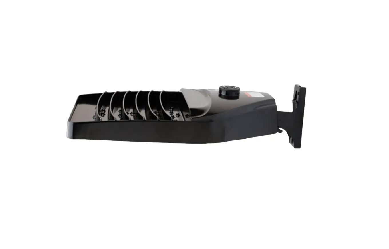
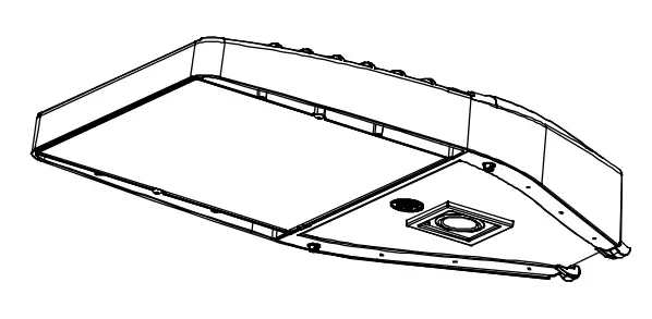
GE current Evolve EALS Series LED Outdoor Area Light
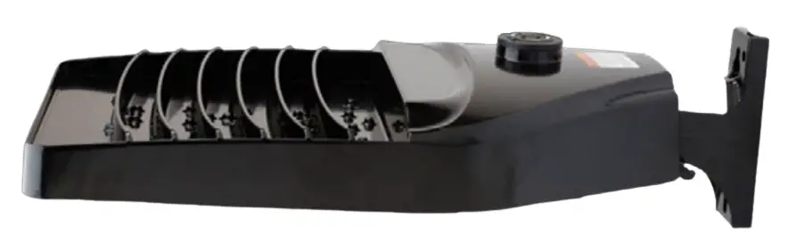
The EALS Area Light luminaire offers a wide range of optical patterns, color temperatures, lumen packages and mounting configurations to optimize area light applications, as well as provide versatility in lighting design within the same form-factor. They are ideal for commercial property site-lighting applications such as retail and commercial exteriors.
| Housing: Aluminum die cast enclosure. Integral heat sink for maximum heat transfer |
| Lens: Impact resistant tempered glass |
| Paint: Corrosion resistant polyester powder paint, minimum 2.0 mil thickness Standard = Black, Dark Bronze Gray, White (RAL & custom colors available) Optional = Coastal Finish |
| Weight: 27 lbs |
OPTICAL SYSTEM
| Lumens: 7,000 – 30,300 Photometry: Type II, III, IV & V |
| Efficacy: 126 – 160 LPW CCT: 3000K, 4000K, 5000K |
| CRI: ≥70 |
| Upward Light Output Ration (ULOR): 0 Horizontal Orientation |
ELECTRICAL
| Input Voltage: | 120-277V, 277-480V & 347-480V |
| Input Frequency: | 50/60 Hz |
| Power Factor (PH): | > 90% at rated watts |
| Total Harmonic Distortion (THD): | < 20% at rated watts |
SURGE PROTECTION
TYPICAL (120 STRIKES)
- 6kV/3kA*

- 10kV/5kA*
- 20kV/10kA*
*Per ANSI C136.2-2015
LUMEN MAINTENANCE
Projected Lxx per IES TM-21-11 at 25°C
| Optics | 25,000 HR | LXX(10K) @ Hours 50,000 HR | 60,000 HR |
| C2, C3, C4, C5, D2, D3, D4, D5 | L96 | L92 | L91 |
| F5, H2, H3, H4, H5 | L95 | L93 | L92 |
| F2, F3, F4, J3, J3, J4, J5 | L95 | L93 | L92 |
| K2, K3, K4, K5 | L95 | L93 | L92 |
Note: Projected Lxx based on LM80 (= 10,000 hour testing). Accepted Industry tolerances apply to initial luminous flux and lumen maintenance measurements
LUMINAIRE AMBIENT TEMPERATURE FACTOR
| Ambient Temp (°C) | Initial Flux Factor |
| 10 | 1.02 |
| 20 | 1.01 |
| 25 | 1.00 |
| Ambient Temp (°C) | Initial Flux Factor |
| 30 | 0.99 |
| 40 | 0.98 |
RATINGS
Operating Temperature: -40° C to 40° C
Vibration: 3G per ANSI C136.31-2010
LM-79: Testing in accordance with IESNA Standards
CONTROLS
Dimming: Standard – 0-10V  Optional – DALI (Option U) |
| Sensors: Photo Electric Sensors (PE) available LightGrid and Daintree Compatible |
WARRANTY
- 5 Year (Standard)
- 10 Year (Optional)

Catalog Logic
Ordering Information

| PRODUCT ID | GENERATION | VOLTAGE | OPTICAL CODE | DISTRIBUTION | CRI | CCT | DIMMING² | CONTROLS | MOUNTING ARM | COLOR | OPTIONS |
| E= Evolve | 03 | 01=120- 277 | Cx =7500 | SM = Symmetric Medium | 7 = 70 (min) | 3011 = 3000K | N¹³ = Dimming thru PE receptacle | 1 = None | C14 = Integral Slipfitter: Standard | BLCK = Black | F= Fusing |
| AL= Area Light | H1 = 347- 480V | Dx = 10000 | SW = Symmetric Wide | 40 = 4000K | D¹³ = External Dimming 18/2 3 ft Cable | A = ANSI C136.41 7-Pin Receptacle (No Control) | D15 = Universal Mounting Arm: Fitted for round or square pole mounting | DKBZ = Dark Bronze | H8 = Motion Sensor (Sensor Switch) | ||
| S = Standard | E1,9 = 277- 480 | Fx = n15000 | SH = Symmetric High Angle | 50 = 5000K | X¹⁴ = Non dimming, no external dimming leads | D = ANSI C136.417-Pin Receptacle with Shorting Cap | K14, 6 = Knuckle Slipfitter: For 1.9 in. – 2.3 in OD Tenon | GRAY = Gray | H1 = LightGrid w/ WattStopper | ||
| Hx = 20000 | AF = Asymmetric Forward | E3 = ANSI C136.41 7-pin with Non-Dimming PE Control | S14, 6 = Knuckle Slipfitter: For 2.3 in. – 3.0 in OD Tenon | WHTE = White | H28 = Daintree enabled motion sensor | ||||||
| 1 = 120 | Jx = 25000 | AH = Asymmetric High Angle | V14, 6 = Knuckle Wall Mount | H4 = Motion Sensor (WattStopper) | |||||||
| 2 = 208 | Kx = 30000 | AW = Asymmetric Wide | J = cUL/Canada | ||||||||
| 3 = 240 | AN = Asymmetric Narrow/Auto | L = Tool-Less Entry | |||||||||
| 4 =277 | R = Enhanced Surge Protection (10kV/5kA) | ||||||||||
| D = 347 | S1¹² = Rotated Left | ||||||||||
| 5 = 480 | S2¹² = Rotated Right | ||||||||||
| T = Extreme Surge Protection (20kV/10kA) | |||||||||||
| U 7, 8 = DALI Programmable | |||||||||||
| V = 3 Position Terminal Block | |||||||||||
| Y10 = Coastal Finish | |||||||||||
| XXX = Special Options |
¹ Not Available with Fusing, Must Choose a Discrete Voltage with “F” Option Code
² Note Standard Dimming is 0-10V
³ PE Control only available for 120-277V, 347V or 480V Discrete Voltage.
⁴ Supplied with 3ft leads
⁵ Supplied with 16/3 ft Cable
⁶ Restricted Aiming Angle of 0-45°
⁷ Compatible with LightGrid Wireless Control Nodes, Not Compatible with Motion Sensor Control
⁸ Not available in 347V, 480V or 347-480V
⁹ Only available with H, J & K optics
10 Recommended for installations within 750 feet from coast. Lead time varies, check with factory.
11 Select 3000K CCT for IDA approved fixtures.
¹² For aimed left of right light distribution orientation, as assembled in manufacturing. Not applicable for Symmetric Distributions
¹³ Can only be ordered with controls A, D, and E
¹⁴ Required for Cx optical codes only, not available for other optic codes
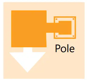
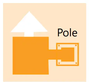
- Left (S1)

- Right (S2)
Spec Tables
| TYPE | OPTIC CODE | DISTRIBUTION | TYPICA L INITIAL LUMENS 3000K 4000K & 5000K | TYPICAL SYSTEM WATTAGE 120-277 & 347-480V | BUG RATINGS 3000K 4000 & 5000K B-U-G B-U-G | ||
|
TYPE V | C5 | Symmetric Medium (SM) | 7300 | 7500 | 46 | B3-U0-G1 | B3-U0-G1 |
| D5 | Symmetric Medium (SM) | 9800 | 10000 | 64 | B3-U0-G1 | B3-U0-G1 | |
| F5 | Symmetric Medium (SM) | 14700 | 15000 | 101 | B4-U0-G2 | B4-U0-G2 | |
| H5 | Symmetric Medium (SM) | 19600 | 20000 | 140 | B4-U0-G2 | B4-U0-G2 | |
| J5 | Symmetric Medium (SM) | 24500 | 25000 | 186 | B4-U0-G2 | B4-U0-G2 | |
| K5 | Symmetric Medium (SM) | 29400 | 30000 | 239 | B5-U0-G3 | B5-U0-G3 | |
| C5 | Symmetric Wide (SW) | 7300 | 7500 | 46 | B2-U0-G1 | B2-U0-G1 | |
| D5 | Symmetric Wide (SW) | 9800 | 10100 | 64 | B3-U0-G1 | B3-U0-G1 | |
| F5 | Symmetric Wide (SW) | 14700 | 15100 | 101 | B3-U0-G2 | B3-U0-G2 | |
| H5 | Symmetric Wide (SW) | 19700 | 20200 | 140 | B4-U0-G2 | B4-U0-G2 | |
| J5 | Symmetric Wide (SW) | 24600 | 25200 | 186 | B4-U0-G2 | B4-U0-G2 | |
| K5 | Symmetric Wide (SW) | 29600 | 30300 | 239 | B5-U0-G2 | B5-U0-G2 | |
| C5 | Symmetric High Angle (SH) | 7000 | 7200 | 46 | B3-U0-G1 | B3-U0-G1 | |
| D5 | Symmetric High Angle (SH) | 9400 | 9600 | 64 | B3-U0-G2 | B3-U0-G2 | |
| F5 | Symmetric High Angle (SH) | 14200 | 14500 | 101 | B4-U0-G2 | B4-U0-G2 | |
| H5 | Symmetric High Angle (SH) | 18900 | 19300 | 140 | B4-U0-G2 | B4-U0-G2 | |
| J5 | Symmetric High Angle (SH) | 23600 | 24100 | 186 | B5-U0-G3 | B5-U0-G3 | |
| K5 | Symmetric High Angle (SH) | 28400 | 29000 | 239 | B5-U0-G3 | B5-U0-G3 | |
|
TYPE IV | C4 | Asymmetric Forward (AF) | 7300 | 7500 | 50 | B1-U0-G2 | B1-U0-G2 |
| D4 | Asymmetric Forward (AF) | 9800 | 10000 | 70 | B2-U0-G2 | B2-U0-G2 | |
| F4 | Asymmetric Forward (AF) | 14700 | 15000 | 116 | B2-U0-G2 | B2-U0-G2 | |
| H4 | Asymmetric Forward (AF) | 19600 | 20000 | 140 | B3-U0-G3 | B3-U0-G3 | |
| J4 | Asymmetric Forward (AF) | 24500 | 25000 | 186 | B3-U0-G3 | B3-U0-G3 | |
| K4 | Asymmetric Forward (AF) | 29400 | 30000 | 239 | B3-U0-G4 | B3-U0-G4 | |
| C4 | Asymmetric High Angle (AH) | 7000 | 7200 | 50 | B2-U0-G2 | B2-U0-G2 | |
| D4 | Asymmetric High Angle (AH) | 9400 | 9600 | 70 | B2-U0-G2 | B2-U0-G2 | |
| F4 | Asymmetric High Angle (AH) | 14200 | 14500 | 116 | B3-U0-G3 | B3-U0-G3 | |
| H4 | Asymmetric High Angle (AH) | 18900 | 19300 | 140 | B3-U0-G3 | B3-U0-G4 | |
| J4 | Asymmetric High Angle (AH) | 23600 | 24100 | 186 | B3-U0-G4 | B3-U0-G4 | |
| K4 | Asymmetric High Angle (AH) | 28400 | 29000 | 239 | B3-U0-G4 | B3-U0-G4 | |
|
TYPE III | C3 | Asymmetric Wide (AW) | 7300 | 7500 | 50 | B2-U0-G1 | B2-U0-G1 |
| D3 | Asymmetric Wide (AW) | 8900 | 10100 | 70 | B2-U0-G2 | B2-U0-G2 | |
| F3 | Asymmetric Wide (AW) | 14700 | 15100 | 116 | B2-U0-G2 | B2-U0-G2 | |
| H3 | Asymmetric Wide (AW) | 19800 | 20200 | 140 | B3-U0-G2 | B3-U0-G3 | |
| J3 | Asymmetric Wide (AW) | 24600 | 25200 | 186 | B3-U0-G3 | B3-U0-G3 | |
| K3 | Asymmetric Wide (AW) | 29600 | 30300 | 239 | B3-U0-G3 | B3-U0-G3 | |
|
TYPE II | C2 | Asymmetric Narrow/Auto (AN) | 7300 | 7500 | 50 | B3-U0-G2 | B2-U0-G2 |
| D2 | Asymmetric Narrow/Auto (AN) | 9800 | 10100 | 70 | B2-U0-G2 | B2-U0-G2 | |
| F2 | Asymmetric Narrow/Auto (AN) | 14700 | 15100 | 116 | B2-U0-G2 | B3-U0-G3 | |
| H2 | Asymmetric Narrow/Auto (AN) | 19700 | 20200 | 140 | B3-U0-G3 | B3-U0-G3 | |
| J2 | Asymmetric Narrow/Auto (AN) | 24600 | 25200 | 186 | B3-U0-G3 | B3-U0-G3 | |
| K2 | Asymmetric Narrow/Auto (AN) | 29600 | 30300 | 239 | B3-U0-G3 | B3-U0-G3 | |
For additional information on EALS files, please click one of the following links:
Photometric Plots
EALS03
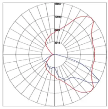
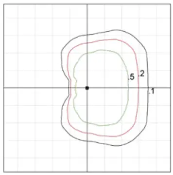
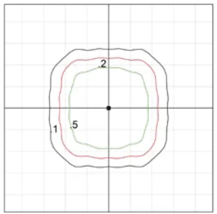
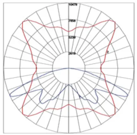
ASYMMETRIC NARROW (K2AN750)
30300 Lumens
5000k
EALS03_K2AN750________.IES
Gridline spacing is equal to mounting height. Initial footcandle values shown are at grade for 40’ mounting height
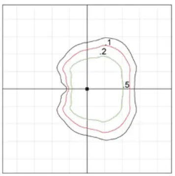
———- : Vertical plane through horizontal angle of maximum candlepower at 55°
———- : Vertical plane through horizontal angle 34°
EALS03
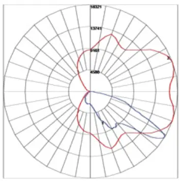
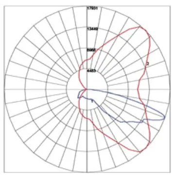
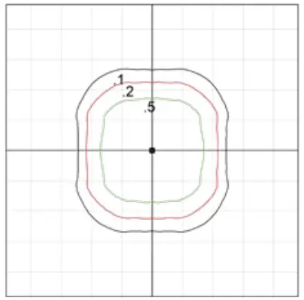
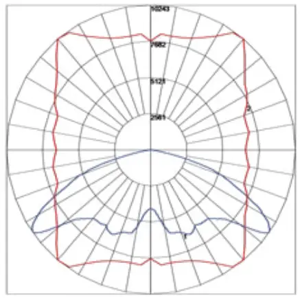
ASYMMETRIC WIDE (K3AW750)
30300 Lumens
5000k
EALS03_K3AW750________.IES
Gridline spacing is equal to mounting height. Initial footcandle values shown are at grade for 40’ mounting height.
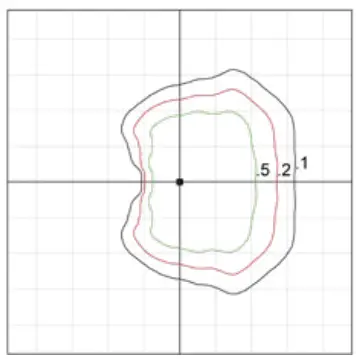
———- : Vertical plane through horizontal angle of maximum candlepower at 45°
———- : Vertical plane through horizontal angle 58°
EALS03
ASYMMETRIC HIGH ANGLE (K4AH750)
29000 Lumens
5000k
EALS03_K4AH750________.IES
Gridline spacing is equal to mounting height. Initial footcandle values shown are at grade for 40’ mounting height.
———- : Vertical plane through horizontal angle of maximum candlepower at 45°
———- : Vertical plane through horizontal angle 70
EALS03
SYMMETRIC HIGH ANGLE (K5SH750)
29000 Lumens
5000k
EALS03_K5SH750________.IES
Gridline spacing is equal to mounting height. Initial footcandle values shown are at grade for 40’ mounting height.
———- : Vertical plane through horizontal angle of maximum candlepower at 50°
———- : Vertical plane through horizontal angle 69°
EALS03
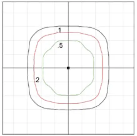
SYMMETRIC MEDIUM (K5SM750)
30000 Lumens
5000k
EALS03_K5SM750________.IES
Gridline spacing is equal to mounting height. Initial footcandle values shown are at grade for 40’ mounting height.
———- : Vertical plane through horizontal angle of maximum candlepower at 45°
———- : Vertical plane through horizontal angle 65°
EALS03
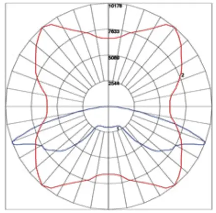
SYMMETRIC WIDE (K5SW750)
30300 Lumens
5000k
EALS03_K5SW750________.IES
Gridline spacing is equal to mounting height. Initial footcandle values shown are at grade for 40’ mounting height.
———- : Vertical plane through horizontal angle of maximum candlepower at 50°
———- : Vertical plane through horizontal angle 55°
Motion Sensing
H-MOTION SENSING OPTION
- Recommended Mounting Height: 15-30’ (4.6-9.1m)
- For mounting heights exceeding 30 ft., pole mounted sensors are recommended
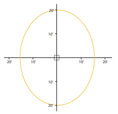
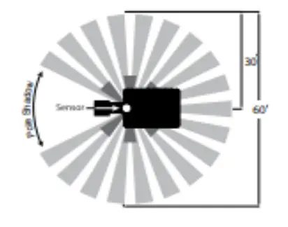
- Coverage Radius: 15-20’ (4.6-6.1 m).
- Provides 270 degree of coverage (approx 90 is blocked by the pole)
- Default Settings:
– Output: Occupied – 100%/Unoccupied – 50%
– Integral PE Sensor.
– 5 minute post-occupancy time delay, 5 minute dimming rampdown. - Fixture power increase of 1W expected with sensor use.

H1/4 – MOTION SENSING OPTION (WATTSTOPPER)
- Recommended Mounting Height: 15-30’ (4.6-9.1m)
- For mounting heights exceeding 30 ft., pole mounted sensors are recommended
- SIDE VIEWCoverage Radius: 15-20’ (4.6-6.1 m).
- Provides 270 degree of coverage (approx 90 is blocked by the pole)
- Default Settings:
– Output: Occupied – 100%/Unoccupied – 50%
– PE Sensor: Enabled
– Ramp/Fade: 5 Minutes/5 Minutes - Adds < 1W to fixture power rating
- Field programmable using FSIR-100 hand held programmer

H2 – MOTION SENSING OPTION (DAINTREE)
- Recommended Mounting Height: 15-30’ (4.6-9.1m)
- For mounting heights exceeding 30 ft., pole mounted sensors are recommended
- Provides a coverage area radius for walking motion of 15-20 ft. (4.57-6.10m)
- Provides 270 degree of coverage (approx 90 is blocked by the pole)
- Default Settings:
– Output: Occupied – 100%/Unoccupied – 50%
– PE Sensor: None
– Ramp/Fade: 5 Minutes/5 Minutes - Adds < 1W to fixture power rating
- Requires Daintree Enterprise and wide area control (WAC)
Sensing Pattern Area Fixture Up to 30 ft. Mounting Height
Mounting & Accessories
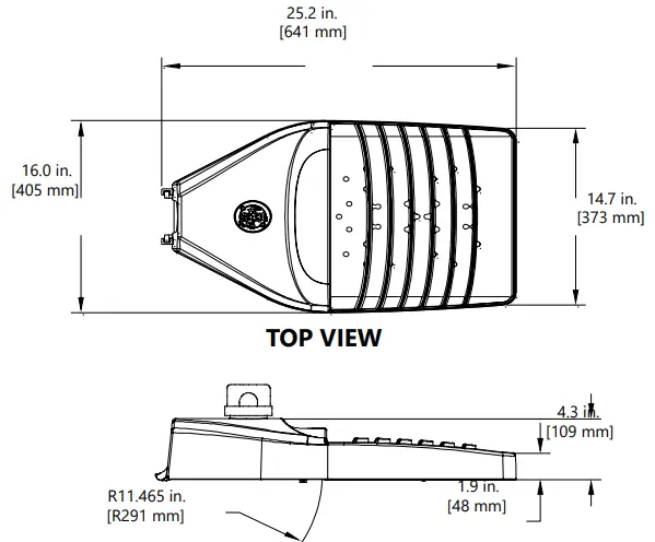
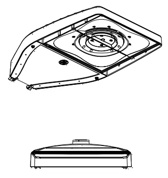
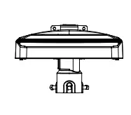
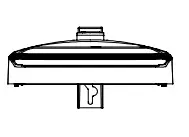
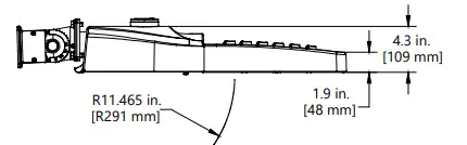
INTEGRAL SLIPFITTER: C1
- TOP VIEW / SIDE VIEW

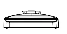
- FRONT VIEW

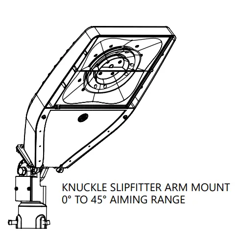
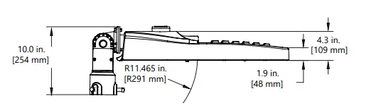
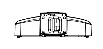
KNUCKLE SLIPFITTER: S1
TOP VIEW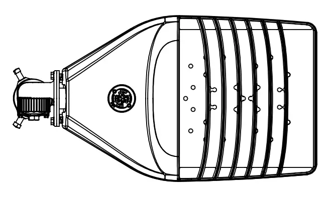
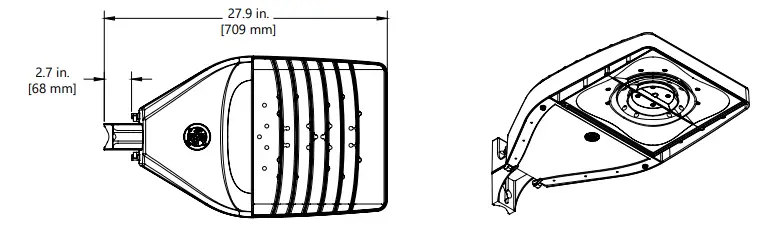
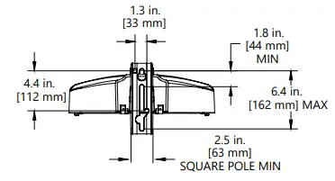
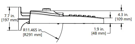
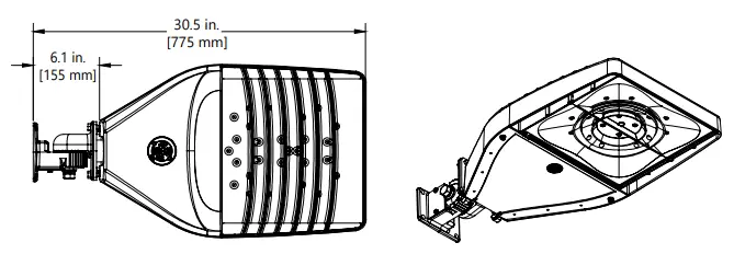
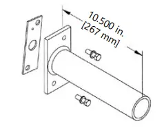
UNIVERSAL ARM MOUNT: D1
- TOP VIEW

- BACK VIEW

- SIDE VIEW

- FRONT VIEW

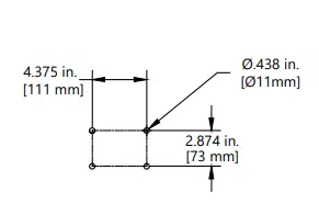
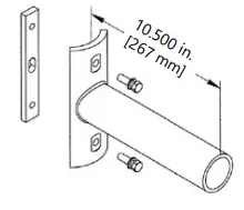
KNUCKLE WALL MOUNT: V1
- TOP VIEW

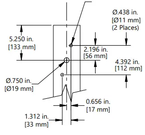
- Wall Mount Hole Pattern

- BACK VIEW

- SIDE VIEW

- FRONT VIEW

DATA
- Approximate Net Weight: 26-28 lbs (11.79 kgs-12.97 kgs)
- Effective Projected Area (EPA):
- Knuckle Slipfitter S1, 45° aim, EPA = 2.45
- Knuckle w/Slipfitter S1, downward aim, EPA = 0.73
- Universal Arm Mount D1, EPA = 0.54
- Knuckle Wall Mount V1, 45° aim, EPA = 0.77 sq ft min and 1.43 sq ft max
- Integral Slipfitter C1, EPA = 0.63
MOUNTING ARMS FOR SLIPFITTER
Order separately with Mounting Option C1 (Slipfitter)
SQUARE POLE MOUNTING ARM
3.5 TO 4.5-inch (89 to 114mm) SQUARE (WILL ALLOW 4 FIXTURES PER POLE @ 90 DEGREES.)
ORDER SEPARATELY FROM FIXTURE AS CATALOG NUMBER
SPA-EAMT10BLCK “Black”
SPA-EAMT10DKBZ “Dark Bronze”
SQUARE POLE MOUNTING DRILLING TEMPLATE
ROUND POLE MOUNTING ARM DRILLING TEMPLATE
3.5 TO 4.5-inch (89 to 114mm) OD (WILL ALLOW 4 FIXTURES PER POLE @ 90 DEGREES.)
ORDER SEPARATELY FROM FIXTURE AS CATALOG NUMBER
RPA-EAMT10BLCK “Black”
RPA-EAMT10DKBZ “Dark Bronze”
ROUND POLE MOUNTING DRILLING TEMPLATE
3.5 TO 4.5-inch (89 to 114mm) OD round pole mounting arm
Wall Mounting Bracket Adapter Plate
ORDER SEPARATELY FROM FIXTURE AS CATALOG NUMBER
WMB-EAMT06
*NOTE: For Wall Mounting, order luminaire with mounting arm: C1 = Slipfitter 2″ Pipe (2.378 in. OD) supplied with leads.
Other mounting patterns are available for retrofit installations. Contact manufacturing for other available mounting patterns.
| SAP NUMBER | PART NUMBER | DESCRIPTION | SAP NUMBER | PART NUMBER | DESCRIPTION |
| 93123552 | WANSI – 277 | ANSI 136.41 Dimming PE Daintree Enable, 105-305V | 28299 | PECOTL | Standard 120-277V |
| 93123553 | WANSI – 480 | ANSI 136.41 Dimming PE Daintree Enable, 312-530V | 28294 | PEC5TL | Standard 480V |
| 93029237 | PED-MV-LED-7 | ANSI C136.41 Dimming PE, 120-277V | 80436 | PECDTL | Standard 347V |
| 93029238 | PED-347-LED-7 | ANSI C136.41 Dimming PE, 347V | 93147530 | PECHTL | Long Life Standard PE, 347-480V |
| 93029239 | PED-480-LED-7 | ANSI C136.41 Dimming PE, 480V | 73251 | SCCL-PECTL | Shorting Cap |
www.gecurrent.com
© 2022 Current Lighting Solutions, LLC. All rights reserved. GE and the GE monogram are trademarks of the General Electric Company and are used under license. Information
provided is subject to change without notice. All values are design or typical values when measured under laboratory conditions.
OLP3111 (Rev 3/4/22)