![]()
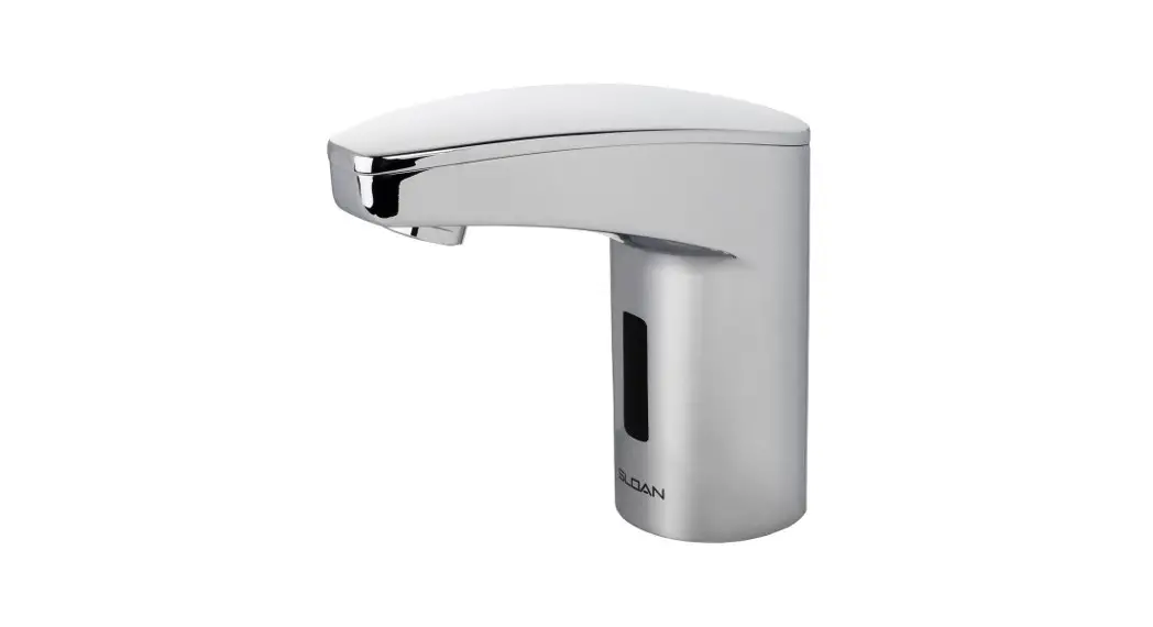
INSTALLATION INSTRUCTIONS FOR EAF-350 SERIES ELECTRONIC,
BATTERY-POWERED, SENSOR-ACTIVATED LAVATORY FAUCETS
Faucet Variations
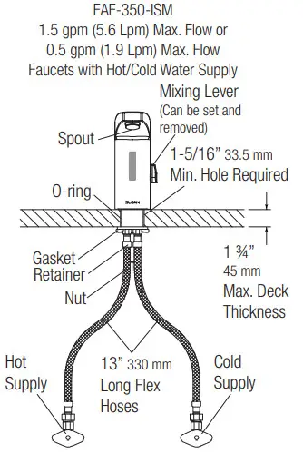
-ISM
Integral Spout Temperature Mixer

Limited Warranty
Unless otherwise noted, Sloan Valve Company warrants its products, manufactured and sold for commercial or industrial uses, to be free from defects of material and workmanship for a period of three (3) years (one (1) year for SF faucets, special finish and PWT electronics and 30 days on PWT software) from the date of first purchase. During this period, Sloan Valve Company will, at its option, repair, replace, or refund the purchase price of any product which fails to conform with this warranty under normal use and service. This shall be the sole and exclusive remedy under this warranty. Products must be returned to Sloan Valve Company, at the customer’s cost. No claims will be allowed for labor, transportation or other costs. This warranty extends only to persons or organizations that purchase
Sloan Valve Company’s products are directly from Sloan Valve Company for purpose of resale. This warranty does not cover the life of batteries.
THERE ARE NO WARRANTIES THAT EXTEND BEYOND THE DESCRIPTION ON THE FACE HEREOF. IN NO EVENT IS SLOAN VALVE COMPANY RESPONSIBLE FOR ANY CONSEQUENTIAL DAMAGES OF ANY MEASURE WHATSOEVER.
PRIOR TO INSTALLATION
Prior to installing the Sloan OPTIMA Plus® EAF-350 Series faucets, install the items listed below. Also, refer to rough-in illustrations.
- Lavatory/sink
- Drain line
- Hot/Cold water supply lines or pre-tempered water supply line
IMPORTANT:
- ALL PLUMBING SHOULD BE INSTALLED IN ACCORDANCE WITH APPLICABLE CODES AND REGULATIONS.
- FLUSH ALL WATER LINES PRIOR TO MAKING CONNECTIONS.
- KEEP THREAD SEALANT OUT OF YOUR WATERWAY TO PREVENT COMPONENT PART DAMAGE! DO NOT USE ANY SEALANT ON COMPRESSION FITTINGS.
Trim Plates
When the EAF faucet is installed on a sink that has three (3) hole punching, a trim plate should be used. Trim plates must be specifi ed and ordered separately.
ETF-312-A Trim Plate for 4” (102 mm) Centerset Sink
ETF-510-A Trim Plate for 8” (203 mm) Centerset Sink
Tools Required for Installation
- 13mm open wrench or nut driver for faucet retainer nut
- 3/4” open-end wrench for female end of flex hose
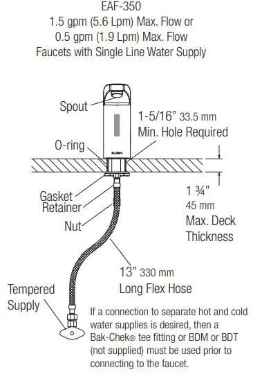
FAUCET ROUGH-IN

Side View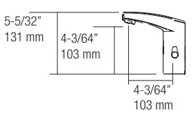
Front View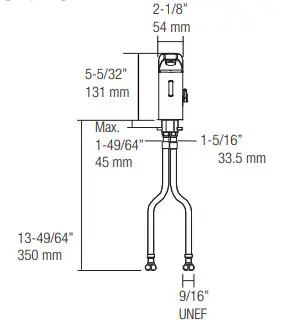
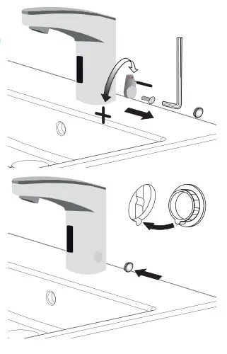
INSTALL FAUCET
A.Remove nut, faucet retainer, and gasket. DO NOT remove the o-ring from the base of the faucet.
DO NOT remove sensor label until step.4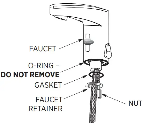
B.Install faucet with o-ring into the center hole in deck or lavatory – 1-5/16” (33 mm) minimum hole required.
NOTE: if installing the faucet on a three (3) hole sink, a trim plate should be installed at this time.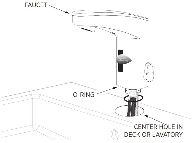
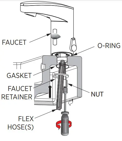
SLIDE GASKET OVER FLEX HOSE(S) AND SECURE
INSTALL STRAINER AND FLEX HOSE ONTO SUPPLY STOP. OPEN SUPPLY STOPS.
IMPORTANT: Flush dirt, debris, and sediment from supply line(s) before connecting flex hose(s).
A.Install strainer and flex hose(s) onto supply stop.
B.Tighten the flex hose(s) (with strainer in place) securely to the supply stop(s).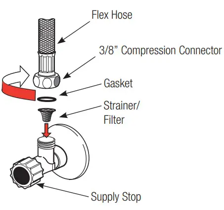 C.Open supply stop(s).
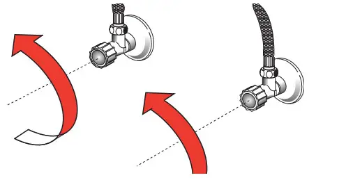
Note:
If water flows immediately after turning water stop to open position, then proceed to step 4 (leave the water running; there is a ‘water off’ signal when the faucet is first activated).
REMOVE LABEL FROM SENSOR
A.Remove Label from Sensor Window.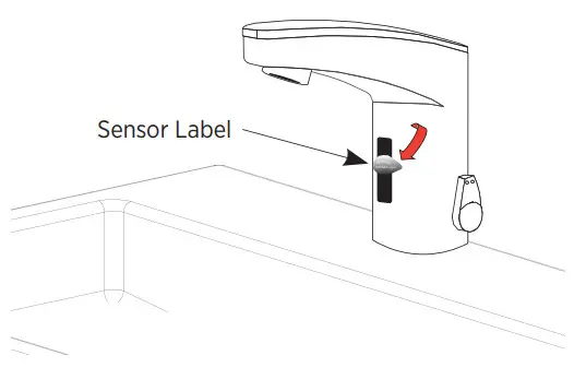
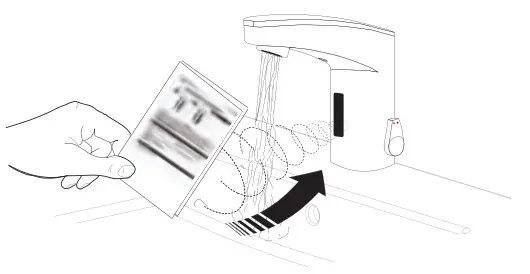
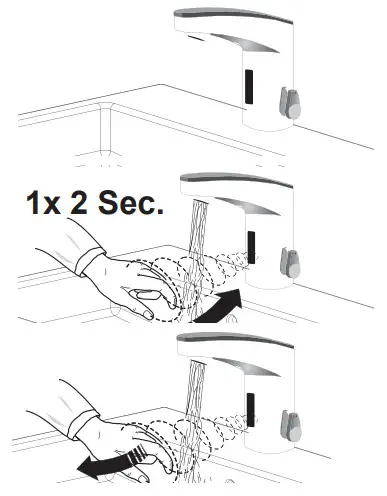
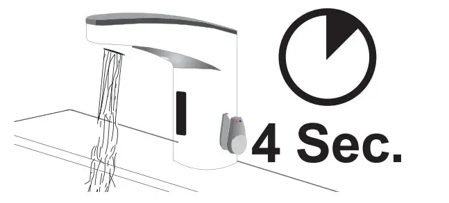
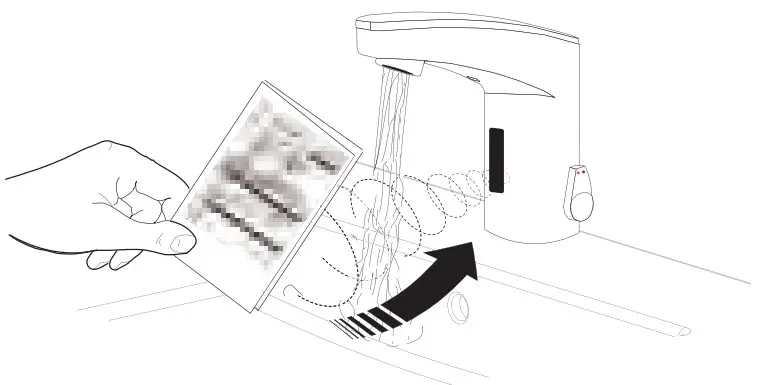
ACTIVATE FAUCET
A.Activate Faucet by holding installation instructions approximately 1-1/2” (38 mm) in front of the sensor window until the red light appears, then
remove the instruction sheet. The faucet will run for four (4) seconds and the range will automatically adjust to its environment. Wait ten (10) seconds
after water shuts off before using the faucet.
B.Activate Faucet and check for leaks. If the faucet does not function, refer to the Troubleshooting section of this instruction manual.
SET AND FIX TEMPERATURE
A.Adjust lever to set temperature.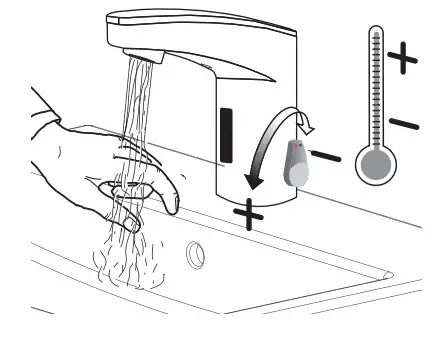 B.Optional – To fi x temperature, set lever to the desired position, then remove lever and plug hole with cap.
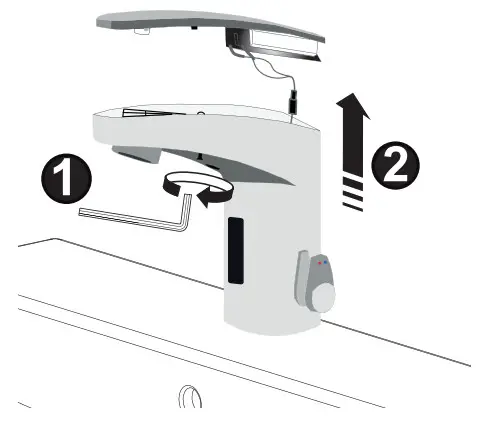
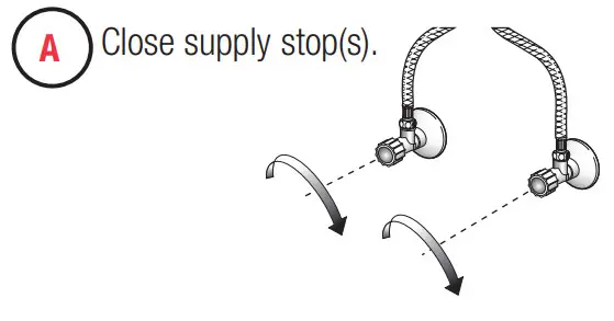
BATTERY REPLACEMENT
Note: Replace the battery when RED LED indicator flashes each time faucet is in use or when the faucet stops functioning.
A.Close supply stop(s).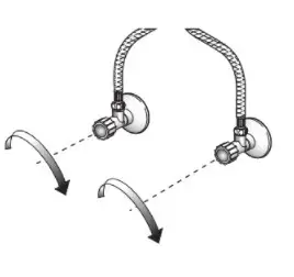
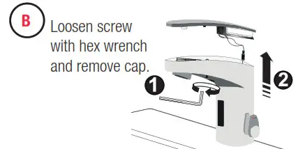
B.Loosen screws with hex wrench and remove the cap.
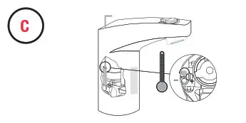
 C.Move battery retainer tab away from the battery. Remove the old battery. Dispose of properly Wait 15 seconds before installing the new battery.
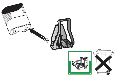
D.Insert a new 6V type CR-P2 lithium battery. The RED LED will flash for one (1) minute. Reinstall the battery cover. If LED doesn’t flash or if it just lights up, removes and then reinserts the battery. If water flows continuously after inserting the new battery and opening the supply stops, wait for 15 seconds, remove and then reinsert the battery.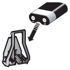
E.Replace the cover and tighten the screw with a hex wrench.

F.Open supply stop(s).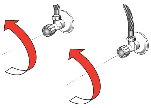 G.Wait ten (10) seconds before using the faucet.
SETTINGS
IR-Click Feature
The IR-Click is a detector located in the sensor window of the faucet spout that allows the user to place the faucet into the following function modes: continuous Run, Temporary Off, and Auto Set Range Adjustment. To use the IR-Click, cover the bottom half of the sensor with a finger wait 2 seconds for Green ight, then remove finger. When in programming mode, each touch of IR-Click will produce a quick Green flash.
| Function | Press Button | LED Signal |
| Temporary OFF (2 min) | 1.1 time for 2 seconds 2. 2 times (double push) | 1.LED Green (1) 2.LED Red pulsating flashes |
| reset: | 1 time or will reset automatically after 2 mins | |
| Continuous Run 2 min default setup (adjustable from 1-20 min) | 1.1 time for 2 seconds 2. 1 time for 3-5 seconds | 1.LED Green (1) 2.Water flows after releasing |
| reset: | 1 time or will reset automatically after 2 mins | |
| Auto Set Range Adjustment Details Shown in Next Section | 1.1 time for 2 seconds 2.2 times (double touch) 3.1 time for 4 seconds then hold till the requested range is reached 4.Release | 1.LED Green (1) 2.LED Red blinks 3.LED Red (1-8) 4.LED Green (1) |
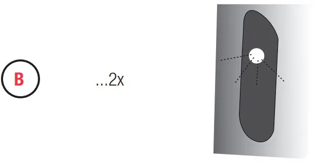
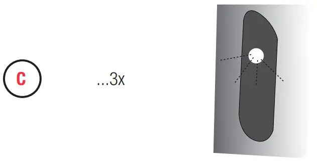
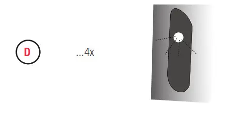
SENSOR RANGE ADJUSTMENT
FACTORY SETTING IS APPROPRIATE FOR THE MAJORITY OF APPLICATIONS AND SHOULD NOT REQUIRE RESETTING UNLESS UNDER EXTREME SITUATIONS.
A.IR activation (see page 5). To enter programming mode place finger on IR-Click (covering the bottom half of sensor) 1 time for 2 seconds and remove, REEN light will come on. Then, place finger 2 times then remove. The light on the sensor should blink RED to indicate programming mode.
 B.Cover IR-Click (bottom half of the sensor) until LED flashes RED 4 times – hold IR-Click until LED flashes 1 to 8 times from minimum to maximum range. See diagram below. Release when the requested range is reached.
C.

D.Wait until LED flashes GREEN

SENSOR RANGE ADJUSTMENT DIAGRAM
.![]()
12/24 LINE PURGE FEATURE
This feature will operate the faucet every 12 or 24 hours since last use, or if not used, to prevent stagnant water conditions.
The default purge duration is two minutes.
Consult factory regarding other timing options.
Steps to activate purge line feature:
- Activate IR: cover the lower part of the sensor window with a white card/paper until LED flashes GREEN to confirm program mode is active.
- Cover the lower part of the sensor window once more with a white card/paper for approximately 24 seconds (ignore LED indications during this period). Release when the requested program is reached. (See LED indications to right.)


Deactivate
Activate 12HR
Activate 24HR
Activate 48HR
HOT LIMIT STOP ADJUSTMENT

Activate 48HR


OPERATION
As the user’s hands enter the beam’s effective range, the beam is reflected back into the sensor receiver and activates the solenoid valve allowing water 10 Sec. to flow from the faucet. Water will flow until the hands are removed or until the faucet reaches its automatic time-out setting.
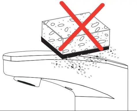
CARE AND CLEANING
DO NOT USE abrasive or chemical cleaners (including chlorine bleach) to clean faucets that may dull the luster and attack the chrome or special decorative finishes. Use ONLY mild soap and water, then wipe dry with a clean cloth or towel. While cleaning the bathroom tile, protect the faucet from any splattering of cleaner. Acids and cleaning fl uids will discolor or remove chrome plating.
TROUBLESHOOTING GUIDE
1. Problem: Faucet does not function.
Cause: Adhesive packaging label affixed over sensor eye.
Solution: Remove the adhesive label from the sensor eye.
Cause: Permanent Off Activated showed by RED flashing LED.
Solution: Touch button on sensor window for 2 seconds, RED flashing
LED will stop and confi rmed with GREEN LED.
2. Problem: Faucet delivers water in an uncontrolled manner.
Cause: The faucet is defective.
Solution Contact Sloan Technical Support (see below).
3. Problem: Faucet does not deliver any water with hands in sensor range.
Indicator: Solenoid valve produces an audible “click.”
Cause: Water supply stop(s) closed.
Solution: Open water supply stop(s).
Cause: Water supply stop strainer(s) clogged.
Solution: Turn off water at supply stop(s). Remove, clean, and reinstall water supply stop strainer(s). Replace strainer(s), if required.
Turn on the water at supply stop(s).
Indicator: Solenoid valve does not produce an audible “click.”
Cause: Battery low.
Solution: Replace the battery (refer to battery replacement).
Solution Contact Sloan Technical Support (see below)
4. Problem: After removing label water does not flow.
Use this installation guide as a target by placing it in front of the sensor (approx. 1-1/2” away) until water begins fl owing, then remove installation instruction from the sensor.
Water will stop fl owing, wait 10 seconds before using faucet.
5. Problem: Faucet delivers only a slow flow or dribble when the sensor is activated.
Cause: Water supply stop(s) are partially closed.
Solution: Completely open water supply stop(s).
Cause: Water supply stop strainer(s) clogged.
Solution: Turn off water at supply stop(s). Remove, clean, and reinstall water supply stop strainer(s). Replace strainer(s), if required.
Turn on the water at supply stop(s).
Cause: Spray head is clogged.
Solution Remove, clean, and reinstall spray head. Replace spray head, if required.
Cause: Faucet is defective.
Solution Contact Sloan Technical Support (see below).
6. Problem: Faucet does not stop delivering water or continues to drip after the user is no longer detected.
Cause: Faucet is defective.
Solution Contact Sloan Technical Support (see below).
7. Problem LED indicator blinks RED when the faucet is in use.
Cause: Battery low.
Solution: Replace battery (refer to battery replacement)
8. Problem: The water temperature is too hot or too cold on a faucet connected to hot and cold supply lines.
Cause: Supply stops are not adjusted properly.
Solution: Adjust supply stops.
Cause: For models with an integral mixing valve – The mixing valve is set improperly for the water temperature desired.
Solution: Rotate the mixing valve handle clockwise to decrease water temperature or counterclockwise to increase the water temperature.
When assistance is required, please contact Sloan Technical Support at: 1-888-SLOAN-14 (1-888-756-2614)
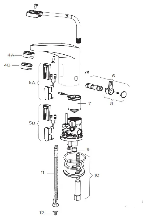
REPAIR PARTS LIST
| Item Part No. No. | Description | |
| 1 | EAF-60 | Cover |
| 2 | EAF-61 | Cover Clip — Battery Support |
| 3 | EFX-1015-A | Battery Replacement Kit (with 2.5 mm hex key) |
| 4A | EAF-22 | 1.5 gpm (5.6 Lpm) AER Spray Head |
| 4B | EAF-63 | 0.5 gpm (1.9 Lpm) AER Spray Head |
| 5A | EAF-1021-A | Electronic Sensor (15 Second Shut-off) with Fixing Clip Kit (0.5 gpm only) |
| 5B | EAF-1018-A | Electronic Sensor (7 Second Shut-off) with Fixing Clip Kit (1.5 gpm only) |
| 6 | EAF-1019-A | Mixer Handle Assembly and Cartridge Kit |
| 7 | EAF-2 | Solenoid Valve Cartridge (10 Faucet) |
| 8 | EAF-1020-A | Integral Side Mixer Handle Kit |
| 9 | EAF-8 | Back Check (2 required for ISM models) |
| 10 | EAF-1 | Faucet Mounting Kit |
| 11 | EAF-1008 | 13″ (330 mm) Flexible Supply Hose (2 required for ISM models) |
| 12 | EAF-9 | Filter (2 required for ISM models) |
1-888-SLOAN-14 (1-888-756-2614)
Sloan
10500 Seymour Avenue
Franklin Park, IL 60131
P: 847-671-4300 / 800-9-VALVE-9
F: 847-671-4380 / 800-447-8329
[email protected]
www.sloanvalve.com
© 2015 SLOAN VALVE COMPANY


