MBJ SAL-0910 Arealight Series LED Light User Manual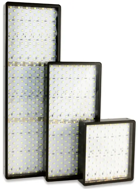
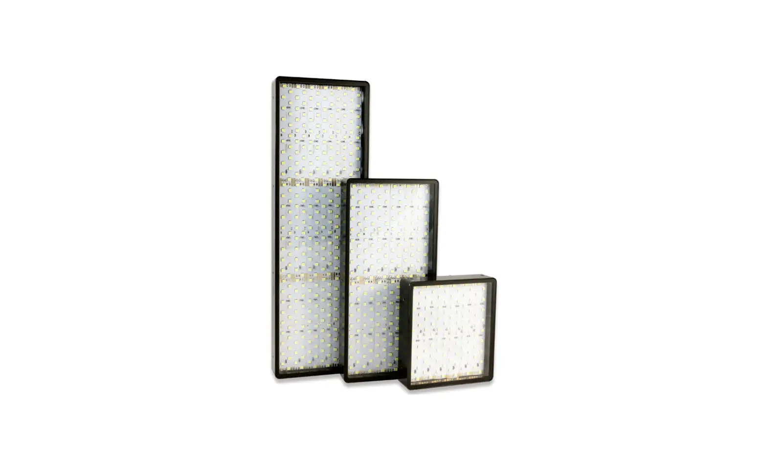
Model Sizes in Series
| The illumination is available in the following sizes 1) | ||
| SAL-0910 | SAL-0920 | SAL-0930 |
Possible LED Colors
| LED | Abbr.1) | Peak Wavelength2) |
| White | -WT | 5000K, min. CRI80 |
| Red | -RD | near 625 nm |
| Infrared | -IR | near 850 nm |
| Green | -GN | near 525 nm |
| Blue | -BE | near 465 nm |
| Yellow | -YE | near 580 nm |
- Color option will be added to the model name after the size information.
SAL-0920-RD referrs to a arealight with 625 nm red light. - This is an approximated value. The exact value also depends on LED temperature and LED current.
Safety Notes
Before working with this unit, read the warning and application instructions carefully and completely before operating the device.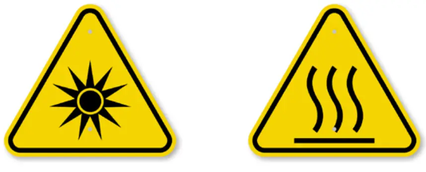
- The device is designed for indoor use only.
- Light – Due to the risk of flash burn of the eyes it is not recommended to look directly into the light source. The lighting must be switched off before installation and/or maintenance. The device must not be used when a failure may cause a personal injury.
- Heat – In case of insufficient heat dissipation or when running the light in flash mode with a too high duty cycle, the surface temperature may exceed 60 °C. Keep off flammable materials at any time.
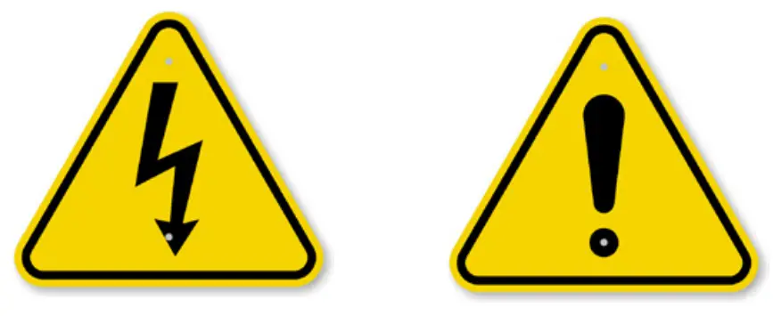
- Electricity – The housing is electrically isolated from the ground of the power supply. Exceeding the permissible input voltage Uin or ULED(+) can lead to the destruction of the device or to a significant shortening of the lifetime of the LEDs in the device.
- Usage – Please prevent mechanical stress to the light surface during operation. This will lead to an inhomogeneous light emission.
- Cleaning – The light emission surface has to be cleaned with a standard glass cleaner and a soft cleaning cloth. Do not use other materiel for cleaning as it will damage the device.
Manual Arealight Series: 23. May 2022
MBJ Imaging GmbH
Jochim-Klindt-Straße 7
+49 4102 778 90 31
22926 Ahrensburg, Germany
[email protected]
www.mbj-imaging.com
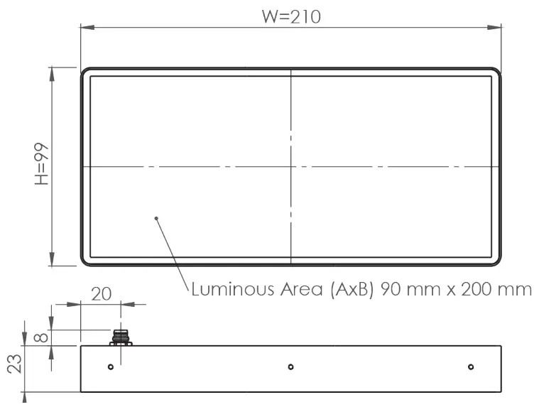
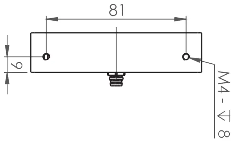
Mechanical Integration
The light is equipped with several combined mounting positions of M4 threaded holes. It can be used to fix the lighting to the specified position. In addition M2.5 threaded holes are provided at the two long sides to mount the foil and filter holder set. To secure a long live time additional heat transfer measurements at the holding postions is highly recommended.
Manual Arealight Series: 23. May 2022
Example: Model SAL-0920
More 2D and 3D drawings can be found online: www.mbj-imaging.com
| Specification | SAL-0910 | SAL-0920 | SAL-0930 |
| Operating temperature | 10°C to 30°C | ||
| Certifications | CE, RoHS | ||
| Degree of protection | IP54 | ||
| Humidity | 30 % to 70 % | ||
Electrical Connection
The lighting is equipped with an 4 pin M8x1 connector.
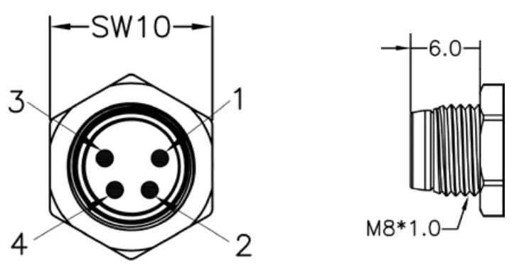
| Pin | Color 1) | Standard (-s) | Direct (-x) 2) |
| 1 | brown | 24 VDC | LED (+) |
| 2 | white | Dim | LED (+) |
| 3 | blue | Trigger | LED (-) |
| 4 | black | Ground | LED (-) |
- Wire color of MBJ lighting cable.
- Connection to 24VDC without external LED controller may destroy the unit.
Additional Information
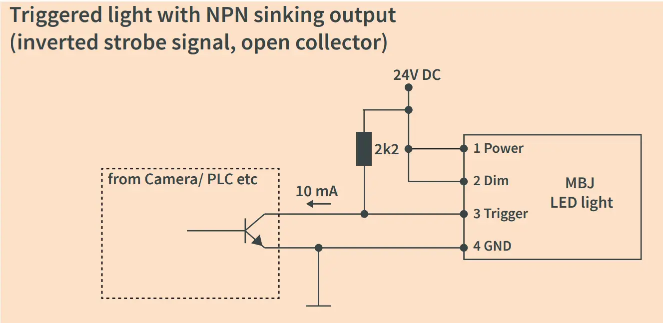
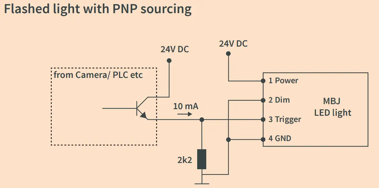
Pin 3 (Trigger) is an ‘active high’ input signal with 5…24V=ON and 0…1V=OFF, it is a high resistance current sink with 0.2mA for 5V and 5mA for 24V Pin 2 (DIM) is used as brightness control and operation mode switch, it is a high resistance current sink with 0.2mA for 5V and 1mA for 24V. For the connection it is recommended to use the MBJ lighting cable with a maximum length of 10m.
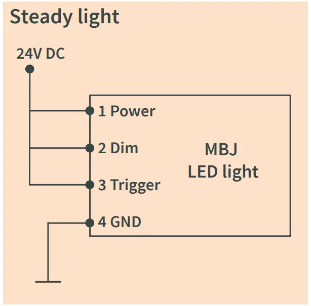
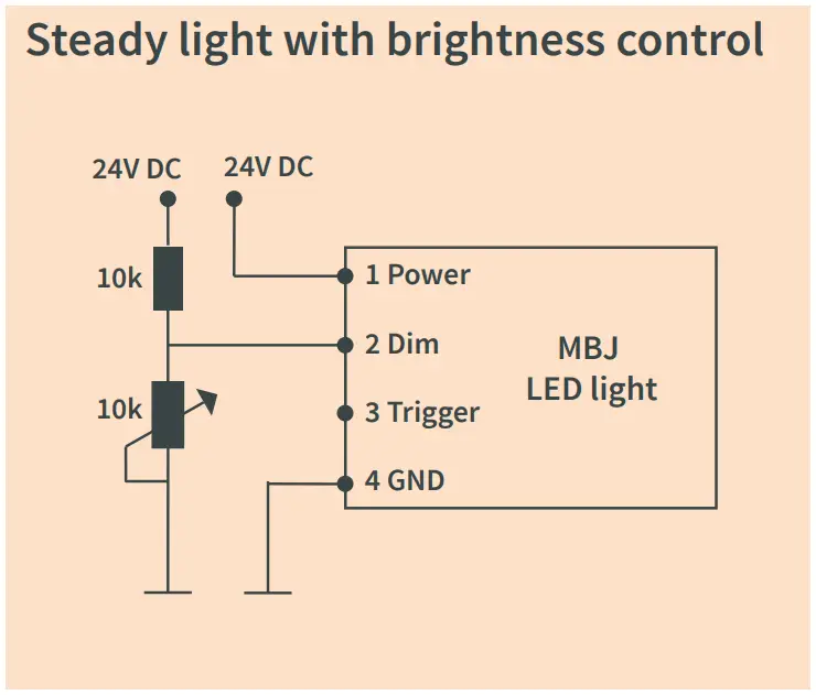
Integrated Controller (-s)
Supported operation modes with the integrated LED controller
| Pin 2 (Dim) | Operation mode |
| 24V | steady light 1) |
| 1…10V | steady light with brightness control 2) |
| 24V | triggered light |
| GND | triggered flash light with max. 20 ms and up-to 100 % more light intensity 3) |
- Pin 3 (Trigger) needs permanent 24V to activate steady light mode.
- PWM with 3.8 kHz clock is used, recommended minimal camera exposure is 5ms.
- Latency between trigger and LED light ON is about 20…30µs, the maximum recommended clock speed is 1 kHz, the maximum recommended duty cycle is 25% and the minimum recommended flash time is 100µs.
Specifications
| Specification | SAL-0910 | SAL-0920 | SAL-0930 |
| Optical parameter | |||
| Luminous area (A x B) or (ID^/OD) | 90 mm x 100 mm | 90 mm x 200 mm | 90 mm x 300 mm |
| Light emission | Areal, rectangular light field with direct light emission | ||
| Recommended use | Commonly used for brightfield applications, large objects or need for bright areal illumination, e.g. print inspection. Different lighting angles highlight varied surface characteristics. | ||
| Recommended light working distance | 10 mm – 400 mm | 10 mm – 550 mm | 10 mm – 700 mm |
| Luminous Flux of white LEDs 1) | 2760 lm | 5520 lm | 8280 lm |
| Radiant Power of red LEDs 1) | 8120 mW | 16240 mW | 24360 mW |
| Radiant Power of IR LEDs 1) | 3910 mW | 7820 mW | 11730 mW |
| Electrical parameter | |||
| Available interfaces | -s with integrated LED Controller and 4 operation modes; -x with direct LED access (external LED control is required) | ||
| Uin for -s Version | 24V DC +/- 5 % | ||
| ULed(+) range for -x version 2) | WT / BE / YE: 17 … 20 VDC; GN: 20 … 23 VDC; RD: 12 … 15 VDC; IR: 9 … 12 VDC | ||
| Typical Power (-s version) | |||
| Steady light operation (white / red / IR)3) | 17 W / 13 W / 14 W | 34 W / 26 W / 42 W | 51 W / 39 W / 42 W |
| During ON time at flashed light operation 4) | 46 W | 92 W | 112 W |
| Recommended LED current (-x version) | |||
| Steady light (100% duty cycle) | 900 mA (1350 mA for IR) | 1800 mA (2700 mA for IR) | 2700 mA (4050 mA for IR) |
| Flash light (50 % duty cycle, 500 ms pulse) | 1800 mA (1350 mA for IR) | 3600 mA (2700 mA for IR) | 5400 mA (4050 mA for IR) |
| Flash light (25 % duty cycle, 50 ms pulse) | 2700 mA (1350 mA for IR) | 5400 mA (2700mA for IR) | 8100 mA (4050 mA for IR) |
| Flash light (10 % duty cycle, 5 ms pulse) | 3600 mA (2700 mA for IR) | 7200 mA (5400 mA for IR) | 10800 mA (8100 mA for IR) |
| General parameter | |||
| Dimension (H x W x D) | 99 mm x 110 mm x 23 mm | 99 mm x 210 mm x 23 mm | 99 mm x 310 mm x 23 mm |
| Weight | 370 g | 760 g | 1155 g |
| Material | Anodized aluminum housing with PMMA light cover | ||
| Connector | M8x1 socket, 4 pin, male (for pinning details refer to chart “Electrical Connection”) | ||
| Accessories | For cable, foil holder brackets, light manipulation foils and external LED controller: please check www.mbj-imaging.com | ||
- Values are approximate with a +/- 7% tolerance
- Lower voltage value refers to steady light, higher voltage value refers to flash light, please see max. allowed current in the row below.
- Power for Blue / Yellow is comparable to White, Power for Green is approx. 1,2 times higher 4) Triggered flash light with max. 20ms and up to 100% more light intensity, calculated for White.
Application Samples for (-s) controller