![]() IPS Inverter Series
IPS Inverter Series
IPS1202, IPS2202
User Guide
Version 1.00
Package Contents
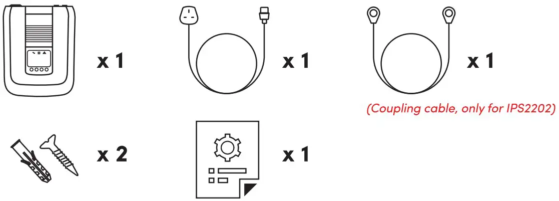
Note:
- The illustrations in this document may appear different from your model.
- If any of above item is not packed in your package when open, please consult your reseller immediately.
Overview
IPS1202/1PS2202
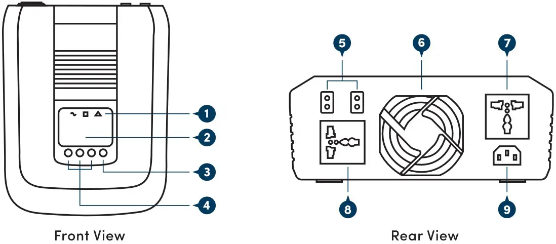
Legend:
- LED Indicator
- LCD
- Power On/Off switch
- Settings function buttons
- External battery connectors
- Cooling fan
- AC output receptacles 1
- AC output receptacles 2
- AC inlet
Installation
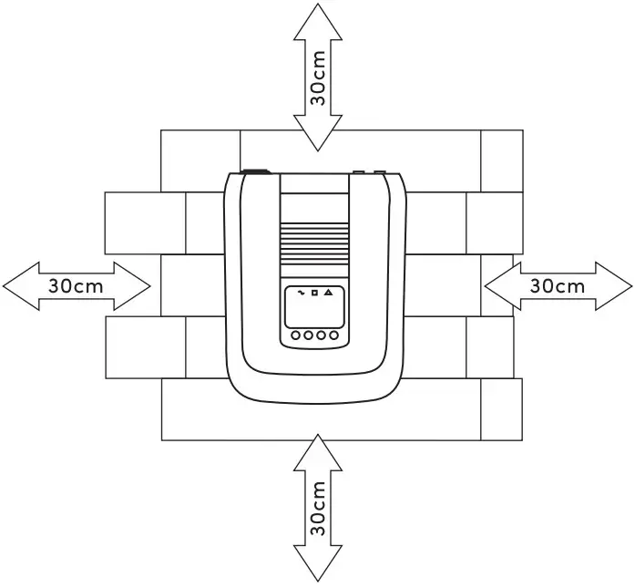
Safety Clearance
The minimum clearance to the wall shall be larger than 30cm in order to ensure proper ventilation. In the event the ambient temperature is high, it’s recommended to increase the distance of safety clearance to improve the heat dissipation.
Mounting Inverter on the wall
The inverter is designed to either be placed on horizontal surface or be mounted on the wall (as shown below). When mounting the inverter on the wall:
- The wall shall be solid and strong enough to carry the inverter;
- The location of installation shall allow the user to read the LCD easily;
- Two screws shall be firstly fixed on the wall (distance a s shown below) so that the inverter can be hung on the screws, recommended screw size is M4*50~65mm.
- After mounting the inverter, make sure it’s firmly mounted and won’t easily fall off in the event of unexpected earthquake or vibration.
Batteries
Determine the size of battery
The inverter is designed with pre-set charging current and voltage. Given a fixed charging current, under-sized batteries may shorten the battery life while over-sized batteries may result in unreasonable recharging time. It is recommended that the batteries capacity shall be no less than 100AH.
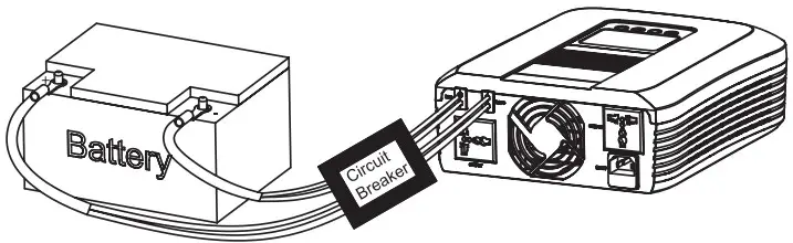
Connect the battery cables
- The gauge of battery cables shall be no less than 6 AWG with 105°C rating.
- No matter how the batteries are connected (in series or in parallel), make sure the cables terminal voltage is consistent with the inverter’s specification (12VDC for 1200VA model and 24VDC for 2200VA model).
- It is recommended to cover the battery terminals during the connection.
- Check the polarity of the cables before connecting to the inverter.
- Connect the Inverter DC cables with battery terminals as shown below.
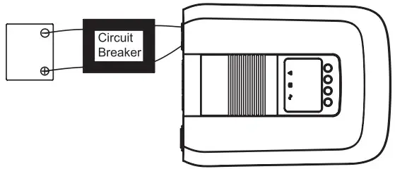
Connect with single battery
Make sure the battery voltage meets the inverter’s specification (only for 12VDC model).
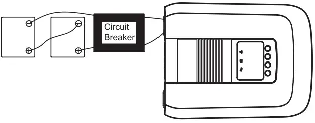
Connect with multiple batteries![]() While connecting multiple batteries, use the same brand/type for all batteries. Do not mix the battery bank with different brand/type of batteries.
While connecting multiple batteries, use the same brand/type for all batteries. Do not mix the battery bank with different brand/type of batteries.
The user may connect the batteries in series in order to double the voltage connected to inverter. The diagram below illustrates how to connect two 12VDC batteries in series to make up 24VDC (only for 24VDC model).
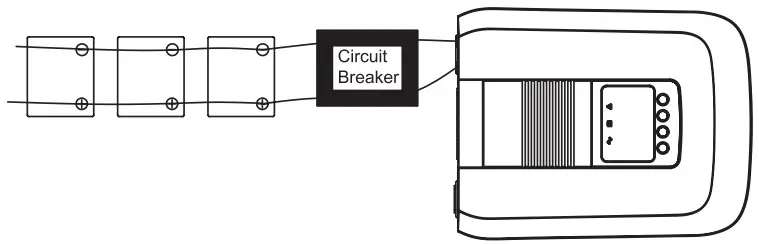
The user may connect the batteries in parallel in order to increase the total battery capacity without changing the battery voltage. The example below shows parallel connection of multiple 12VDC batteries. While the total capacity is times by the number of battery, the terminal voltage remains 12VDC (only for 12VDC model).
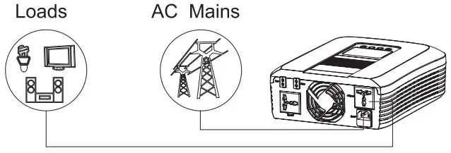
Connect AC input Cables and Loads
Connect the AC input cables and loads to the receptacles as shown below. Plug in the AC input power cord to the wall outlet. The unit will automatically charge the connected external battery even though the unit is off.
AC input voltage range selector
“NARROW’ setting:
Configure LCD to “NARROW” when connected to loads that are more sensitive on voltage range. With this setting, the inverter is more sensitive to the voltage disturbance on the AC input and input voltage range is set at 170~280VAC while output voltage follows input voltage.
“WIDE” setting:
Configure LCD to “WIDE” when connected to loads that are less sensitive on voltage range (e. g . light bulb, fan, fluorescent tube, or TV ) . With this setting, the input voltage range is set at 90~280VAC while output voltage follows input voltage.![]() Please note that the inverter’s transfer time switching from Line Mode to Backup Mode gets longer as the input voltage gets low. Under the circumstance, connecting the inverter with loads which are sensitive to transfer time (e.g. computer) might result in power interruption.
Please note that the inverter’s transfer time switching from Line Mode to Backup Mode gets longer as the input voltage gets low. Under the circumstance, connecting the inverter with loads which are sensitive to transfer time (e.g. computer) might result in power interruption.
Operations
After connecting batteries, AC input cables, and loads, the inverter is now ready for use.
Power On/Off
Once the inverter has been properly installed, press the power switch to turn on the unit. The unit will work automatically in line mode or inverter mode according to input utility power’s status. To turn the unit off, press the power switch again.
LED Indicators
The operation mode of the inverter can be easily understood by LED indicators. Please refer to the table below for details.
| LED Indicator | Information | ||
| Green | Line mode 1 (charge current >3A) | Green flashing every 2 seconds | |
| Line mode 1 (charge current 3A) | Green solid lighting | ||
| Off charge mode | Green flashing in order of: 0.5s On->0.5s Off->0.5s On->3.5s Off | ||
| Yellow | Battery mode | Yellow solid lighting | |
| Red | Overload | Red flashing every 0.5 seconds | |
| Fault | Red solid lighting | ||
Function Keys
| Function Keys | Description |
| To power On/Off | |
| To enter the setting mode or exit setting mode | |
| To go to the next selection page | |
| To confirm the selection in setting mode |
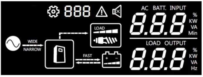
LCD Display
LCD displays the power flow and input/output readings inavisualized graphic design which allows the user to understand the operation status easily. The backlight of LCD remains on whenever the inverter is working (including Standby Charging Mode and Fault Mode).
| Icon | Function |
| Input source information | |
| Indicates the AC input | |
| Indicates input voltage | |
| Indicates the unit works in wide AC mode | |
| Indicates the unit works in narrow AC mode | |
| Configuration Program and Fault Information | |
| Indicates the setting programs | |
| Indicates the warning and fault codes | |
| Output information | |
| Indicates output voltage, load i n Watt | |
| Battery Information | |
| Indicates battery level by 0 – 2 4 % , 25-49%, 50-74% and 75-100% in battery mode and charging status | |
| Load Information | |
| Indicates the load level by 0-24%, 25-49%, 50-74% and 75-100% | |
| Mode operation information | |
| Indicates the unit connects to the mains | |
| Charging Information | |
| Indicates the AC charger current is setting to Maximum | |
LCD Setting
1) Display menu
The LCD display content will be changed in turns by pressing![]() button. The selectable information i s switched as below order:
button. The selectable information i s switched as below order:
AC input voltage, output voltage, battery voltage, output frequency, load percentage, load watt value. LCD will return to default LCD display after 30 seconds. Press![]() button to return to default LCD display immediately.
button to return to default LCD display immediately.
LCD Display Specification
| Page Number | Upper Area Digital Display | Lower Area Digital Display |
| 0 | AC 1/P Volt | 0/P Volt |
| 1 | NA | 0/P Volt |
| 2 | Battery Volt | 0/P Volt |
| 3 | Battery Volt | 0/P Freq |
| 4 | Battery Volt | Load 0/P Percent |
| 5 | Battery Volt | Load 0/P Watt |
| Operating mode | LCD Default Display |
| Standby Charging Mode | Utility input bypass to output, and battery can be charged without switching on the unit. The |
| Line Mode | Utility input bypass to output, and battery can be charged when switching on the unit |
| Backup Mode | The backup power to load comes only from battery |
2) Setting menu
After pressing and hold![]() button for 3 seconds, the unit will enter setting mode.
button for 3 seconds, the unit will enter setting mode.
Press![]() button to select setting programs, and then, Press
button to select setting programs, and then, Press![]() button to confirm the selection. To exit the setting mode, press and hold the
button to confirm the selection. To exit the setting mode, press and hold the![]() button for 3 seconds. Setting mode will exit if no button is pressed within 30 seconds.
button for 3 seconds. Setting mode will exit if no button is pressed within 30 seconds.
| Setting Items | Icons | Description |
| AC input voltage range | Acceptable AC input voltage will be within 90-280VAC (default) | |
| Acceptable AC input voltage will be within 170-280VAC | ||
| Maximum AC charging current | 1200VA model | |
| Default utility charging current is 20A. Selectable options of 0/10/15/25A is available | ||
| 2200VA model | ||
| Default utility charging current is 15A. Selectable options of 0/5/10/20A is available | ||
| Auto restart when overload occurs | Auto restart is off in battery mode (default) | |
| Auto restart is on in battery mode. Note: Inverter will reset twice every 30 sec before entering into fault mode if overload is not released | ||
| Setting Items | Icons | Description |
| Battery shutdown voltage setting | Setting range is from 10.0VDC to 11.0VDC for 12VDC model and 20.0VDC to 22.0VDC for 24VDC model. Low cut-off voltage will be fixed to setting value no matter what percentage of load is connected. Available options in 12VDC model : 10.0VDC (default)/10.2VDC/10.4VDC/10.6VDC/ 10.8VDC/11.0VDC. Available options in 24VDC model : 20.0VDC (default)/20.4VDC/20.8VDC/21.2VDC/ 21.6VDC/22.0VDC. | |
| Battery type | AGM (default) | AC CHG (bulk/floating): 14.2VDC/14.2VDC (12VDC model default) 28.4VDC/28.4VDC (24VDC model default) |
| User defined | After this option is selected, items 06 & 07 will take effect | |
| Bulk charging (C.V voltage) voltage | 12VDC Mode1:14.2VDC (default) 24VDC Mode1:28.4VDC (default) If self-defined is selected in program 05, this program can be set up. Setting range is from 13.0VDC to 14.6VDC for 12VDC model and increment of each click is 0.1VDC. Setting range is from 26.0VDC to 29.2VDC for 24VDC model and increment of each click is 0.2VDC. | |
| Floating charging voltage | 12VDC Mode1:13.7VDC (default) 24VDC Mode1:27.4VDC (default) If self-defined is selected in program 05, this prograrr can be set up. Setting range is from 13.0VDC to 14.6VDC for 12VDC model and increment of each click is 0.1VDC Setting range is from 26.0VDC to 29.2VDC for 24VDC model and increment of each click is 0.2VDC. | |
| Recover manufactory setting | Recover disable (default) | Enable/Disable (default) |
Battery Charging Status 1.2 KVA
| Status | Battery voltage | ||||
| 1 | 2 | 3 | 4 | ||
| Floating | Bat=13.7VDC | Solid on | Solid on | Solid on | Solid on |
| CV | 14.2>=Bat>=13.65VDC | Solid on | Solid on | Solid on | Flashing |
| CC | Bat>13.5VDC | Solid on | Solid on | Flashing | Flashing |
| 13.5>=Bat>13.0VDC | Solid on | Flashing | Flashing | Flashing | |
| Bat<=13.0VDC | Flashing | Flashing | Flashing | Flashing | |
Battery Charging Status 2.2 KVA
| Status | Battery voltage | ||||
| 1 | 2 | 3 | 4 | ||
| Floating | Bat=27.4VDC | Solid on | Solid on | Solid on | Solid on |
| CV | 28.4>=Bat>=27.3VDC | Solid on | Solid on | Solid on | Flashing |
| CC | Bat>27VDC | Solid on | Solid on | Flashing | Flashing |
| 27>=Bat>26VDC | Solid on | Flashing | Flashing | Flashing | |
| Bat<=26VDC | Flashing | Flashing | Flashing | Flashing | |
Fault and warning code
| Fault event or warning | Icon | Alarm |
| Battery low | Buzzing every 2 seconds | |
| Overload warning | Buzzing every 0.5 seconds | |
| High temperature | Buzzing every 0.5 seconds | |
| Output volt high | Buzzing continuously | |
| Output short | Buzzing continuously | |
| Over charge | Buzzing continuously | |
| Overload fault | Buzzing continuously | |
| Fan fail | Buzzing continuously | |
| Over temperature | Buzzing continuously |
Troubleshooting
| Problem | Possible Cause | Remedial Action |
| No LCD display | Battery voltage is low | Recharge the battery and check if the battery cables are well connected |
| Battery is defective | Replace the batteries | |
| Power button is not pressed | Press and hold the power button | |
| Mains are normal but works in backup mode | AC input is absent | Check the connection of AC input |
| Backup time is short | Overloading | Disconnect non critical loads |
| Battery voltage is too low | Recharge battery for at least 8 hours | |
| Battery is bad | Replace good quality batteries | |
| Alarm buzzer beeps continuously | Inverter entered into fault mode | Refer to the fault code to identify the fault and report to service representative for further assistances |
Specification
| Model | IPS1202 | IPS2202 | |
| Capacity | VA/W | 1200VA / 1000 W | 2200 VA / 1800 W |
| Nominal Battery Voltage | 12VDC | 24VDC | |
| Line Mode | |||
| Input | Nominal Voltage | 220-240VAC | |
| Voltage Range | Wide mode: 90VAC-280VAC (default) Narrow model: 170VAC-280VAC | ||
| Normal Frequency | 40-70 Hz (auto sensing) | ||
| Output | Voltage | Follow the Utility | |
| Frequency | Follow the Utility | ||
| Output Waveform | Follow the Utility | ||
| Efficiency | >95% (full R load, battery full charged) | ||
| Transfer Time | 15ms Typical, 40ms Max. | ||
| Battery Mode | |||
| Output | Voltage | 230VAC (+10%/ – 18%) | |
| Frequency | 50/60 Hz (auto detection) | ||
| Output Waveform | Modified sine-wave | ||
| Efficiency | >80% | ||
| Overload Protection | 1 min@ >110%, 20 s®> 120%, Os®>150% | ||
| Protection | Discharge, over charged, over loading, short circuit, over temperature protection | ||
| Battery Charger (Powered by AC) | |||
| Charging Algorithm | 3 stage charging | ||
| AC Charge Current | 20A (default), 0/10/15/25A (selectable) | 15A (default), 0/5/10/20A (selectable) | |
| Floating Charging Voltage | 13.7VDC | 27.4VDC | |
| Over Charging Voltage | 16VDC | 32VDC | |
| Physical | |||
| Total # of Inverter Receptacles | (2) UN | ||
| Dimension (W*H*D) | 309.5*96*244 mm | ||
| Weight | 2.5kg | 2.6kg | |
| Warning Diagnostics | |||
| Indicators | Inverter Status Display | ||
| Audible Alarms | Low battery, Overload, Fault | ||
| Environmental | |||
| Operating Temperature | 0°C to 55°C | ||
| Operating Relative Humidity | 5 to 95% Non condensing | ||
| Management | |||
| Auto-charger | Yes | ||
| Auto-restart | Yes | ||
Worldwide Customer Care Centers
| INDONESIA Office PT PROLINK INTIDATA NUSANTARA Walk-In: JI. Cideng Barat No. 79, Jakarta Pusat 10150, Indonesia. Telephone: +62 213483 1777 Sale Enquiries: [email protected] Technical Support: [email protected] | MALAYSIA Office FIDA SYSTEMS (M) SDN BHD Walk-In: 29 Jalan US] 1/31, 47600 Subang Jaya, Selangor Darul Ehsan, Malaysia. Telephone: +60 3 8024 9 1 5 1 Sale Enquiries: [email protected] Technical Support: [email protected] |
| SINGAPORE Office FIDA INTERNATIONAL (S) PTE LTD Walk-In: Block 1 6 Kallang Place #06-02, Kallang Basin Industrial Estate, Singapore 339156. Telephone: +65 6357 0668 Sale Enquiries: [email protected] Technical Support: [email protected] | Technical Support Hotline INDONESIA 2 +62 213483 1 7 1 7 MALAYSIA: +60 3 6023 9151 SINGAPORE: +65 6357 0666 |
Note: Closed on Saturdays, Sundays and local/regional Public Holidays.
Register online for your Product Warranty at www.prolink2u.com
Prolink is a registered trademark of Fida International (S) Pte Ltd. Other brands and product names are trademarks or registered trademarks of their respective holders. Product images are purely for illustrative purposes and may defer from the actual product. Specifications are subjected to changes without prior notice. Copyright © 2023 Fida International (S) Pte Ltd.
Kepada Yth.
Customer Service
PT. PROLINK INTIDATA NUSANTARA
Jl. Cideng Barat No. 79
Jakarta Pusat 10150 – Indonesia
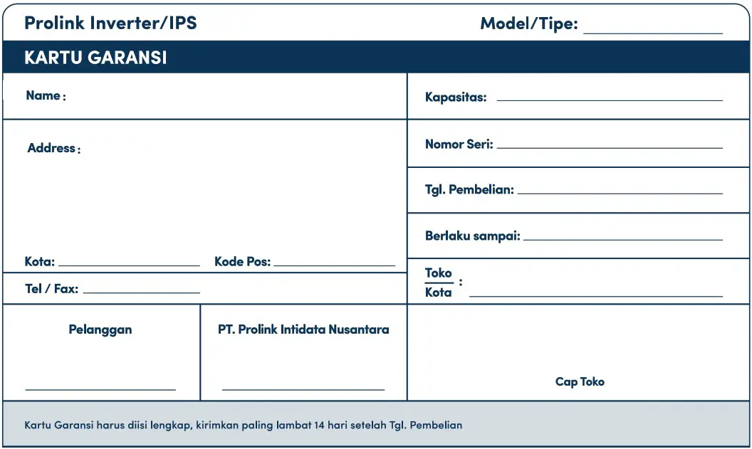
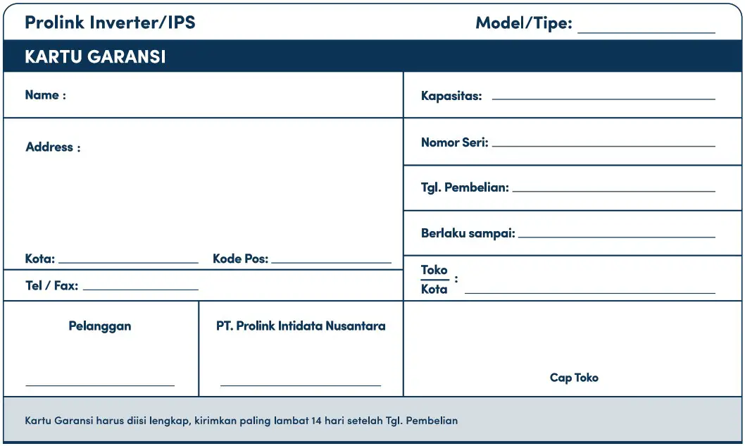
KARTU GARANSI
INDONESIA
![]() Alamat Pengiriman
Alamat Pengiriman
Address
PT. PROLINK INTIDATA NUSANTARA
JI. Cideng Barat No. 79 Jakarta Pusat 10150 – Indonesia
Telp. : (62-21) 34831777
Fax : (62-21) 34830788
Email : [email protected]


