![]()

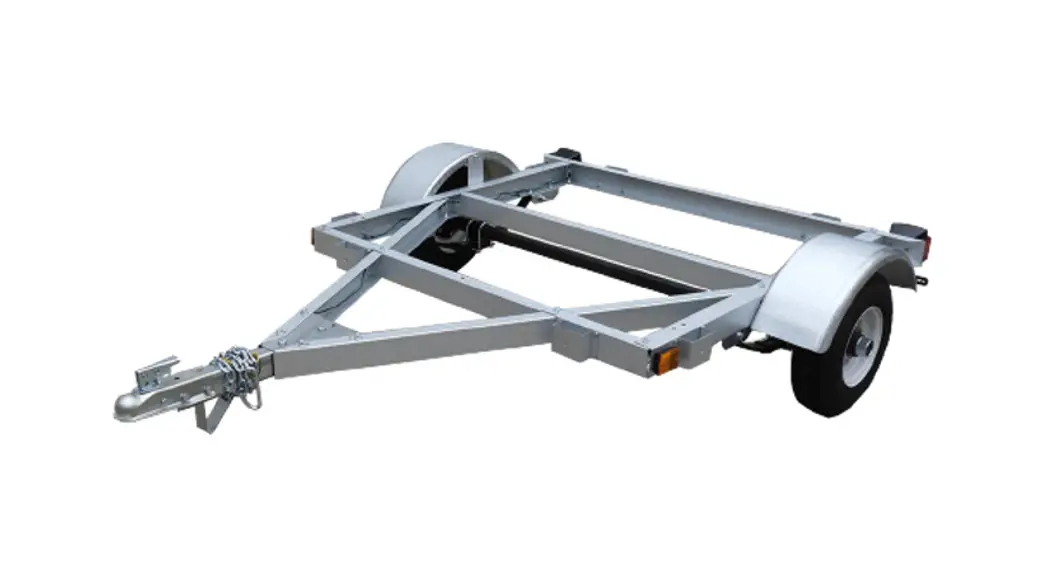
Kit Trailer Assembly Instructions
Model: 48-048-K08, 48-072-K08/K12
48-096-K08 & 60-096-K12
Carefully read and follow the assembly instructions in this manual.
Before using the trailer, carefully read the owner’s manual.
Save both manuals for future reference.
www.westbrooktrailers.com
Congratulations on the purchase of your kit trailer. Thank you for choosing Westbrook Trailers.
Safety Information
 It is important to read and understand all the instructions. Failure to follow all assembly instructions may result in serious injury.
- The edges of the trailer frame can be very sharp, it is IMPORTANT to ALWAYS wear the provided safety gloves when handling the material during unboxing and the assembly process.
- It is recommended that you use two people to assemble your trailer since you will need to turn the trailer during the assembly.
- Modification of the trailer structure can make the trailer unsafe and void your warranty. Any modifications made to the trailer must comply with DOT and NHTSA regulations and must not compromise the gross vehicle weight rating (GVWR) of the trailer.
Important Information
- Included in your kit is the completed New Vehicle Information Sheet (NVIS) or Certificate of Origin and the VIN label. These are important documents and are required to register your trailer. They are located on the outside of box #1in a brown envelope.
- If the NVIS form or Certificate of origin hasn’t been completed, please contact us at 866-8571445.
- Write the VIN of the trailer and the purchase date in the space below.
- Keep this manual and your receipt in a safe and dry place for future reference.
Serial Number : ______________________________ Purchase Date: _____________________
Unboxing your Trailer
The kit trailer is shipped in 3 boxes containing the following parts:
Make sure you have received all three boxes of the kit trailer. If any parts are missing or broken, please contact us at 866-857-1445 or email us at [email protected]. When contacting us about your trailer, please have the VIN of the trailer and the purchase order number available.
4’x4′ & 4’x6′ & 4’x8′
- Box # 1 – Includes tires, fenders, lights, small parts, and hardware. Remove the registration documentation affixed outside this box and keep it in a safe place until you are ready to get a license plate.
- Box # 2 – Includes the axle and all the frame channels.
- Box # 3 – Includes both axle springs.
5’x8′ - Box # 1 – Includes tires, fenders, lights, small parts, and hardware. Remove the registration documentation affixed outside this box and keep it in a safe place until you are ready to get a license plate.
- Box # 2 – Includes all the frame channels
- Box # 3 – Includes both axle and springs.
Part Listing
| BOX #1 TIRE & FENDER (ALSO INC3JUDES THE THREE BOXES BELOW) | 5′ x 8′ | ||||||||
| !TEMP ITEM DESCRIPTION | 4′ x 4′ 4′ x 6′ | ||||||||
| 500258 | “FENDER | 2 | 21 | ||||||
| 500841 | 80 X 8 UtC TIRE & WHEEL | 2 | 2 | ||||||
| 504212 | r FENDER | 2 | |||||||
| 500844 OX R 1 INTERIOR 500558 | .8x 12 MC TIRE ASSEMBLY BOX – LIGHTS WIRE CONNECTOR | ||||||||
| 500513 | TAIWGHT LEFT/DRIVER SIDE | 1 | 1 | 1 | 1 | ||||
| 500514 | TAIWGHT RIGHT/PASSENGER SIDE | 1 | 1 | 1 | 1 | ||||
| 500515 | AMBER MARKER LIGHT | 2 | 2 | 2 | 2 | ||||
| 500516 | PLASTIC LICENSE BRACKET | 1 | 1 | 1 | 1 | ||||
| 500512 | 4 WAY FLAT 20′ WIRE HARNESS | ||||||||
| BOX 4 1- INTERIOR 504447 | BOX – METAL ENDER PLATE – 8″/ 1r (504212) | ||||||||
| NGUE SUPPORT FOOT | 1 | 11 | 1 | ||||||
| AKE POCKET | 8 | 88 | 8 | ||||||
| 500259 | F SPRING MOUNTING BRACKET | 4 | 44 | 4 | |||||
| ”260 | F SPRING AXLE MOUNT PLATE | 2 | 22 | 2 | |||||
| 162 | ‘ TONGUE CONNECTION BRACKET | 1 | |||||||
| ONG COUPLER CHANNEL | |||||||||
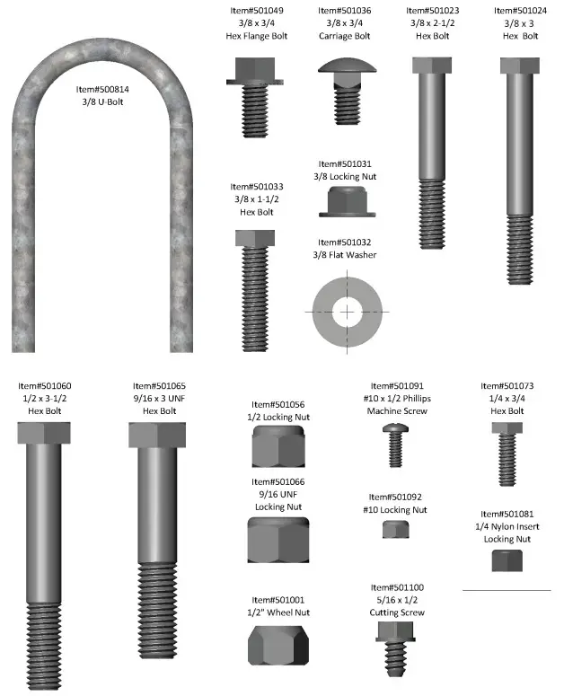
| BOX #1- INTERIOR BOX – HARDWARE (PICTURES ON THE RIGHT IN REAL SCALE FOR REFECENCE) | |||||||||
| •00814 3/8″ U BOLT | 4 | 4 – | |||||||
| •01049 | 3/8″ X 3/4″ HEX FLANGE BOLT | 20 | 1826 | 30 | |||||
| •01033 | 3/8″ X 1 1/2″ HEX BOLT | 10 | 1320 | 24 | |||||
| •11036 | 3/8″ X 3/4″ CARRIAGE BOLT | 8 | 88 | 8 | |||||
| •01031 | 3/8″ HE( FLANGE Lock nut | 46 | 4661 | 65 | |||||
| •11023 | /3/9- x 2-1/2′ HEX BOLT | 1 | 11 | 1 | |||||
| •01024 | 3/8″ X 3″ HEX BOLT | 2 | 22 | 2 | |||||
| •01032 | 3/8″ FLAT WASHER | 8 | 44 | 4 | |||||
| •01060 | 1/2″ X 3 1/2″ HEX BOLT | 2 | 22 | 2 | |||||
| •01056 | 1/2′ LOCKING NUT | 2 | 22 | 2 | |||||
| •01065 | 3/16 UNF X 3″ HEX BOLT | 4 | 44 | 4 | |||||
| •01066 | 9/16 UNF LOCKING NUT | 4 | 44 | 4 | |||||
| •01091 | #10 X 1/2″ PHIWPS #2 SCREW | 8 | 88 | 8 | |||||
| •11092 | #10 LOCKING NUT | 8 | 88 | 8 | |||||
| •11100 | 5/16 X lir CUTTING SCREW | 4 | 44 | 4 | |||||
| •01001 | 1/2″ WHEEL NUT | 10 | 1010 | 10 | |||||
| •01073 | 1/4 X 3/4″ HEX BOLT | 32 | 3232 | 32 | |||||
| •01081 | 1/4 NYLON INSERT LOCKING NUT | 32 | 3232 | 32 | |||||
| •00805 | 17/8″ COUPLER CLASS I | 1 | 11 | 1 | |||||
| •00804 | SAFETY CHAIN – 3/16 X 4′ (CLASS I) | 1 | 11 | 1 | |||||
| •03079 | r CABLE TIE | 4 | 64 | 4 | |||||
Part Listing
| OX 0.R. FR BOX | |||||
| ITEM# | ITEM DESCRIPTION | 4′ x 4′ | 4′ x 6′ | 4′ x 8′ | 5′ x 8′ |
| 500254 | FRONT CHANNEL | 1 | 1 | 1 | 1 |
| 500255 | CROSS CHANNEL | 1 | 2 | 4 | 5 |
| 500256 | REAR CHANNEL | 1 | 1 | 1 | 1 |
| 500251 | 4′ DRIVER SIDE CHANNEL (4X4) | 1 | |||
| 500297 | 4′ PASSENGER SIDE CHANNEL (4X4) | 1 | |||
| 500252 | 6′ DRIVER SIDE CHANEL (4X6) | 1 | |||
| 500298 | 6′ PASSENGER SIDE CHANNEL (4X6) | 1 | |||
| 500253 | 4′ FRONT DRIVER SIDE CHANNEL (4X8) | 1 | 1 | ||
| 500299 | 4′ REAR DRIVER SIDE CHANNEL (4X8) | 1 | 1 | ||
| 500300 | 4′ FRONT PASSENGER SIDE CHANNEL (4X8) | 1 | 1 | ||
| 500301 | 4′ REAR PASSENGER SIDE CHANNEL (4X8) | 1 | 1 | ||
| 500272 | CONNECTION CHANNEL (4X8) | 2 | 2 | ||
| 500257 | TONGUE CHANNEL | 2 | 2 | 2 | 2 |
| 504162 | 5′ – TONGUE CONNECTION BRACKET | 1 | 1 | 1 | 1 |
| 500047 | 4′ STRAIGHT AXLE | 1 | 1 | 1 | |
| 504238 | TONGUE CROSS CHANNEL | 1 | |||
| BOX # 3 SPRING (4’x4′ & 4’x6′ & 4’x8′) | ||||
| 500809 | 750 LB. SLIPPER SPRING | 2 | 2 | 2 |
| BOX # 3 AXLE & SPRING (5′ x 8′) | |||
| 500809 | 750 LB. SLIPPER SPRING | ||
| 504617 | 5′ STRAIGHT AXLE | 2 | 1 |
Assembly Instruction:
Before you begin, you need to prepare a large area to work. To facilitate the assembly process the instructions have been broken down in sections, before you begin the assembly of a each section gather all the parts listed and carefully read all the instructions. Half-way into the assembly process, you will need to flip the trailer and this will require two people.
- Ratchet with Socket : 10mm, 3/8”, 7/16” deep socket x 2, ½”, 9/16”, 13/16”, 7/8”,
- Wrench: 9/16”, ¾”, 7/8”
- Phillips Screwdriver
- Torque Wrench
- Knife
- Pliers
- Gloves (included)
- QE Code for assembly

https://www.youtube.com/watch?v=KvMjQjf8a5o&list=PLUEUarAVFwH3oS5tqfN-nitgKGzFlShDU&index=9
***Video show assembly of 4′ x 8′ kit trailers, which includes most of the step for all other sizes***
STEP 1– Stake Pocket Installation
| ITEM # | DESCRIPTION | QTY |
| 504471 | STAKE POCKET | 8 |
| 501073 | 1/4 X 3/4” HEX BOLT | 32 |
| 501081 | 1/4 LOCKING NUT | 32 |
- Line the stake pocket (504471) to the pre-drilled holes of the frame. There are eight locations.
- Secure with ¼ x 3/4 hex bolts (501073) and ¼ (501081) lock nut using 7/16 deep socket. Do this for all eight stake pockets.
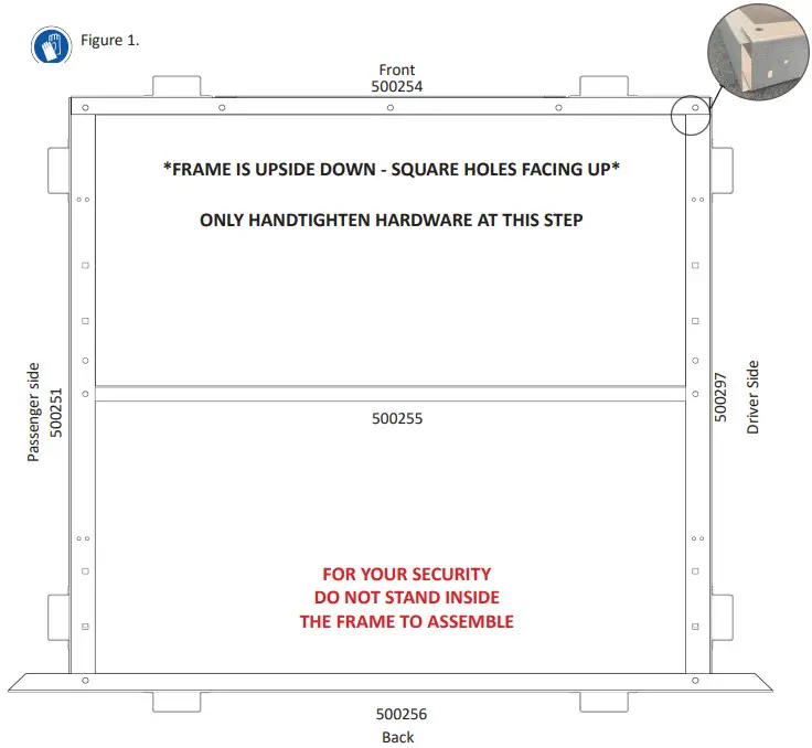
STEP 2a- Frame Assembly – 4’x 4’ Kit Trailer Frame
| ITEM # | PARTS DESCRIPTION | QTY |
| 501049 | 3/8 X 3/4” HEX FLANGE BOLT | 6 |
| 501033 | 3/8 X 1 1/2” HEX BOLT | 6 |
| 501031 | 3/8 Lock nut | 12 |
| 500254 | FRONT CHANNEL | 1 |
| 500255 | CROSS CHANNEL | 1 |
| 500256 | REAR CHANNEL | 1 |
| 500251 | 4’ DRIVER SIDE CHANNEL | 1 |
| 500297 | 4’ PASSENGER SIDE CHANNEL | 1 |
| TBD | Electrical Wire Grommet | 2 |
- You will be assembling the trailer upside down to avoid having to flip it twice during the assembling process.
- Gather the frame pieces and the hardware placing them in their respective position as shown in Figure 1.
- When placing your frame piece, match the hole configuration shown in figure 1. For example the passenger side channel the square holes should be facing up.
- Both passenger and driver side channel overlaps with the front channel; do not insert one inside the other.
(see Figure #1). Loosely connect the channel using the 3/8 x 3/4 hex flange bolt and 3/8 lock nut on the top, and the 3/8 x 1 1/2 hex bolt and 3/8 lock nut at the bottom. The 3/8 X 1 1/2” bolts will be used to secure the plywood floor with frame. - Take a cross-channel and install a grommet on each hole, then loosely connect it to the frame using the 3/8 x 3/4 flange bolt and 3/8 lock nut on top and the 3/8 x 1-1/2 hex bolt and 3/8 lock nut at the bottom.
- Repeat for other side.
- Slide the rear channel over the passenger and driver’s side channel and loosely connect using the 3/8 x 3/4 flange bolts and 3/8 lock nuts on top, and the 3/8 x 1-1/2 hex bolts and 3/8 lock nuts at the bottom.
4’x 4’ Kit Trailer Frame![]() The edges of the trailer can be very sharp. To prevent injury, wear the provided safety gloves
The edges of the trailer can be very sharp. To prevent injury, wear the provided safety gloves
Figure 1.
Step 1b- Frame Assembly – 4’x 6’ Kit Trailer Frame
| ITEM # | PARTS DESCRIPTION | QTY |
| 501049 | 3/8 X 3/4 HEX FLANGE BOLT | 4 |
| 501033 | 3/8 X 1 1/2 HEX BOLT (FULL THREAD) | 8 |
| 501031 | 3/8 FLANGE LOCK NUT | 12 |
| 500254 | FRONT CHANNEL | 1 |
| 500255 | CROSS CHANNEL | 1 |
| 500256 | REAR CHANNEL | 1 |
| 500252 | 6’ DRIVER SIDE CHANNEL | 1 |
| 500298 | 6’ PASSENGER SIDE CHANNEL | 1 |
IMPORTANT INFORMATION
- You will be assembling the trailer upside down to avoid having to flip it twice during the asembling process.
- Gather the frame pieces and the hardware placing them in their respective position as shown in Figure When placing your frame piece, match the hole configuration shown in figure 1. For example the passenger side channel the square holes should be facing up.
- The longer hex bolts will be used to secure the plywood floor with frame.
ASSEMBLY INSTRUCTION
- Both passenger and driver side channel overlaps with the front channel; do not insert one inside the other.
(see Figure #1). Loosely connect the channel using the 3/8 x 3/4 hex flange bolt and 3/8 lock nut on the top, and the 3/8 x 1 1/2 hex bolt and 3/8 lock nut at the bottom. - Take a cross-channel and install a grommet on each hole, then loosely connect both to the frame using the 3/8 x 1-1/2 hex bolt and 3/8 lock nut at the bottom only. The top will be secured when you install the axle.
- Repeat for other side.
- Slide the rear channel over the passenger and driver’s side channel and loosely connect using the 3/8 x 3/4 flange bolts and 3/8 lock nuts on top, and the 3/8 x 1-1/2 hex bolts and 3/8 lock nuts at the bottom.
Assemble the frame but only hand-tighten the hardware, they will be tightened in a later step.
4’x 6’ Kit Trailer Frame![]() The edges of the trailer can be very sharp. To prevent injury, wear the provided safety gloves
The edges of the trailer can be very sharp. To prevent injury, wear the provided safety gloves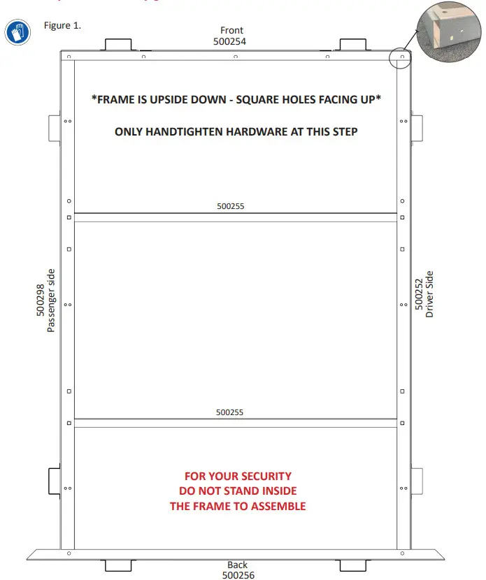
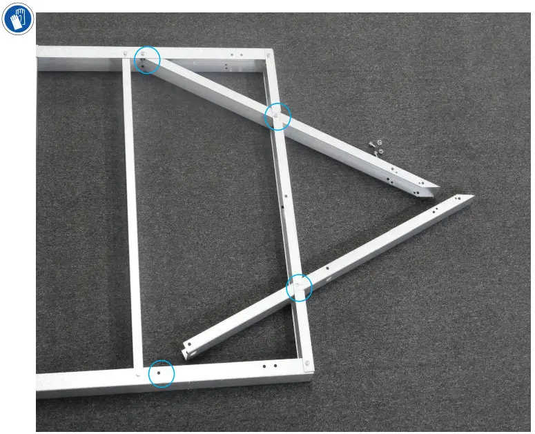
Step 1c- Frame Assembly – 4’x 8’ Kit Trailer Frame
| ITEM # | PARTS DESCRIPTION | QTY |
| 501049 | 3/8 X 3/4” HEX FLANGE BOLT | 12 |
| 501033 | 3/8 X 1 1/2” HEX BOLT (FULL THREAD) | 8 |
| 501031 | 3/8 NYLON INSERT HEX FLANGE Lock nut | 20 |
| 500254 | FRONT CHANNEL | 1 |
| 500255 | CROSS CHANNEL | 4 |
| 500256 | REAR CHANNEL | 1 |
| 500253 | 4’ FRONT DRIVER SIDE CHANNEL | 1 |
| 500299 | 4’ REAR DRIVER SIDE CHANNEL | 1 |
| 500300 | 4’ FRONT PASSENGER SIDE CHANNEL | 1 |
| 500301 | 4’ REAR PASSENGER SIDE CHANNEL | 1 |
| 500272 | CONNECTION CHANNEL | 2 |
IMPORTANT INFORMATION
- You will be assembling the trailer upside down to avoid having to flip it twice during the asembling process.
- Gather the frame pieces and the hardware placing them in their respective position as shown in Figure When placing your frame piece, match the hole configuration shown in figure 1. For example the passenger side channel the square holes should be facing up.
- The longer hex bolts will be used to secure the plywood floor with frame.
ASSEMBLY INSTRUCTION
- Both passenger and driver side channel overlaps with the front channel; do not insert one inside the other. (see Figure #1). Loosely connect the channel using the 3/8 x 3/4 hex flange bolt and 3/8 lock nut on the top, and the 3/8 x 1 1/2 hex bolt and 3/8 lock nut at the bottom. The 3/8 X 1 1/2” bolts will be used to secure the plywood floor with frame.
- Take the first cross-channel and install a grommet on each hole, then loosely connect it to the frame using the 3/8 x 3/4 flange bolt and 3/8 lock nut on top and the 3/8 x 1-1/2 hex bolt and 3/8 lock nut at the bottom.
- Slide the connection channel over top of the front and back side channels. Then add the second crosschannel to the first hole of the connection channel and fasten all three channels at the bottom only using the 3 /8 x 1-1/2 hex bolt 3 /8 lock nut. The top will be secured when you install the axle.
- Loosely connect the center of the connection channel using the 3 /8 x 3/4 flange bolts and 3/8 lock nut on top, and the 3 /8 x 1-1/2 hex bolt and 3 /8 lock nut at the bottom.
- Connect the third cross-channel to the last hole of the connection channel and fasten all three channel at the bottom using the 3 /8 x 1-1/2 hex bolt 3 /8 lock nut. The top will be secured when you install the axle.
- Repeat step 2 for the fourth cross-channel
- Repeat steps 1 – 6 for the other side. Repeat for other side.
- Slide the rear channel over the passenger and driver’s side channel and loosely connect using the 3/8 x 3/4 flange bolts and 3/8 lock nuts on top, and the 3/8 x 1-1/2 hex bolts and 3/8 lock nuts at the bottom.
Assemble the frame but only hand-tighten the hardware, they will be tightened in a later step.
4’x 8’ Kit Trailer Frame –
The edges of the trailer can be very sharp. To prevent injury, wear the provided safety gloves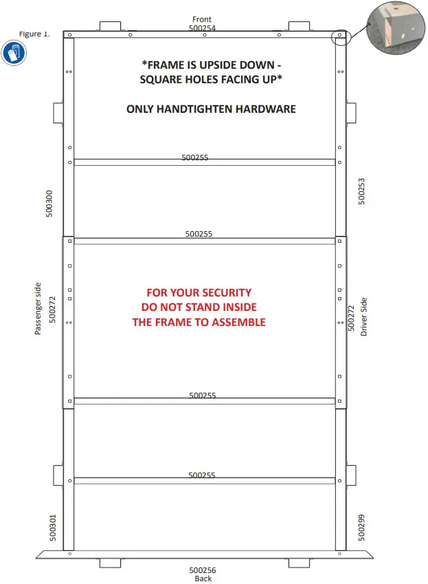
Step 1d- Frame Assembly – 5’x 8’ Kit Trailer Frame
| ITEM # | PARTS DESCRIPTION | QTY |
| 501049 | 3/8 X 3/4” HEX FLANGE BOLT | 14 |
| 501033 | 3/8 X 1 1/2” HEX BOLT (FULL THREAD) | 14 |
| 501031 | 3/8 NYLON INSERT HEX FLANGE Lock nut | 28 |
| 504599 | FRONT CHANNEL | 1 |
| 504602 | CROSS CHANNEL | 5 |
| 504600 | REAR CHANNEL | 1 |
| 500253 | 4’ FRONT DRIVER SIDE CHANNEL | 1 |
| 500299 | 4’ REAR DRIVER SIDE CHANNEL | 1 |
| 500300 | 4’ FRONT PASSENGER SIDE CHANNEL | 1 |
| 500301 | 4’ REAR PASSENGER SIDE CHANNEL | 1 |
| 500272 | CONNECTION CHANNEL | 2 |
IMPORTANT INFORMATION
- You will be assembling the trailer upside down to avoid having to flip it twice during the asembling process.
- Gather the frame pieces and the hardware placing them in their respective position as shown in Figure When placing your frame piece, match the hole configuration shown in figure 1. For example the passenger side channel the square holes should be facing up.
- The longer hex bolts will be used to secure the plywood floor with frame.
ASSEMBLY INSTRUCTION
- Both passenger and driver side channel overlaps with the front channel; do not insert one inside the other. (see Figure #1). Loosely connect the channel using the 3 /8 x 3/4 hex flange bolt and 3/8 lock nut on the top, and the 3/8 x 1 1/2 hex bolt and 3/8 lock nut at the bottom. The 3 /8 x 1 1/2” bolts will be used to secure the plywood floor with frame.
- Slide the connection channel over top of the front and back side channels.
- Insert the first cross-channel and align with the first hole of the connection channel. Loosely secure all three channels at the bottom only ith the 8 x 1-1/2 hex bolt 3/8 lock nut. When you put the axle in place, the op will be heldin place.
- Position the second cross-channel opening toward the front channel and the third one facing the opposite way. (figure 1). Loosely connect both cross-channels to all three channels and loosely fasten at the bottom using the 3 /8 x 1-1/2 hex bolt 3 /8 lock nut and at the top with 3 /8 x 3/4 hex flange bolt and 3/8 lock nut.
- Connect the fourth cross-channel to the last hole of the connection channel and fasten all three channel at the bottom using the 3 /8 x 1-1/2 hex bolt 3 /8 lock nut. The top will be secured when you install the axle.
- The 3/8 x 3/4 flange bolts and 3/8 lock nut on top and the 3 /8 x 1-1/2 hex bolt and 3/8 lock nut (on the bottom are used to attach the fifth connection channel.
- Repeat steps 1 – 5 for the other side.
- The 3/8 x 3/4 flange bolts and 3/8 lock nuts on top and the 3/8 x 1-1/2 hex bolts and 3/8 lock nuts on the bottom are used to connect the rear channel to the passenger and driver’s side channels.
5’x 8’ Kit Trailer Frame –
The edges of the trailer can be very sharp. To prevent injury, wear the provided safety gloves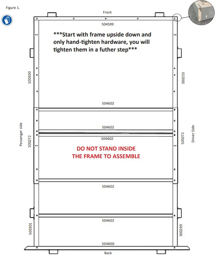
STEP 3 – Axle Assembly
| ITEM # | DESCRIPTION | QTY |
| 500047/ | 4’ STRAIGHT AXLE or 5′ STRAIGHT AXLE | 1 |
| 500809 | 750 LB. SPRINGS | 2 |
| 500814 | 3/8-16 U-BOLT | 4 |
| 500259 | LEAF SPRING MOUNTING BRACKET | 4 |
| 500260 | LEAF SPRING AXLE MOUNT PLATE | 2 |
| 501031 | 3/8-16 NYLON INSERT HEX FLANGE Lock nut | 16 |
| 501036 | 3/8 X 3/4” CARRIAGE BOLT | 8 |
| 501032 | 3/8” FLAT WASHER | 8 |
| 501065 | 9/16-18 UNF X 3” HEX BOLT | 4 |
| 501066 | 9/16-18 UNF NYLON INSERT LOCKING NUT | 4 |
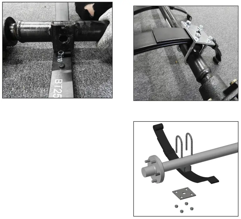
STEP 3 – Axle Assembly
- Secure the leaf spring mounting brackets in the square holes on each side of the trailer with the carriage bolt 3/8
x 3/4 and 3/8 lock nut using 9/16 socket; the round holes of the brackets should be oriented closest to the center. - Where there is no cross-channel at the fastening location of the mounting bracket use a 3/8 washer as a spacer.
- Lay the axle between the mounting brackets.
- Place the springs inside the mounting bracket with eye of the spring towards the front and the flat side towards the back of the trailer. Secure the spring to mounting bracket with the 9/16 hex bolts and 9/16 lock nuts using 7/8 socket and wrench. Do not over-tighten as there needs to be movement in the spring. Do this for both sides
- Place the first U-bolt around the axle. Line up the leaf spring mount plate with the oval holes running in the same direction as your leaf spring. Hand-tighten with the 3/8 locking nut. Repeat for all other U-bolts
- Secure all the U-bolts with a 9/16 socket.
- Using two people, flip the frame.
![]() CAUTION! FLIPPING THE TRAILER OVER REQUIRES TWO PEOPLE
CAUTION! FLIPPING THE TRAILER OVER REQUIRES TWO PEOPLE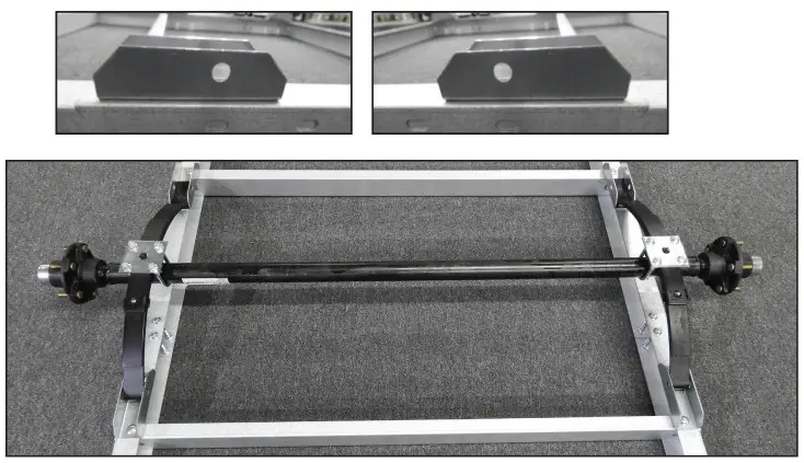
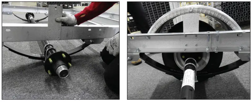
Step 4– Fender & Wheels
| ITEM # | DESCRIPTION | QTY |
| 501091 | #10 X 1/2″ PHILLIPS #2 MACHINE SCREW | 8 |
| 501092 | #10 LOCKING NUT | 8 |
| 501049 | 3/8 X 3/4″ HEX FLANGE BOLT | 6 |
| 501031 | 3/8 NYLON INSERT LOCKING NUT | 6 |
| 501001 | 1/2″ WHEEL NUTS | 10 |
| 48-048-K08, 48-072-K08, 48-096-K08 (8″ Wheel) | ||
| 500258 | 8″ FENDER | 2 |
| 500841 | 4.80 X 8 LRC TIRE & WHEEL | 2 |
| 504447 | FENDER PLATE – 8″ | 2 |
| 48-072-K12, 48-096-K12,60-096-K12 (12″ Wheel) | ||
| 504212 | 12″ FENDER | 2 |
| 500844 | 4.80 X 12 LRC TIRE & WHEEL | 2 |
| 504476 | FENDER PLATE – 12″ | 2 |
- Align the fender support plate with the frame and secure with the #10 machine screws and #10 lock nuts using a 3/8 socket and Phillips screwdriver. If the holes are not perfectly aligned use a punch to align them.
- Place the fender over top of the fender plate, hand-tighten the top hole using the 3/8 x ¾ Hex flange bolt and 3/8 lock nut, making sure the nut is inside of the fender.
- Place the tire on the hub and secure it to the rim with 1/2 wheel nuts using 13/16 socket and torque to 95ft-lbs.
- Hand tighten the other two holes to the frame using the 3/8 x ¾ Hex flange bolts and 3/8 lock nuts
- Tighten all the fender bolts using a 9/16 socket and wrench.
- Repeat for other side.
Step 5 – Tongue Assembly
| ITEM # | DESCRIPTION | 4 FT | 5 FT |
| 500257 | TONGUE CHANNEL | 2 | 2 |
| 504623 | TONGUE CROSS CHANNEL | 1 | |
| 504162 | 5’ – TONGUE CONNECTION BRACKET | 1 | 1 |
| 501049 | 3/8 X 3/4” HEX FLANGE BOLT | 8 | 10 |
| 501033 | 3/8 X 1 1/2” HEX BOLT (FULL THREAD) | 4 | 6 |
| 501031 | 3/8 NYLON INSERT HEX FLANGE Lock nut | 4 | 6 |
| 501100 | 5/16 UNC X 1/2” CUTTING SCREW WITH | 4 | 4 |
| 500512 | 4 WAY FLAT 20’ WIRE HARNESS | 1 | 1 |
- Take the two tongue channels and slide them through the vertical slots of the front channel and hand tighten to the frame in two places using the 3/8 x 1 1/2 hex bolts and 3/8 lock nuts on top and the flange bolts 3/8 x ¾ (and 3/8 lock nuts at the bottom . *FOR 5X8 TONGUE ASSEMBLY ONLY**
Put tongue cross channel in between tongue channel. Fastern it with the 3/8 x 1 1/2 hex bolts and 3/8 lock nuts on top and the flange bolts 3/8 x ¾ and 3/8 lock nuts at the bottom.
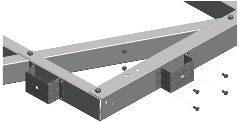
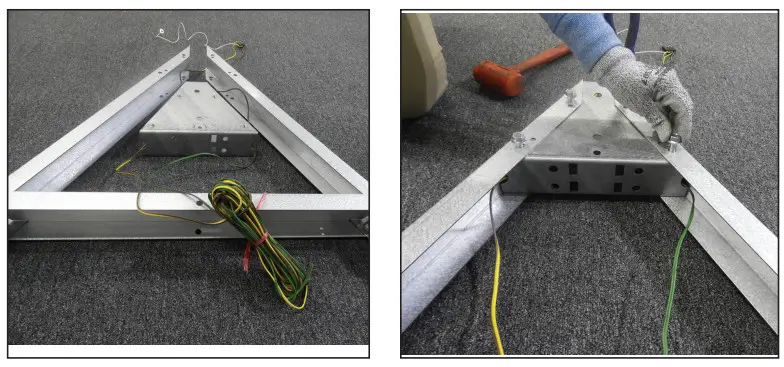
Step 6 – Tongue Connection Support Installation
- Put the tongue connection bracket with the threaded holes facing up place without sliding it fully into position
- Feed each wire of the wire harness between the tongue channel and separate your wire as follows.
• Yellow and brown on the driver’s side
• Green and brown wire on the passenger’s side
• Do not pull the white wire through, you will secure it to the coupler channel once it’s assembled. - Slide the tongue connection bracket (in place and hand tighten using the 3/8 x 3/4 flange bolts on top.
- On the bottom, in the four pre-drilled holes, secure with the cutting screws using a 1/2 socket.
- Secure the top bolts using 9/16 socket.
- Tighten all the bolts of the trailer frame using a 9/16 socket and wrench. If you are going to add a plywood sheet before using the trailer, you don’t need to tighten the top bolts until the plywood has been added.
Step 7 – Hitch and Safety Chains
| ITEM # | DESCRIPTION | QTY |
| 504163 | LONG COUPLER CHANNEL | 1 |
| 504198 | TONGUE SUPPORT FOOT – CHANNEL TONGUE | 1 |
| 500805 | 1 7/8” COUPLER CLASS I | 1 |
| 500804 | SAFETY CHAIN – 3/16 X 4’ (CLASS I) | 1 |
| 501031 | 3/8 NYLON INSERT LOCKING NUT | 3 |
| 501023 | 3/8 X 2-1/2” HEX BOLT | 1 |
| 501024 | 3/8 X 3” HEX BOLT | 2 |
| 501060 | 1/2 X 3 1/2” HEX BOLT | 2 |
| 501056 | 1/2 NYLON INSERT LOCKING NUT | 2 |
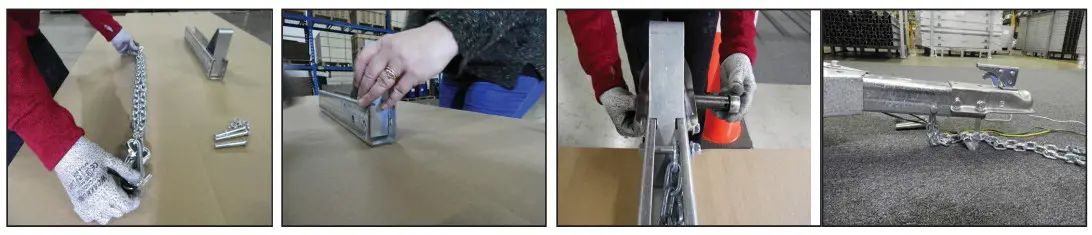
Assembled the coupler upside down.
- Place the long coupler channel with the opening facing up.
- Take the safety chain by the two hooks and find the center link. Place the bolt through the third hole of the channel and center link, and hand-tighten using the 2-1/2 hex bolt (and 3/8 lock nut .
- Insert the tongue support foot into the coupler channel as far as it will go.
- Put the coupler on the channel and secure with 3/8 x 3 hex bolts and 3/8 lock nuts using a 9/16 socket and wrench, making sure it’s tight enough that the tongue foot doesn’t move but the coupler spring releases.
- Pull the excess wire through the connection bracket leaving enough wire at the front to connect the white wire to the coupler.
- Slide the assembled coupler channel into the tongue connection being careful not to pinch the wiring.
- Line up the holes with the holes of tongue connection bracket and secure with 1/2 x 3 1/2 hex bolts (& ½ lock nuts tighten using 3/4 socket and wrench.
- Remove the 3/8 lock nut (from the chain bolt and place ring terminal of the ground (white wire) on the bolt and secure holding the 9/16 wrench on the nut and 9/16 socket on the bolt head. Do not over tighten as you may damage the ring terminal
 STEP 8 – Wiring & Lights
| ITEM # | DESCRIPTION | 4’ x 4’ | 4’ x 6’ | 4’ x 8’ | 5′ x 8′ |
| 500512 | 4 WAY FLAT 20’ WIRE HARNESS | 1 | 1 | 1 | 1 |
| 503079 | 8” CABLE TIE | 4 | 6 | 6 | 6 |
| 500558 | WIRE CONNECTOR | 2 | 2 | 2 | 2 |
| 500513 | TAILLIGHT LEFT/DRIVER SIDE | 1 | 1 | 1 | 1 |
| 500514 | TAILLIGHT RIGHT/PASSENGER SIDE | 1 | 1 | 1 | 1 |
| 500515 | AMBER MARKER LIGHT | 2 | 2 | 2 | 2 |
| 500516 | PLASTIC LICENSE BRACKET | 1 | 1 | 1 | 1 |
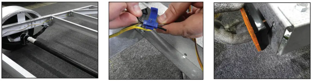
- Feed the wire harness using the pre-cut holes all the way to the back and tuck some of the wire in the front corner for the marker light.
- Place the amber marker light in the pre-drilled holes and secure it to the frame.
- With a knife carefully separate the brown and coloured wire near the front corner and marker light.
- Push the brown wire from the wire harness completely to the back of the wire connector.
- Slide the marker light wire into the blue connector without exposing any wire.
- Squeeze the metal blade of the connector down with pliers tight enough to make a connection between both wires. Verify that the blade is all the way in place and close the cover.
- At the back of the trailer, cut the wire leaving 6”, then strip 1/4” and twist the copper wire. Do this for both sides.
- Plug each wire to the corresponding hole in the back of each taillight, and secure them to the frame.
- Secure the license plate holder on the driver’s side with the taillight.
- Pull the excess wire back into the frame and secure it with the zip ties using the holes.
- Always test the lights before using the trailer.
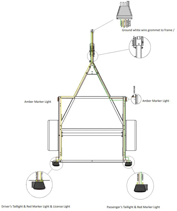
Wiring Diagram
- Ground=White Wire
- Tail/Running Lights/Marker Lights = Brown
- Left Turn/Brake = Yellow
- Right Turn/Brake = Green
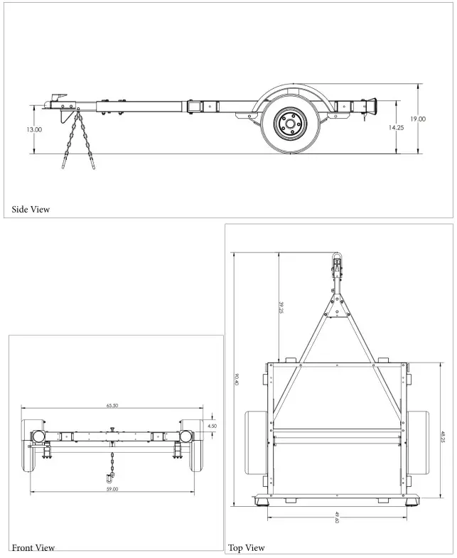
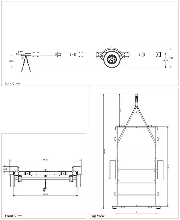
48-048-K08-Measurements
4ft x 4ft Plywood Drill Template
(Plywood not included)
Drill 3/8 holes in plywood using the dimensions outlined below and use the 3/8 x 1-1/2 full thread hex bolts to secure to the frame.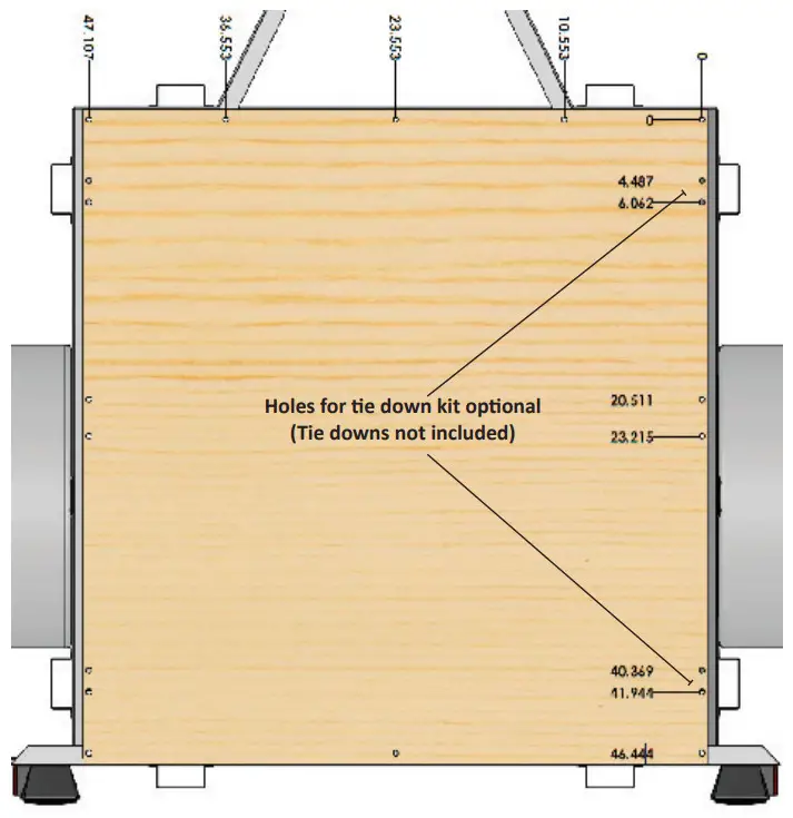
4ft x 6ft Plywood Drill Template
(Plywood not included)
Drill 3/8 holes in plywood using the dimensions outlined below and use the 3/8 x 1-1/2 full thread hex bolts to secure to the frame.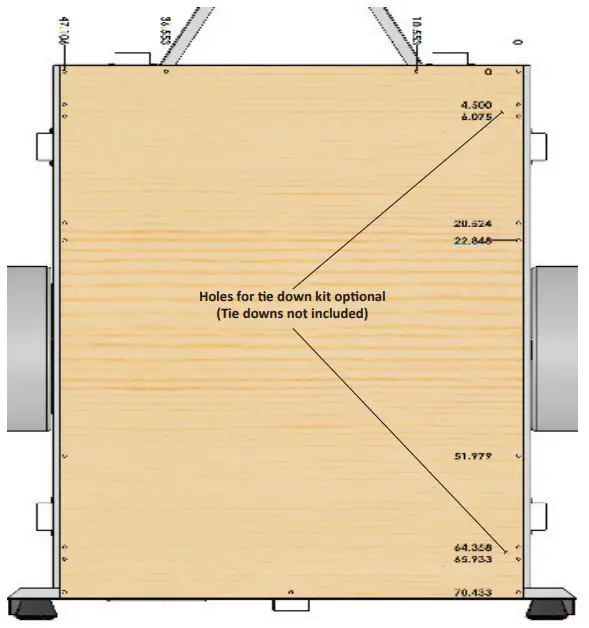
4ft x 8ft Plywood Drill Template
(Plywood not included )
Drill 3/8 holes in plywood using the dimensions outlined below and use the 3/8 x 1-1/2 full thread hex bolts to secure to the frame.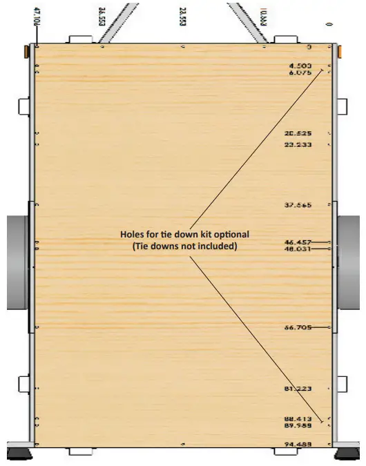
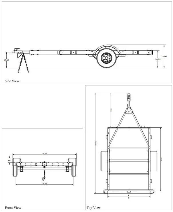
60-096-K12-Measurements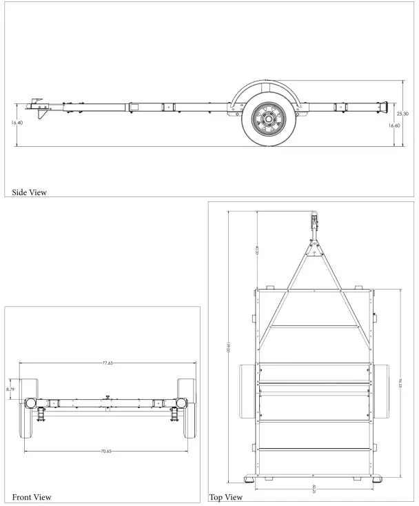
4ft x 8ft Plywood Drill Template
(Plywood not included )
Drill 3/8 holes in plywood using the dimensions outlined below and use the 3/8 x 1-1/2 full thread hex bolts to secure to the frame.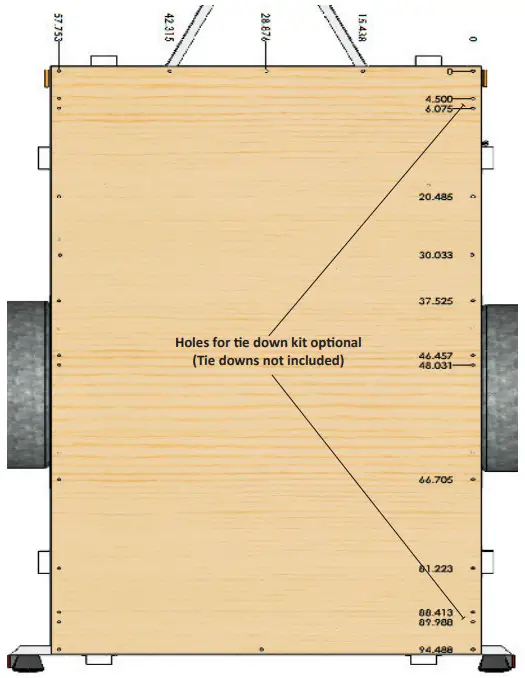
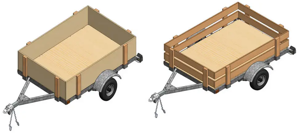
Cut List – Plywood
(Wood not included)
4’ x 4’
a. 8pcs – 2×4 –18” (12ft -2×4 makes 8pcs)
b. 4pcs – 3/4 x 14-3/4” x 48”
4’ x 6’
a. 8pcs – 2×4 –18” (12ft -2×4 makes 8pcs)
b. 2pcs – 3/4 x 14-3/4” x 72”
c. 2pcs – 3/4 x 14-1/4” x 48”
4’ x 8’
a. 8pcs – 2×4 –18” (12ft -2×4 makes 8pcs)
b. 2pcs – 3/4 x 14-3/4” x 96”
c. 2pcs – 3/4 x 14-1/4” x 48”
5’ x 8’
a. 8pcs – 2×4 –18” (12ft -2×4 makes 8pcs)
b. 2pcs – 3/4 x 14-3/4” x 96”
c. 2pcs – 3/4 x 14-1/4” x 60”
Cut List – Wood Plank
(Wood not included)
4’ x 4’
a. 8pcs – 2×4 -18” (12ft -2×4 makes 8pcs)
b. 8pcs – 1×6 – 48”
4’ x 6’
a. 8pcs – 2×4 – 18” (12ft -2×4 makes 8pcs)
b. 4pcs – 1×6 – 72”
c. 4pcs – 1×6 – 48”
4’ x 8’
a. 8pcs – 2×4 – 18” (12ft -2×4 makes 8pcs)
b. 4pcs – 1×6 – 96”
c. 4pcs – 1×6 – 48”
5’ x 8’
a. 8pcs – 2×4 – 18” (12ft -2×4 makes 8pcs)
b. 4pcs – 1×6 – 96”
c. 4pcs – 1×6 – 60”
Assembly instructions for kit trailers P. 33
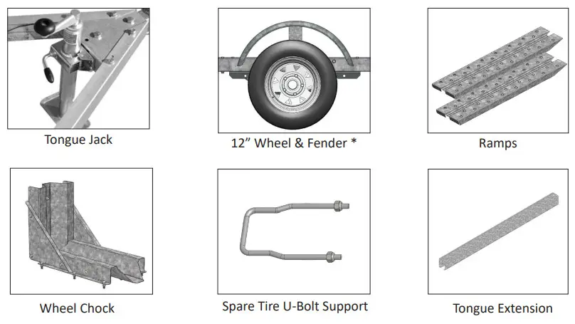
Trailer Accessories